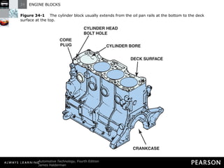
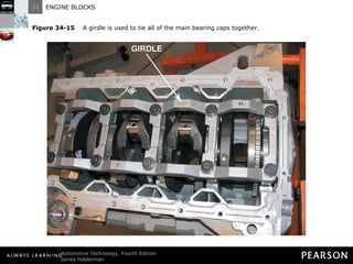
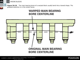
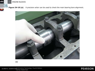
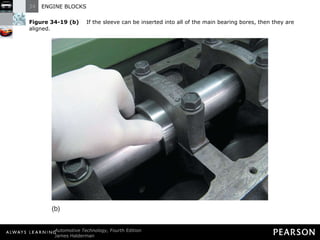
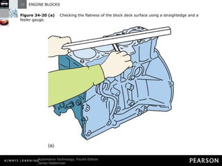
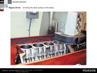
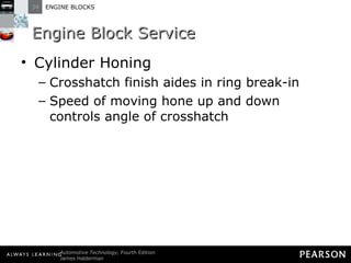
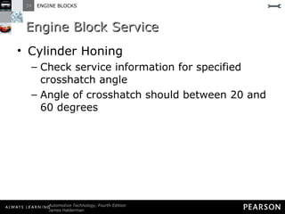
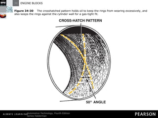
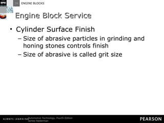
ENGINE BLOCKS 34
Objectives The student should be able to: Prepare for ASE Engine Repair (A1) certification test content area “C” (Engine Block Diagnosis and Repair).  Describe the types of engine blocks and how they are manufactured.  Measure cylinder bores.
Objectives The student should be able to: Discuss the machining operations required on most engine blocks.  List the steps necessary to prepare an engine block for assembly.
ENGINE BLOCKS
Engine Blocks Construction Supporting structure for engine Made of one of the following: Gray cast iron
Engine Blocks Construction Made of one of the following: Cast aluminum Die-cast aluminum alloy
Engine Blocks Construction Cast iron contains about 3% carbon (graphite) Steel is iron with carbon removed Carbon makes cast iron hard but brittle
Engine Blocks Construction Cast iron is used for engine blocks and cylinder heads for these reasons: Carbon allows for easy machining Graphite has lubricating properties
Engine Blocks Construction Cast iron is used for engine blocks and cylinder heads for these reasons: Cast iron is strong for its weight and usually magnetic Liquid cast iron poured in mold made of sand or Styrofoam
Engine Blocks Construction Other engine parts mounted on or in block Large casting supports crankshaft and camshaft Casting holds parts in alignment
Engine Blocks Construction Newer blocks use thin walls to reduce weight Block is often of monoblock design Cylinder, water jacket, main bearing supports, oil passages cast as one structure
Engine Blocks Construction Cylinder holes called bores and are made by boring ?
Figure 34-1   The cylinder block usually extends from the oil pan rails at the bottom to the deck surface at the top.
Engine Blocks Construction Combustion pressure loads carried from head to crankshaft through block Webs, walls, drilled passages contain coolant and lubricating oil
Engine Blocks Construction Mounting pads transfer engine torque to frame through engine mounts Bell housing of transmission attached to rear of block Joints between components sealed with gaskets or sealants
Engine Blocks Block Manufacturing Trend is to make blocks with larger cores, fewer pieces Before casting, cores are supported in core box
Engine Blocks Block Manufacturing Core box shapes outside of block Alloy cast iron is poured into box, flows between core and core box liner
Engine Blocks Block Manufacturing As cast iron cools, core breaks up Hardened cast iron removed from core box Openings in block are plugged with core plugs
Figure 34-2   An expansion (core) plug is used to block the opening in the cylinder head or block the holes where the core sand was removed after the part was cast.
Engine Blocks Block Manufacturing Block made with minimum thickness to reduce weight Cast iron for thin-wall casting contains higher nickel content and is harder
Engine Blocks Aluminum Blocks Nonmagnetic and lightweight Styrofoam often used for core
Engine Blocks Aluminum Blocks Styrofoam vaporizes on contact with molten aluminum leaving cavity where aluminum flows
Figure 34-3   A Styrofoam casting mold used to make the five cylinder engine blocks for the Chevrolet Colorado and the Hummer H3. The brown lines are glue used to hold the various parts together. Sand is packed around the mold and molten aluminum is poured into the sand which instantly vaporizes the Styrofoam. The aluminum then flows and fills the area of the mold.
Engine Blocks Aluminum Blocks Aluminum block engines usually require cast-iron cylinder walls Types of cylinder walls Cast-iron cylinder sleeves
Engine Blocks Aluminum Blocks Types of cylinder walls Sleeves are cast in aluminum block during manufacturing or pressed into block
Engine Blocks Aluminum Blocks Types of cylinder walls Sleeves not in contact with coolant passage are called dry cylinder sleeves
Figure 34-4   Cast-iron dry sleeves are used in aluminum blocks to provide a hard surface for the rings.
Engine Blocks Aluminum Blocks Types of cylinder walls Some block designs cast from silicon-aluminum with no cylinder liners
Engine Blocks Aluminum Blocks Types of cylinder walls Pistons with zinc-copper-hard iron coatings are used in the aluminum bores
Engine Blocks Aluminum Blocks Types of cylinder walls Some die-cast aluminum blocks have replaceable cast-iron cylinder sleeves
Engine Blocks Aluminum Blocks Types of cylinder walls Sleeves sealed at block deck and at their base
Engine Blocks Aluminum Blocks Types of cylinder walls Coolant flows around cylinder sleeve, so it’s called wet cylinder sleeve
Figure 34-5   A dry sleeve is supported by the surrounding cylinder block. A wet sleeve must be thicker to be able to withstand combustion pressures without total support from the block.
Engine Blocks Aluminum Blocks Cast-iron main bearing caps used for strength
Engine Blocks Bedplate Design Blocks Bedplate is structural member attached to bottom of block to support crankshaft Oil pan mounted under bedplate
Figure 34-6   A bedplate is a structural part of the engine which is attached between the block and the oil pan and supports the crankshaft.
Engine Blocks Casting Numbers Cast engine parts numbered to identify casting Numbers can be used to check dimensions, such as displacement
Figure 34-7   Casting numbers identify the block.
Engine Blocks Block Deck Cylinder head fastened to top surface of block The surface is called block deck
Engine Blocks Block Deck Block deck has smooth surface to seal against head gasket Bolt holes positioned around cylinders
Engine Blocks Block Deck Four, five, or six head bolts used for each cylinder Bolt holes fit into reinforced areas of block Additional holes in block transfer coolant and oil
Figure 34-8   The deck is the machined top surface of the block.
Engine Blocks Cooling Passages Coolant passages around cylinders called cooling jacket In most cylinder designs, cooling passages extend nearly to bottom of cylinder
Engine Blocks Cooling Passages In some cylinder designs, cooling passages are limited to upper portion ?
Engine Blocks Cooling Passages Siamese cylinder bores—cylinder walls cast together without water jacket between cylinders
Engine Blocks Cooling Passages Design improves strength and stability of bores Can reduce cooling
Figure 34-9   Cutaway of a Chevrolet V-8 block showing all of the internal passages.
Engine Blocks Lubricating Passages Oil holes drilled in block during manufacture Oil holes called oil gallery
Engine Blocks Lubricating Passages After oil holes drilled, unneeded open ends are capped  Caps are called oil gallery plugs End plugs can be source of oil leakage
Figure 34-10   Typical oil gallery plugs on the rear of a Chevrolet small block V-8 engine.
Figure 34-11   Small block Chevrolet block. Note the left-hand dipstick hole and a pad cast for a right-hand dipstick.
Engine Blocks Main Bearing Caps Main bearing caps cast or manufactured from sintered or billeted materials Machined and installed on block
Engine Blocks Main Bearing Caps Main bearing caps cast or manufactured from sintered or billeted materials Main bearing bores and cam bearing bores machined to correct size and alignment
Engine Blocks Main Bearing Caps Main bearing caps cast or manufactured from sintered or billeted materials Main bearing caps not interchangeable or reversible Main bearing caps have cast number indicating position on block
Engine Blocks Main Bearing Caps Standard production engines usually use two bolts to hold main bearing cap in place
Figure 34-12   Two-bolt main bearing caps provide adequate bottom end strength for most engines.
Engine Blocks Main Bearing Caps Heavy-duty and high-performance engines often use additional main bearing support bolts
Figure 34-13   High-performance and truck engines often use four-bolt main bearing caps for greater durability.
Figure 34-14   Some engines add to the strength of a four-bolt main bearing cap by also using cross bolts through the bolt on the sides of the main bearing caps.
Engine Blocks Main Bearing Caps Expansion force of combustion chamber gases will try to push head and crankshaft off block
Engine Blocks Main Bearing Caps Head bolts and main bearing cap bolts hold engine together Many engines use a girdle that ties all main bearing caps together
Figure 34-15   A girdle is used to tie all of the main bearing caps together.
ENGINE BLOCK SERVICE
Engine Block Service Procedures Engine blueprinting is reconditioning of all critical surfaces and dimensions to restore block to like new condition
Engine Block Service Procedures After cleaning, block should be inspected for cracks or other flaws After cleaning and check, block should be prepared in sequence OPERATION 1: Main bearing housing bore alignment, called align boring
Engine Block Service Procedures After cleaning and check, block should be prepared in sequence OPERATION 2: Machining of block deck surface parallel to crankshaft
Engine Block Service Procedures After cleaning and check, block should be prepared in sequence OPERATION 3: Cylinder boring and honing
Engine Block Service Main Bearing Housing Bore Alignment Main bearing journals of straight crankshaft are in alignment If not aligned, crankshaft will bend as it rotates Condition will lead to premature bearing failure or broken crankshaft
Figure 34-16   The main bearing bores of a warped block usually bend into a bowed shape. The greatest distortion is in the center bores.
Engine Block Service Main Bearing Housing Bore Alignment Main bearing bores gradually bow upward and elongate vertically Condition means bore becomes smaller at centerline as block distorts
Figure 34-17   When the main bearing caps bow downward, they also pinch in at the parting line.
Engine Block Service Main Bearing Housing Bore Alignment STEP 1: Determine if bore alignment (bores are called saddles) is straight Straightedge and feeler gauge used to determine warpage Variation should not exceed 0.0015 in (0.038 mm)
Engine Block Service Main Bearing Housing Bore Alignment STEP 1: Determine if bore alignment (bores are called saddles) is straight CAUTION: When performing this measurement, be sure block is resting on flat surface. If engine is mounted on engine stand, weight of the block on unsupported end can cause error in measurement of main bearing bores and saddle alignment. ?
Engine Block Service Main Bearing Housing Bore Alignment STEP 2: If block saddles exceed one-and-a-half thousandth of an inch distortion, hone to restore the block If saddles are straight, measure bores to ensure bearing caps are not distorted
Engine Block Service Main Bearing Housing Bore Alignment STEP 3: Install bearing caps and tighten retaining bolts to specified torque Use telescoping gauge to measure each bore in two directions Bearing bore should not vary by more than one-half of a thousandth of an inch, or 0.0005 in. (0.0127 mm)
Engine Block Service Main Bearing Housing Bore Alignment STEP 3: Install bearing caps and tighten retaining bolts to specified torque Dial bore gauge can be used to measure main bearing bore Check service information for specified main bearing bore diameter; determine exact middle of the range
Engine Block Service Arbor Check Method Arbor is installed and all main caps tightened to specifications After tightening, check arbor to ensure it rotates freely
Figure 34-19 (a)   A precision arbor can be used to check the main bearing bore alignment.
Figure 34-19 (b)   If the sleeve can be inserted into all of the main bearing bores, then they are aligned.
Engine Block Service Machining the Deck Surface Engine should have same combustion chamber size in each cylinder Each piston must come up equal distance from block deck Block deck must be parallel to main bearing bores
Figure 34-20 (a)   Checking the flatness of the block deck surface using a straightedge and a feeler gauge.
Figure 34-20 (b)   To be sure that the top of the block is flat, check the block in six locations as shown.
Engine Block Service Machining the Deck Surface When necessary to match size of combustion chambers, block deck must be resurfaced
Engine Block Service Machining the Deck Surface Use surfacing machine to control amount of metal removed Process called decking the block
Engine Block Service Machining the Deck Surface Block is leveled sideways Deck is resurfaced in same way as head is resurfaced
Figure 34-21   Grinding the deck surface of the block.
Engine Block Service Deck Surface Finish Surface finish of block deck should be: 60 to 100 Ra (65 to 110 RMS) for cast iron 50 to 60 Ra (55 to 65 RMS) for aluminum block decks
Engine Block Service Deck Surface Finish Surface finish determined by type of grinding stone and speed and coolant used in finishing operation Higher the surface finish number, the rougher the surface
Engine Block Service Cylinder Boring Cylinders should be measured across the engine (perpendicular to crankshaft) Measure the bores at 990 degrees to the piston pin
Engine Block Service Cylinder Boring Most wear occurs just below ridge Least wear occurs below lowest ring travel
Figure 34-22   Cylinders wear in a taper, with most of the wear occurring at the top of the cylinder where the greatest amount of heat and pressure are created. The ridge is formed because the very top part of the cylinder is not contacted by the rings.
Engine Block Service Cylinder Boring Cylinder should be checked for out-of-round and taper
Figure 34-23   Using a dial bore gauge to measure the bore diameter at the top just below the ridge (maximum wear section) and at the bottom below the ring travel (minimum wear section). The difference between these two measurements is the amount of cylinder taper. Take the measurements in line with the crankshaft and then repeat the measurements at right angles to the centerline of the block in each cylinder to determine out-of-round.
Engine Block Service Cylinder Boring Most cylinders are serviceable if they: Are a maximum of 0.0003 in. (0.076 mm) out-of-round Have no more than 0.005 in. (0.127 mm) taper
Engine Block Service Cylinder Boring Most cylinders are serviceable if they: Have no deep scratches on cylinder wall
Engine Block Service Cylinder Boring NOTE: Always check specifications for engine being serviced. For example, the General Motors 4.8, 5.3, 5.7, 6, and 6.2 liter LS series V-8s have a maximum out-of-round of only 0.0003 in. (3/10 of one thousandths of an inch). This specification is about one-third of the normal dimension of about 0.001 in.
Engine Block Service Cylinder Boring Most effective way to correct excessive cylinder out-of-round, taper, or scoring is to rebore Rebored cylinder requires new, oversize piston
Engine Block Service Cylinder Boring Maximum bore oversize is determined by two factors Cylinder wall thickness—at least 0.17 in. for street engines; 0.2 in. for high-performance of racing applications Size of available oversize pistons
Engine Block Service Cylinder Boring Use ultrasonic test on block to determine thickness of cylinder walls All cylinders should be tested
Engine Block Service Cylinder Boring For best results, bore cylinders to smallest size possible HINT: Pistons that will be used should always be in hand before reboring cylinders. Cylinders are then bored and honed to match exact size of pistons.
Engine Block Service Cylinder Boring Cylinder must be perpendicular to crankshaft for normal bearing and piston life
Engine Block Service Cylinder Boring If block deck has been aligned with crankshaft, it can be used to align cylinders Portable cylinder boring bars are clamped to block deck
Engine Block Service Cylinder Boring Production boring machines support block on main bearing bores Main bearing caps should be torque in place when cylinders are being rebored
Engine Block Service Cylinder Boring Torque plate is bolted on in place of cylinder head General procedure for reboring cylinders STEP 1: Set boring bar so it is perpendicular to crankshaft
Engine Block Service Cylinder Boring General procedure for reboring cylinders STEP 2: Cylinder center is found by installing centering pins in bar
Engine Block Service Cylinder Boring General procedure for reboring cylinders STEP 3: Bar is lowered so centering pins are near bottom of cylinder where least wear has occurred Boring machine is clamped in place
Engine Block Service Cylinder Boring General procedure for reboring cylinders STEP 4: Cutting tool is installed and adjusted to desired dimension Rough cut is followed by fine cut Different-shaped tool bits are used for rough and finish boring
Engine Block Service Cylinder Boring General procedure for reboring cylinders STEP 5: Last cut is made to produce diameter at least 0.002 in. (0.05 mm) smaller than required diameter ?
Figure 34-24   A cylinder boring machine is used to enlarge cylinder bore diameter so a replacement oversize piston can be used to restore a worn engine to useful service or to increase the displacement of the engine in an attempt to increase power output.
Engine Block Service Sleeving the Cylinder Sometimes cylinders are too heavily scored and will not clean up with reboring
Engine Block Service Sleeving the Cylinder Cylinder block may be salvaged by sleeving cylinder Cylinder is bored to match outside dimension of sleeve
Engine Block Service Sleeving the Cylinder Sleeve is pressed into rebored block Sleeve is bored to diameter required by piston
Figure 34-25   A dry cylinder sleeve can also be installed in a cast-iron block to repair a worn or cracked cylinder.
Engine Block Service Cylinder Honing Honing includes two basic operations  When installing new piston rings on cylinder that is not rebored, deglaze by honing before installing new rings
Engine Block Service Cylinder Honing Honing includes two basic operations  Cylinder wall should be honed to straighten cylinder when wall is wavy or scuffed
Engine Block Service Cylinder Honing Honing includes two basic operations  If honing is done with crankshaft in block, protect crankshaft from honing chips
Engine Block Service Cylinder Honing Two types of hones Deglazing hone removes hard surface blaze Deglazing hone cannot be used for straightening cylinder
Figure 34-26   An assortment of ball-type deglazing hones. This type of hone does not straighten wavy cylinder walls.
Engine Block Service Cylinder Honing  Sizing hone used to straighten cylinder and surface for piston rings Cylinders must be honed to minimum of 0.002 in. (0.05 mm) after boring
Engine Block Service Cylinder Honing  Honing leaves plateau surface that can support oil film for rings and piston skirt Plateau surface achieved with coarse stone and then smooth stone Use of coarse and fine stone called plateau honing
Figure 34-27   After boring, the cylinder surface is rough, pitted, and fractured to a depth of about 0.001 in.
Engine Block Service Cylinder Honing Honing stones held in place by rigid fixture with expanding mechanism Sizing hone can straighten cylinder taper Sizing hone reduces out-of-round cylinder ?
Figure 34-28   Honing enlarges the cylinder bore to the final size and leaves a plateau surface finish that retains oil.
Figure 34-29   A torque plate being used during a cylinder honing operation. The thick piece of metal is bolted to the block and simulates the forces exerted on the block by the head bolts when the cylinder head is attached.
Engine Block Service Cylinder Honing Hone is stroked up and down in cylinder as it rotates to produce crosshatch finish
Engine Block Service Cylinder Honing Crosshatch finish aides in ring break-in Speed of moving hone up and down controls angle of crosshatch
Engine Block Service Cylinder Honing Check service information for specified crosshatch angle Angle of crosshatch should between 20 and 60 degrees
Figure 34-30   The crosshatched pattern holds oil to keep the rings from wearing excessively, and also keeps the rings against the cylinder wall for a gas-tight fit.
Engine Block Service Cylinder Surface Finish Size of abrasive particles in grinding and honing stones controls finish Size of abrasive is called grit size
Engine Block Service Cylinder Surface Finish The abrasive is sifted through mesh screen The grit size is the number of wires per square inch of mesh
Engine Block Service Cylinder Surface Finish A low-numbered grit has large pieces of abrasive A high-numbered grit has small pieces of abrasive
Chart 34-1  Grit size numbers and their dimensions in inches and millimeters.
Engine Block Service Cylinder Surface Finish Given grit size produces same finish as long as cutting pressure is constant
Engine Block Service Cylinder Surface Finish Light cutting pressure produces fine finish Heavy cutting pressure produces rough finish
Engine Block Service Cylinder Surface Finish Surface finish should match surface required for type of piston rings Chrome rings: 180 grit (25 to 35 microinches)
Engine Block Service Cylinder Surface Finish Surface finish should match surface required for type of piston rings Cast-Iron rings: 200 grit (20 to 30 microinches) Moly rings: 220 grit (18 to 25 microinches)
Engine Block Service Cylinder Surface Finish NOTE: Correct honing oil and coolant are critical to proper operation of honing equipment and to the quality of the finished cylinders.
Engine Block Service Cylinder Honing Procedure Honing procedure includes these steps STEP 1: Hone is placed in cylinder Without turning on drive motor, move hone up and down to get feel for stroke length needed
Engine Block Service Cylinder Honing Procedure STEP 1: Hone is placed in cylinder Hone must not be pulled from top of cylinder while rotating Hone must not be pushed so low it hits the main bearing web or crankshaft
Engine Block Service Cylinder Honing Procedure STEP 2: Sizing hone is adjusted to give solid drag at lower end of stroke
Engine Block Service Cylinder Honing Procedure STEP 3: Hone drive motor is turned on and stroking begins Stroking continues until sound of drag is reduced
Engine Block Service Cylinder Honing Procedure STEP 4: Turn hone drive motor off while still stroking After rotation stops, remove hone
Engine Block Service Cylinder Honing Procedure STEP 5: Examine cylinders to check bore size and finish
Engine Block Service Chamfering the Cylinder Bores Whenever machining is performed, remove sharp edges from cylinder bores
Figure 34-32   Using a tapered sanding cone to remove the sharp edges at the top of the cylinders created when the block was machined.
BLOCK PREPARATION FOR ASSEMBLY
Block Preparation for Assembly Block Cleaning  After honing and before cleaning block, use sandpaper cone to chamfer top edge of cylinder
Block Preparation for Assembly Block Cleaning  Clean cylinder to remove all grit Use brush and soap or detergent and water to scrub cylinders Dry cylinders as soon as possible to prevent rust
Block Preparation for Assembly Block Detailing Before assembling block, do final detailed cleaning Clean oil passages by running bottle-type brush through holes Remove sharp edges at top of tapped holes
Block Preparation for Assembly Block Detailing Before assembling block, do final detailed cleaning Clean with correct size of thread chaser
Figure 34-34   Notice on this cutaway engine block that some of the head bolt holes do not extend too far into the block and dead end. Debris can accumulate at the bottom of these holes and it must be cleaned out before final assembly.
Figure 34-35   A tread chaser or bottoming tap should be used in all threaded holes before assembling the engine.
Block Preparation for Assembly Block Detailing Coat cleaned block with fogging oil to prevent rust Cover block with plastic bag until time to assemble engine
FREQUENTLY ASKED QUESTION What Is Compacted Graphite Iron? Compacted graphite iron (CGI) has increased the strength, ductility, toughness, and stiffness compared to gray iron. If no magnesium is added, the iron will form gray iron when cooled, with the graphite present in flake form.  ? BACK TO  PRESENTATION If a very small amount of magnesium is added, more and more of the sulfur and oxygen form in the molten solution, and the shape of the graphite begins to change to compacted graphite forms. Compacted graphite iron is used for bedplates and many diesel engine blocks. It has higher strength, stiffness, and toughness than gray iron.  The enhanced strength has been shown to permit reduced weight while still reducing noise vibration and harshness. Compacted graphite iron is commonly used in the blocks of diesel and some high-performance engines.
FREQUENTLY ASKED QUESTION What Are FRM-Lined Cylinders? Fiber-reinforced matrix (FRM) is used to strengthen cylinder walls in some Honda/Acura engines. FRM is a ceramic material similar to that used to construct the insulators of spark plugs. The lightweight material has excellent wear resistance and good heat transfer properties, making it ideal for use as a cylinder material. ? BACK TO  PRESENTATION FRM inserts are placed in the mold and the engine block is cast over them. The inserts are rough and can easily adhere to the engine block. The inserts are then bored and honed to form the finished cylinders. FRM blocks were first used in a production engine on the Honda S2000 and are also used on the turbocharged Acura RDX sport utility vehicle.
TECH TIP What Does LHD Mean? The abbreviation LHD means left-hand dipstick, which is commonly used by rebuilders and remanufacturers in their literature in describing Chevrolet small block V-8 engines. Before about 1980, most small block Chevrolet V-8s used an oil dipstick pad on the left side (driver’s side) of the engine block.  BACK TO  PRESENTATION Starting in about 1980, when oxygen sensors were first used on this engine, the dipstick was relocated to the right side of the block. Therefore, to be assured of ordering or delivering the correct engine, knowing the dipstick location is critical. An LHD block cannot be used with the exhaust manifold setup that includes the oxygen sensor without major refitting or the installing of a different style of oil pan that includes a provision for an oil dipstick. Engine blocks with the dipstick pad cast on the right side are, therefore, coded as right-hand dipstick (RHD) engines. NOTE: Some blocks cast around the year 1980 are cast with both right- and left-hand oil dipstick pads, but only one is drilled for the dipstick tube. Figure 34-11   Small block Chevrolet block. Note the left-hand dipstick hole and a pad cast for a right-hand dipstick.
FREQUENTLY ASKED QUESTION What Is a Seasoned Engine? A new engine is machined and assembled within a few hours after the heads and block are cast from melted iron. Newly cast parts have internal stresses within the metal. The stress results from the different thickness of the metal sections in the head. Forces from combustion in the engine, plus continued heating and cooling, gradually relieve these stresses.  ? BACK TO  PRESENTATION By the time the engine has accumulated 20,000 to 30,000 miles (32,000 to 48,000 km), the stresses have been completely relieved. This is why some engine rebuilders prefer to work with used heads and blocks that are stress relieved. Used engines are often called “seasoned” because of the reduced stress and movement these components have as compared with new parts.
FREQUENTLY ASKED QUESTION How Do I Determine What Oversize Bore Is Needed? An easy way to calculate oversize piston size is to determine the amount of taper, double it, and add 0.010 in. (Taper × 2 + 0.010 in. = Oversize piston). Common oversize measurements include: ? BACK TO  PRESENTATION 0.020 in. 0.030 in. 0.040 in. 0.060 in. Use caution when boring for an oversize measurement larger than 0.030 in. due to potential engine damage caused from too thin cylinder walls.
FREQUENTLY ASKED QUESTION What Is a Boring Hone? Many shops now use “boring” hones instead of boring bars. Boring hones have the advantages of being able to resize and finish hone with only one machine setup. Often a diamond hone is used and rough honed to within about 0.003 in. of the finished bore size. Then a finish hone is used to provide the proper surface finish. ? BACK TO  PRESENTATION
TECH TIP Always Use Torque Plates Torque plates are thick metal plates that are bolted to the cylinder block to duplicate the forces on the block that occur when the cylinder head is installed. Even though not all machine shops use torque plates during the boring operation, the use of torque plates during the final dimensional honing operation is beneficial.  BACK TO  PRESENTATION Without torque plates, cylinders can become out-of-round (up to 0.003 in.) and distorted when the cylinder heads are installed and torqued down. Even though the use of torque plates does not eliminate all distortion, their use helps to ensure a truer cylinder dimension. Figure 34-29   A torque plate being used during a cylinder honing operation. The thick piece of metal is bolted to the block and simulates the forces exerted on the block by the head bolts when the cylinder head is attached.
TECH TIP Bore to Size, Hone for Clearance Many engine rebuilders and remanufacturers bore the cylinders to the exact size of the oversize pistons that are to be used. After the block is bored to a standard oversize measurement, the cylinder is honed.  BACK TO  PRESENTATION The rigid hone stones, along with an experienced operator, can increase the bore size by 0.001 to 0.003 in. (one to three thousandths of an inch) for the typical clearance needed between the piston and the cylinder walls. For example: Actual piston diameter = 4.028 in. Bore diameter = 4.028 in. Diameter after honing = 4.030 in. Amount removed by honing = 0.002 in. NOTE: The minimum amount recommended to be removed by honing is 0.002 in., to remove the fractured metal in the cylinder wall caused by boring.
TECH TIP Install Lifter Bore Bushings Lifter bores in a block can be out-of-square with the camshaft, resulting in premature camshaft wear and variations in the valve timing from cylinder to cylinder. To correct for this variation, the lifter bores are bored and reamed oversize using a fixture fastened to the block deck to ensure proper alignment.  BACK TO  PRESENTATION Bronze lifter bushings are then installed and finish honed to achieve the correct lifter-to-bore clearance.  The lifter bores should be “honed” with a ball-type hone. This should be done even if they are “in-line” and do not need bushings. This is often overlooked by technicians and can lead to lifter problems later on, causing lifters to stick on the bores. The lifter bores should be “honed” with a ball-type hone. This should be done even if they are “in-line” and do not need bushings. This is often overlooked by technicians and can lead to lifter problems later on, causing lifters to stick on the bores. Figure 34-33   High-performance engine builders will often install bronze sleeves in the lifter bores.

Halderman ch034 lecture

  • 1.
  • 2.
    Objectives The studentshould be able to: Prepare for ASE Engine Repair (A1) certification test content area “C” (Engine Block Diagnosis and Repair). Describe the types of engine blocks and how they are manufactured. Measure cylinder bores.
  • 3.
    Objectives The studentshould be able to: Discuss the machining operations required on most engine blocks. List the steps necessary to prepare an engine block for assembly.
  • 4.
  • 5.
    Engine Blocks ConstructionSupporting structure for engine Made of one of the following: Gray cast iron
  • 6.
    Engine Blocks ConstructionMade of one of the following: Cast aluminum Die-cast aluminum alloy
  • 7.
    Engine Blocks ConstructionCast iron contains about 3% carbon (graphite) Steel is iron with carbon removed Carbon makes cast iron hard but brittle
  • 8.
    Engine Blocks ConstructionCast iron is used for engine blocks and cylinder heads for these reasons: Carbon allows for easy machining Graphite has lubricating properties
  • 9.
    Engine Blocks ConstructionCast iron is used for engine blocks and cylinder heads for these reasons: Cast iron is strong for its weight and usually magnetic Liquid cast iron poured in mold made of sand or Styrofoam
  • 10.
    Engine Blocks ConstructionOther engine parts mounted on or in block Large casting supports crankshaft and camshaft Casting holds parts in alignment
  • 11.
    Engine Blocks ConstructionNewer blocks use thin walls to reduce weight Block is often of monoblock design Cylinder, water jacket, main bearing supports, oil passages cast as one structure
  • 12.
    Engine Blocks ConstructionCylinder holes called bores and are made by boring ?
  • 13.
    Figure 34-1 The cylinder block usually extends from the oil pan rails at the bottom to the deck surface at the top.
  • 14.
    Engine Blocks ConstructionCombustion pressure loads carried from head to crankshaft through block Webs, walls, drilled passages contain coolant and lubricating oil
  • 15.
    Engine Blocks ConstructionMounting pads transfer engine torque to frame through engine mounts Bell housing of transmission attached to rear of block Joints between components sealed with gaskets or sealants
  • 16.
    Engine Blocks BlockManufacturing Trend is to make blocks with larger cores, fewer pieces Before casting, cores are supported in core box
  • 17.
    Engine Blocks BlockManufacturing Core box shapes outside of block Alloy cast iron is poured into box, flows between core and core box liner
  • 18.
    Engine Blocks BlockManufacturing As cast iron cools, core breaks up Hardened cast iron removed from core box Openings in block are plugged with core plugs
  • 19.
    Figure 34-2 An expansion (core) plug is used to block the opening in the cylinder head or block the holes where the core sand was removed after the part was cast.
  • 20.
    Engine Blocks BlockManufacturing Block made with minimum thickness to reduce weight Cast iron for thin-wall casting contains higher nickel content and is harder
  • 21.
    Engine Blocks AluminumBlocks Nonmagnetic and lightweight Styrofoam often used for core
  • 22.
    Engine Blocks AluminumBlocks Styrofoam vaporizes on contact with molten aluminum leaving cavity where aluminum flows
  • 23.
    Figure 34-3 A Styrofoam casting mold used to make the five cylinder engine blocks for the Chevrolet Colorado and the Hummer H3. The brown lines are glue used to hold the various parts together. Sand is packed around the mold and molten aluminum is poured into the sand which instantly vaporizes the Styrofoam. The aluminum then flows and fills the area of the mold.
  • 24.
    Engine Blocks AluminumBlocks Aluminum block engines usually require cast-iron cylinder walls Types of cylinder walls Cast-iron cylinder sleeves
  • 25.
    Engine Blocks AluminumBlocks Types of cylinder walls Sleeves are cast in aluminum block during manufacturing or pressed into block
  • 26.
    Engine Blocks AluminumBlocks Types of cylinder walls Sleeves not in contact with coolant passage are called dry cylinder sleeves
  • 27.
    Figure 34-4 Cast-iron dry sleeves are used in aluminum blocks to provide a hard surface for the rings.
  • 28.
    Engine Blocks AluminumBlocks Types of cylinder walls Some block designs cast from silicon-aluminum with no cylinder liners
  • 29.
    Engine Blocks AluminumBlocks Types of cylinder walls Pistons with zinc-copper-hard iron coatings are used in the aluminum bores
  • 30.
    Engine Blocks AluminumBlocks Types of cylinder walls Some die-cast aluminum blocks have replaceable cast-iron cylinder sleeves
  • 31.
    Engine Blocks AluminumBlocks Types of cylinder walls Sleeves sealed at block deck and at their base
  • 32.
    Engine Blocks AluminumBlocks Types of cylinder walls Coolant flows around cylinder sleeve, so it’s called wet cylinder sleeve
  • 33.
    Figure 34-5 A dry sleeve is supported by the surrounding cylinder block. A wet sleeve must be thicker to be able to withstand combustion pressures without total support from the block.
  • 34.
    Engine Blocks AluminumBlocks Cast-iron main bearing caps used for strength
  • 35.
    Engine Blocks BedplateDesign Blocks Bedplate is structural member attached to bottom of block to support crankshaft Oil pan mounted under bedplate
  • 36.
    Figure 34-6 A bedplate is a structural part of the engine which is attached between the block and the oil pan and supports the crankshaft.
  • 37.
    Engine Blocks CastingNumbers Cast engine parts numbered to identify casting Numbers can be used to check dimensions, such as displacement
  • 38.
    Figure 34-7 Casting numbers identify the block.
  • 39.
    Engine Blocks BlockDeck Cylinder head fastened to top surface of block The surface is called block deck
  • 40.
    Engine Blocks BlockDeck Block deck has smooth surface to seal against head gasket Bolt holes positioned around cylinders
  • 41.
    Engine Blocks BlockDeck Four, five, or six head bolts used for each cylinder Bolt holes fit into reinforced areas of block Additional holes in block transfer coolant and oil
  • 42.
    Figure 34-8 The deck is the machined top surface of the block.
  • 43.
    Engine Blocks CoolingPassages Coolant passages around cylinders called cooling jacket In most cylinder designs, cooling passages extend nearly to bottom of cylinder
  • 44.
    Engine Blocks CoolingPassages In some cylinder designs, cooling passages are limited to upper portion ?
  • 45.
    Engine Blocks CoolingPassages Siamese cylinder bores—cylinder walls cast together without water jacket between cylinders
  • 46.
    Engine Blocks CoolingPassages Design improves strength and stability of bores Can reduce cooling
  • 47.
    Figure 34-9 Cutaway of a Chevrolet V-8 block showing all of the internal passages.
  • 48.
    Engine Blocks LubricatingPassages Oil holes drilled in block during manufacture Oil holes called oil gallery
  • 49.
    Engine Blocks LubricatingPassages After oil holes drilled, unneeded open ends are capped Caps are called oil gallery plugs End plugs can be source of oil leakage
  • 50.
    Figure 34-10 Typical oil gallery plugs on the rear of a Chevrolet small block V-8 engine.
  • 51.
    Figure 34-11 Small block Chevrolet block. Note the left-hand dipstick hole and a pad cast for a right-hand dipstick.
  • 52.
    Engine Blocks MainBearing Caps Main bearing caps cast or manufactured from sintered or billeted materials Machined and installed on block
  • 53.
    Engine Blocks MainBearing Caps Main bearing caps cast or manufactured from sintered or billeted materials Main bearing bores and cam bearing bores machined to correct size and alignment
  • 54.
    Engine Blocks MainBearing Caps Main bearing caps cast or manufactured from sintered or billeted materials Main bearing caps not interchangeable or reversible Main bearing caps have cast number indicating position on block
  • 55.
    Engine Blocks MainBearing Caps Standard production engines usually use two bolts to hold main bearing cap in place
  • 56.
    Figure 34-12 Two-bolt main bearing caps provide adequate bottom end strength for most engines.
  • 57.
    Engine Blocks MainBearing Caps Heavy-duty and high-performance engines often use additional main bearing support bolts
  • 58.
    Figure 34-13 High-performance and truck engines often use four-bolt main bearing caps for greater durability.
  • 59.
    Figure 34-14 Some engines add to the strength of a four-bolt main bearing cap by also using cross bolts through the bolt on the sides of the main bearing caps.
  • 60.
    Engine Blocks MainBearing Caps Expansion force of combustion chamber gases will try to push head and crankshaft off block
  • 61.
    Engine Blocks MainBearing Caps Head bolts and main bearing cap bolts hold engine together Many engines use a girdle that ties all main bearing caps together
  • 62.
    Figure 34-15 A girdle is used to tie all of the main bearing caps together.
  • 63.
  • 64.
    Engine Block ServiceProcedures Engine blueprinting is reconditioning of all critical surfaces and dimensions to restore block to like new condition
  • 65.
    Engine Block ServiceProcedures After cleaning, block should be inspected for cracks or other flaws After cleaning and check, block should be prepared in sequence OPERATION 1: Main bearing housing bore alignment, called align boring
  • 66.
    Engine Block ServiceProcedures After cleaning and check, block should be prepared in sequence OPERATION 2: Machining of block deck surface parallel to crankshaft
  • 67.
    Engine Block ServiceProcedures After cleaning and check, block should be prepared in sequence OPERATION 3: Cylinder boring and honing
  • 68.
    Engine Block ServiceMain Bearing Housing Bore Alignment Main bearing journals of straight crankshaft are in alignment If not aligned, crankshaft will bend as it rotates Condition will lead to premature bearing failure or broken crankshaft
  • 69.
    Figure 34-16 The main bearing bores of a warped block usually bend into a bowed shape. The greatest distortion is in the center bores.
  • 70.
    Engine Block ServiceMain Bearing Housing Bore Alignment Main bearing bores gradually bow upward and elongate vertically Condition means bore becomes smaller at centerline as block distorts
  • 71.
    Figure 34-17 When the main bearing caps bow downward, they also pinch in at the parting line.
  • 72.
    Engine Block ServiceMain Bearing Housing Bore Alignment STEP 1: Determine if bore alignment (bores are called saddles) is straight Straightedge and feeler gauge used to determine warpage Variation should not exceed 0.0015 in (0.038 mm)
  • 73.
    Engine Block ServiceMain Bearing Housing Bore Alignment STEP 1: Determine if bore alignment (bores are called saddles) is straight CAUTION: When performing this measurement, be sure block is resting on flat surface. If engine is mounted on engine stand, weight of the block on unsupported end can cause error in measurement of main bearing bores and saddle alignment. ?
  • 74.
    Engine Block ServiceMain Bearing Housing Bore Alignment STEP 2: If block saddles exceed one-and-a-half thousandth of an inch distortion, hone to restore the block If saddles are straight, measure bores to ensure bearing caps are not distorted
  • 75.
    Engine Block ServiceMain Bearing Housing Bore Alignment STEP 3: Install bearing caps and tighten retaining bolts to specified torque Use telescoping gauge to measure each bore in two directions Bearing bore should not vary by more than one-half of a thousandth of an inch, or 0.0005 in. (0.0127 mm)
  • 76.
    Engine Block ServiceMain Bearing Housing Bore Alignment STEP 3: Install bearing caps and tighten retaining bolts to specified torque Dial bore gauge can be used to measure main bearing bore Check service information for specified main bearing bore diameter; determine exact middle of the range
  • 77.
    Engine Block ServiceArbor Check Method Arbor is installed and all main caps tightened to specifications After tightening, check arbor to ensure it rotates freely
  • 78.
    Figure 34-19 (a) A precision arbor can be used to check the main bearing bore alignment.
  • 79.
    Figure 34-19 (b) If the sleeve can be inserted into all of the main bearing bores, then they are aligned.
  • 80.
    Engine Block ServiceMachining the Deck Surface Engine should have same combustion chamber size in each cylinder Each piston must come up equal distance from block deck Block deck must be parallel to main bearing bores
  • 81.
    Figure 34-20 (a) Checking the flatness of the block deck surface using a straightedge and a feeler gauge.
  • 82.
    Figure 34-20 (b) To be sure that the top of the block is flat, check the block in six locations as shown.
  • 83.
    Engine Block ServiceMachining the Deck Surface When necessary to match size of combustion chambers, block deck must be resurfaced
  • 84.
    Engine Block ServiceMachining the Deck Surface Use surfacing machine to control amount of metal removed Process called decking the block
  • 85.
    Engine Block ServiceMachining the Deck Surface Block is leveled sideways Deck is resurfaced in same way as head is resurfaced
  • 86.
    Figure 34-21 Grinding the deck surface of the block.
  • 87.
    Engine Block ServiceDeck Surface Finish Surface finish of block deck should be: 60 to 100 Ra (65 to 110 RMS) for cast iron 50 to 60 Ra (55 to 65 RMS) for aluminum block decks
  • 88.
    Engine Block ServiceDeck Surface Finish Surface finish determined by type of grinding stone and speed and coolant used in finishing operation Higher the surface finish number, the rougher the surface
  • 89.
    Engine Block ServiceCylinder Boring Cylinders should be measured across the engine (perpendicular to crankshaft) Measure the bores at 990 degrees to the piston pin
  • 90.
    Engine Block ServiceCylinder Boring Most wear occurs just below ridge Least wear occurs below lowest ring travel
  • 91.
    Figure 34-22 Cylinders wear in a taper, with most of the wear occurring at the top of the cylinder where the greatest amount of heat and pressure are created. The ridge is formed because the very top part of the cylinder is not contacted by the rings.
  • 92.
    Engine Block ServiceCylinder Boring Cylinder should be checked for out-of-round and taper
  • 93.
    Figure 34-23 Using a dial bore gauge to measure the bore diameter at the top just below the ridge (maximum wear section) and at the bottom below the ring travel (minimum wear section). The difference between these two measurements is the amount of cylinder taper. Take the measurements in line with the crankshaft and then repeat the measurements at right angles to the centerline of the block in each cylinder to determine out-of-round.
  • 94.
    Engine Block ServiceCylinder Boring Most cylinders are serviceable if they: Are a maximum of 0.0003 in. (0.076 mm) out-of-round Have no more than 0.005 in. (0.127 mm) taper
  • 95.
    Engine Block ServiceCylinder Boring Most cylinders are serviceable if they: Have no deep scratches on cylinder wall
  • 96.
    Engine Block ServiceCylinder Boring NOTE: Always check specifications for engine being serviced. For example, the General Motors 4.8, 5.3, 5.7, 6, and 6.2 liter LS series V-8s have a maximum out-of-round of only 0.0003 in. (3/10 of one thousandths of an inch). This specification is about one-third of the normal dimension of about 0.001 in.
  • 97.
    Engine Block ServiceCylinder Boring Most effective way to correct excessive cylinder out-of-round, taper, or scoring is to rebore Rebored cylinder requires new, oversize piston
  • 98.
    Engine Block ServiceCylinder Boring Maximum bore oversize is determined by two factors Cylinder wall thickness—at least 0.17 in. for street engines; 0.2 in. for high-performance of racing applications Size of available oversize pistons
  • 99.
    Engine Block ServiceCylinder Boring Use ultrasonic test on block to determine thickness of cylinder walls All cylinders should be tested
  • 100.
    Engine Block ServiceCylinder Boring For best results, bore cylinders to smallest size possible HINT: Pistons that will be used should always be in hand before reboring cylinders. Cylinders are then bored and honed to match exact size of pistons.
  • 101.
    Engine Block ServiceCylinder Boring Cylinder must be perpendicular to crankshaft for normal bearing and piston life
  • 102.
    Engine Block ServiceCylinder Boring If block deck has been aligned with crankshaft, it can be used to align cylinders Portable cylinder boring bars are clamped to block deck
  • 103.
    Engine Block ServiceCylinder Boring Production boring machines support block on main bearing bores Main bearing caps should be torque in place when cylinders are being rebored
  • 104.
    Engine Block ServiceCylinder Boring Torque plate is bolted on in place of cylinder head General procedure for reboring cylinders STEP 1: Set boring bar so it is perpendicular to crankshaft
  • 105.
    Engine Block ServiceCylinder Boring General procedure for reboring cylinders STEP 2: Cylinder center is found by installing centering pins in bar
  • 106.
    Engine Block ServiceCylinder Boring General procedure for reboring cylinders STEP 3: Bar is lowered so centering pins are near bottom of cylinder where least wear has occurred Boring machine is clamped in place
  • 107.
    Engine Block ServiceCylinder Boring General procedure for reboring cylinders STEP 4: Cutting tool is installed and adjusted to desired dimension Rough cut is followed by fine cut Different-shaped tool bits are used for rough and finish boring
  • 108.
    Engine Block ServiceCylinder Boring General procedure for reboring cylinders STEP 5: Last cut is made to produce diameter at least 0.002 in. (0.05 mm) smaller than required diameter ?
  • 109.
    Figure 34-24 A cylinder boring machine is used to enlarge cylinder bore diameter so a replacement oversize piston can be used to restore a worn engine to useful service or to increase the displacement of the engine in an attempt to increase power output.
  • 110.
    Engine Block ServiceSleeving the Cylinder Sometimes cylinders are too heavily scored and will not clean up with reboring
  • 111.
    Engine Block ServiceSleeving the Cylinder Cylinder block may be salvaged by sleeving cylinder Cylinder is bored to match outside dimension of sleeve
  • 112.
    Engine Block ServiceSleeving the Cylinder Sleeve is pressed into rebored block Sleeve is bored to diameter required by piston
  • 113.
    Figure 34-25 A dry cylinder sleeve can also be installed in a cast-iron block to repair a worn or cracked cylinder.
  • 114.
    Engine Block ServiceCylinder Honing Honing includes two basic operations When installing new piston rings on cylinder that is not rebored, deglaze by honing before installing new rings
  • 115.
    Engine Block ServiceCylinder Honing Honing includes two basic operations Cylinder wall should be honed to straighten cylinder when wall is wavy or scuffed
  • 116.
    Engine Block ServiceCylinder Honing Honing includes two basic operations If honing is done with crankshaft in block, protect crankshaft from honing chips
  • 117.
    Engine Block ServiceCylinder Honing Two types of hones Deglazing hone removes hard surface blaze Deglazing hone cannot be used for straightening cylinder
  • 118.
    Figure 34-26 An assortment of ball-type deglazing hones. This type of hone does not straighten wavy cylinder walls.
  • 119.
    Engine Block ServiceCylinder Honing Sizing hone used to straighten cylinder and surface for piston rings Cylinders must be honed to minimum of 0.002 in. (0.05 mm) after boring
  • 120.
    Engine Block ServiceCylinder Honing Honing leaves plateau surface that can support oil film for rings and piston skirt Plateau surface achieved with coarse stone and then smooth stone Use of coarse and fine stone called plateau honing
  • 121.
    Figure 34-27 After boring, the cylinder surface is rough, pitted, and fractured to a depth of about 0.001 in.
  • 122.
    Engine Block ServiceCylinder Honing Honing stones held in place by rigid fixture with expanding mechanism Sizing hone can straighten cylinder taper Sizing hone reduces out-of-round cylinder ?
  • 123.
    Figure 34-28 Honing enlarges the cylinder bore to the final size and leaves a plateau surface finish that retains oil.
  • 124.
    Figure 34-29 A torque plate being used during a cylinder honing operation. The thick piece of metal is bolted to the block and simulates the forces exerted on the block by the head bolts when the cylinder head is attached.
  • 125.
    Engine Block ServiceCylinder Honing Hone is stroked up and down in cylinder as it rotates to produce crosshatch finish
  • 126.
    Engine Block ServiceCylinder Honing Crosshatch finish aides in ring break-in Speed of moving hone up and down controls angle of crosshatch
  • 127.
    Engine Block ServiceCylinder Honing Check service information for specified crosshatch angle Angle of crosshatch should between 20 and 60 degrees
  • 128.
    Figure 34-30 The crosshatched pattern holds oil to keep the rings from wearing excessively, and also keeps the rings against the cylinder wall for a gas-tight fit.
  • 129.
    Engine Block ServiceCylinder Surface Finish Size of abrasive particles in grinding and honing stones controls finish Size of abrasive is called grit size
  • 130.
    Engine Block ServiceCylinder Surface Finish The abrasive is sifted through mesh screen The grit size is the number of wires per square inch of mesh
  • 131.
    Engine Block ServiceCylinder Surface Finish A low-numbered grit has large pieces of abrasive A high-numbered grit has small pieces of abrasive
  • 132.
    Chart 34-1 Grit size numbers and their dimensions in inches and millimeters.
  • 133.
    Engine Block ServiceCylinder Surface Finish Given grit size produces same finish as long as cutting pressure is constant
  • 134.
    Engine Block ServiceCylinder Surface Finish Light cutting pressure produces fine finish Heavy cutting pressure produces rough finish
  • 135.
    Engine Block ServiceCylinder Surface Finish Surface finish should match surface required for type of piston rings Chrome rings: 180 grit (25 to 35 microinches)
  • 136.
    Engine Block ServiceCylinder Surface Finish Surface finish should match surface required for type of piston rings Cast-Iron rings: 200 grit (20 to 30 microinches) Moly rings: 220 grit (18 to 25 microinches)
  • 137.
    Engine Block ServiceCylinder Surface Finish NOTE: Correct honing oil and coolant are critical to proper operation of honing equipment and to the quality of the finished cylinders.
  • 138.
    Engine Block ServiceCylinder Honing Procedure Honing procedure includes these steps STEP 1: Hone is placed in cylinder Without turning on drive motor, move hone up and down to get feel for stroke length needed
  • 139.
    Engine Block ServiceCylinder Honing Procedure STEP 1: Hone is placed in cylinder Hone must not be pulled from top of cylinder while rotating Hone must not be pushed so low it hits the main bearing web or crankshaft
  • 140.
    Engine Block ServiceCylinder Honing Procedure STEP 2: Sizing hone is adjusted to give solid drag at lower end of stroke
  • 141.
    Engine Block ServiceCylinder Honing Procedure STEP 3: Hone drive motor is turned on and stroking begins Stroking continues until sound of drag is reduced
  • 142.
    Engine Block ServiceCylinder Honing Procedure STEP 4: Turn hone drive motor off while still stroking After rotation stops, remove hone
  • 143.
    Engine Block ServiceCylinder Honing Procedure STEP 5: Examine cylinders to check bore size and finish
  • 144.
    Engine Block ServiceChamfering the Cylinder Bores Whenever machining is performed, remove sharp edges from cylinder bores
  • 145.
    Figure 34-32 Using a tapered sanding cone to remove the sharp edges at the top of the cylinders created when the block was machined.
  • 146.
  • 147.
    Block Preparation forAssembly Block Cleaning After honing and before cleaning block, use sandpaper cone to chamfer top edge of cylinder
  • 148.
    Block Preparation forAssembly Block Cleaning Clean cylinder to remove all grit Use brush and soap or detergent and water to scrub cylinders Dry cylinders as soon as possible to prevent rust
  • 149.
    Block Preparation forAssembly Block Detailing Before assembling block, do final detailed cleaning Clean oil passages by running bottle-type brush through holes Remove sharp edges at top of tapped holes
  • 150.
    Block Preparation forAssembly Block Detailing Before assembling block, do final detailed cleaning Clean with correct size of thread chaser
  • 151.
    Figure 34-34 Notice on this cutaway engine block that some of the head bolt holes do not extend too far into the block and dead end. Debris can accumulate at the bottom of these holes and it must be cleaned out before final assembly.
  • 152.
    Figure 34-35 A tread chaser or bottoming tap should be used in all threaded holes before assembling the engine.
  • 153.
    Block Preparation forAssembly Block Detailing Coat cleaned block with fogging oil to prevent rust Cover block with plastic bag until time to assemble engine
  • 154.
    FREQUENTLY ASKED QUESTIONWhat Is Compacted Graphite Iron? Compacted graphite iron (CGI) has increased the strength, ductility, toughness, and stiffness compared to gray iron. If no magnesium is added, the iron will form gray iron when cooled, with the graphite present in flake form. ? BACK TO PRESENTATION If a very small amount of magnesium is added, more and more of the sulfur and oxygen form in the molten solution, and the shape of the graphite begins to change to compacted graphite forms. Compacted graphite iron is used for bedplates and many diesel engine blocks. It has higher strength, stiffness, and toughness than gray iron. The enhanced strength has been shown to permit reduced weight while still reducing noise vibration and harshness. Compacted graphite iron is commonly used in the blocks of diesel and some high-performance engines.
  • 155.
    FREQUENTLY ASKED QUESTIONWhat Are FRM-Lined Cylinders? Fiber-reinforced matrix (FRM) is used to strengthen cylinder walls in some Honda/Acura engines. FRM is a ceramic material similar to that used to construct the insulators of spark plugs. The lightweight material has excellent wear resistance and good heat transfer properties, making it ideal for use as a cylinder material. ? BACK TO PRESENTATION FRM inserts are placed in the mold and the engine block is cast over them. The inserts are rough and can easily adhere to the engine block. The inserts are then bored and honed to form the finished cylinders. FRM blocks were first used in a production engine on the Honda S2000 and are also used on the turbocharged Acura RDX sport utility vehicle.
  • 156.
    TECH TIP WhatDoes LHD Mean? The abbreviation LHD means left-hand dipstick, which is commonly used by rebuilders and remanufacturers in their literature in describing Chevrolet small block V-8 engines. Before about 1980, most small block Chevrolet V-8s used an oil dipstick pad on the left side (driver’s side) of the engine block. BACK TO PRESENTATION Starting in about 1980, when oxygen sensors were first used on this engine, the dipstick was relocated to the right side of the block. Therefore, to be assured of ordering or delivering the correct engine, knowing the dipstick location is critical. An LHD block cannot be used with the exhaust manifold setup that includes the oxygen sensor without major refitting or the installing of a different style of oil pan that includes a provision for an oil dipstick. Engine blocks with the dipstick pad cast on the right side are, therefore, coded as right-hand dipstick (RHD) engines. NOTE: Some blocks cast around the year 1980 are cast with both right- and left-hand oil dipstick pads, but only one is drilled for the dipstick tube. Figure 34-11 Small block Chevrolet block. Note the left-hand dipstick hole and a pad cast for a right-hand dipstick.
  • 157.
    FREQUENTLY ASKED QUESTIONWhat Is a Seasoned Engine? A new engine is machined and assembled within a few hours after the heads and block are cast from melted iron. Newly cast parts have internal stresses within the metal. The stress results from the different thickness of the metal sections in the head. Forces from combustion in the engine, plus continued heating and cooling, gradually relieve these stresses. ? BACK TO PRESENTATION By the time the engine has accumulated 20,000 to 30,000 miles (32,000 to 48,000 km), the stresses have been completely relieved. This is why some engine rebuilders prefer to work with used heads and blocks that are stress relieved. Used engines are often called “seasoned” because of the reduced stress and movement these components have as compared with new parts.
  • 158.
    FREQUENTLY ASKED QUESTIONHow Do I Determine What Oversize Bore Is Needed? An easy way to calculate oversize piston size is to determine the amount of taper, double it, and add 0.010 in. (Taper × 2 + 0.010 in. = Oversize piston). Common oversize measurements include: ? BACK TO PRESENTATION 0.020 in. 0.030 in. 0.040 in. 0.060 in. Use caution when boring for an oversize measurement larger than 0.030 in. due to potential engine damage caused from too thin cylinder walls.
  • 159.
    FREQUENTLY ASKED QUESTIONWhat Is a Boring Hone? Many shops now use “boring” hones instead of boring bars. Boring hones have the advantages of being able to resize and finish hone with only one machine setup. Often a diamond hone is used and rough honed to within about 0.003 in. of the finished bore size. Then a finish hone is used to provide the proper surface finish. ? BACK TO PRESENTATION
  • 160.
    TECH TIP AlwaysUse Torque Plates Torque plates are thick metal plates that are bolted to the cylinder block to duplicate the forces on the block that occur when the cylinder head is installed. Even though not all machine shops use torque plates during the boring operation, the use of torque plates during the final dimensional honing operation is beneficial. BACK TO PRESENTATION Without torque plates, cylinders can become out-of-round (up to 0.003 in.) and distorted when the cylinder heads are installed and torqued down. Even though the use of torque plates does not eliminate all distortion, their use helps to ensure a truer cylinder dimension. Figure 34-29 A torque plate being used during a cylinder honing operation. The thick piece of metal is bolted to the block and simulates the forces exerted on the block by the head bolts when the cylinder head is attached.
  • 161.
    TECH TIP Boreto Size, Hone for Clearance Many engine rebuilders and remanufacturers bore the cylinders to the exact size of the oversize pistons that are to be used. After the block is bored to a standard oversize measurement, the cylinder is honed. BACK TO PRESENTATION The rigid hone stones, along with an experienced operator, can increase the bore size by 0.001 to 0.003 in. (one to three thousandths of an inch) for the typical clearance needed between the piston and the cylinder walls. For example: Actual piston diameter = 4.028 in. Bore diameter = 4.028 in. Diameter after honing = 4.030 in. Amount removed by honing = 0.002 in. NOTE: The minimum amount recommended to be removed by honing is 0.002 in., to remove the fractured metal in the cylinder wall caused by boring.
  • 162.
    TECH TIP InstallLifter Bore Bushings Lifter bores in a block can be out-of-square with the camshaft, resulting in premature camshaft wear and variations in the valve timing from cylinder to cylinder. To correct for this variation, the lifter bores are bored and reamed oversize using a fixture fastened to the block deck to ensure proper alignment. BACK TO PRESENTATION Bronze lifter bushings are then installed and finish honed to achieve the correct lifter-to-bore clearance. The lifter bores should be “honed” with a ball-type hone. This should be done even if they are “in-line” and do not need bushings. This is often overlooked by technicians and can lead to lifter problems later on, causing lifters to stick on the bores. The lifter bores should be “honed” with a ball-type hone. This should be done even if they are “in-line” and do not need bushings. This is often overlooked by technicians and can lead to lifter problems later on, causing lifters to stick on the bores. Figure 34-33 High-performance engine builders will often install bronze sleeves in the lifter bores.

Editor's Notes

  • #14 Figure 34-1 The cylinder block usually extends from the oil pan rails at the bottom to the deck surface at the top.
  • #20 Figure 34-2 An expansion (core) plug is used to block the opening in the cylinder head or block the holes where the core sand was removed after the part was cast.
  • #24 Figure 34-3 A Styrofoam casting mold used to make the five cylinder engine blocks for the Chevrolet Colorado and the Hummer H3. The brown lines are glue used to hold the various parts together. Sand is packed around the mold and molten aluminum is poured into the sand which instantly vaporizes the Styrofoam. The aluminum then flows and fills the area of the mold.
  • #28 Figure 34-4 Cast-iron dry sleeves are used in aluminum blocks to provide a hard surface for the rings.
  • #34 Figure 34-5 A dry sleeve is supported by the surrounding cylinder block. A wet sleeve must be thicker to be able to withstand combustion pressures without total support from the block.
  • #37 Figure 34-6 A bedplate is a structural part of the engine which is attached between the block and the oil pan and supports the crankshaft.
  • #39 Figure 34-7 Casting numbers identify the block.
  • #43 Figure 34-8 The deck is the machined top surface of the block.
  • #48 Figure 34-9 Cutaway of a Chevrolet V-8 block showing all of the internal passages.
  • #51 Figure 34-10 Typical oil gallery plugs on the rear of a Chevrolet small block V-8 engine.
  • #52 Figure 34-11 Small block Chevrolet block. Note the left-hand dipstick hole and a pad cast for a right-hand dipstick.
  • #57 Figure 34-12 Two-bolt main bearing caps provide adequate bottom end strength for most engines.
  • #59 Figure 34-13 High-performance and truck engines often use four-bolt main bearing caps for greater durability.
  • #60 Figure 34-14 Some engines add to the strength of a four-bolt main bearing cap by also using cross bolts through the bolt on the sides of the main bearing caps.
  • #63 Figure 34-15 A girdle is used to tie all of the main bearing caps together.
  • #70 Figure 34-16 The main bearing bores of a warped block usually bend into a bowed shape. The greatest distortion is in the center bores.
  • #72 Figure 34-17 When the main bearing caps bow downward, they also pinch in at the parting line.
  • #79 Figure 34-19 (a) A precision arbor can be used to check the main bearing bore alignment.
  • #80 Figure 34-19 (b) If the sleeve can be inserted into all of the main bearing bores, then they are aligned.
  • #82 Figure 34-20 (a) Checking the flatness of the block deck surface using a straightedge and a feeler gauge.
  • #83 Figure 34-20 (b) To be sure that the top of the block is flat, check the block in six locations as shown.
  • #87 Figure 34-21 Grinding the deck surface of the block.
  • #92 Figure 34-22 Cylinders wear in a taper, with most of the wear occurring at the top of the cylinder where the greatest amount of heat and pressure are created. The ridge is formed because the very top part of the cylinder is not contacted by the rings.
  • #94 Figure 34-23 Using a dial bore gauge to measure the bore diameter at the top just below the ridge (maximum wear section) and at the bottom below the ring travel (minimum wear section). The difference between these two measurements is the amount of cylinder taper. Take the measurements in line with the crankshaft and then repeat the measurements at right angles to the centerline of the block in each cylinder to determine out-of-round.
  • #110 Figure 34-24 A cylinder boring machine is used to enlarge cylinder bore diameter so a replacement oversize piston can be used to restore a worn engine to useful service or to increase the displacement of the engine in an attempt to increase power output.
  • #114 Figure 34-25 A dry cylinder sleeve can also be installed in a cast-iron block to repair a worn or cracked cylinder.
  • #119 Figure 34-26 An assortment of ball-type deglazing hones. This type of hone does not straighten wavy cylinder walls.
  • #122 Figure 34-27 After boring, the cylinder surface is rough, pitted, and fractured to a depth of about 0.001 in.
  • #124 Figure 34-28 Honing enlarges the cylinder bore to the final size and leaves a plateau surface finish that retains oil.
  • #125 Figure 34-29 A torque plate being used during a cylinder honing operation. The thick piece of metal is bolted to the block and simulates the forces exerted on the block by the head bolts when the cylinder head is attached.
  • #129 Figure 34-30 The crosshatched pattern holds oil to keep the rings from wearing excessively, and also keeps the rings against the cylinder wall for a gas-tight fit.
  • #133 Chart 34-1 Grit size numbers and their dimensions in inches and millimeters.
  • #146 Figure 34-32 Using a tapered sanding cone to remove the sharp edges at the top of the cylinders created when the block was machined.
  • #152 Figure 34-34 Notice on this cutaway engine block that some of the head bolt holes do not extend too far into the block and dead end. Debris can accumulate at the bottom of these holes and it must be cleaned out before final assembly.
  • #153 Figure 34-35 A tread chaser or bottoming tap should be used in all threaded holes before assembling the engine.