
More Related Content
Similar to ACFrOgB8mkWBu70SzPV0VKlPXvL8H6cDwWbuNjHssEfhTEDNFpf5cK9WDHQTqQocbnlaIZVLOHLWW43AhVbDFxYge8jJH3bMprPVzddvUw8u4KkCo2jY14D5xj1FrHXsa_dLYXW7i1Y_a1OCLghu.pdf
Similar to ACFrOgB8mkWBu70SzPV0VKlPXvL8H6cDwWbuNjHssEfhTEDNFpf5cK9WDHQTqQocbnlaIZVLOHLWW43AhVbDFxYge8jJH3bMprPVzddvUw8u4KkCo2jY14D5xj1FrHXsa_dLYXW7i1Y_a1OCLghu.pdf (20)
Recently uploaded
Recently uploaded (20)
ACFrOgB8mkWBu70SzPV0VKlPXvL8H6cDwWbuNjHssEfhTEDNFpf5cK9WDHQTqQocbnlaIZVLOHLWW43AhVbDFxYge8jJH3bMprPVzddvUw8u4KkCo2jY14D5xj1FrHXsa_dLYXW7i1Y_a1OCLghu.pdf
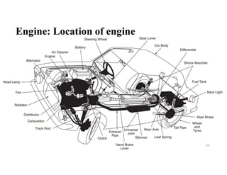
- 1. Engine: Location of engine 114
- 2. Cylinder arrangement • Construction details • Cylinder block • Cylinder head • Cylinder liners • Piston • Piston rings • Piston pin • Connecting rod • Crankshaft • Valves 115
- 3. Cylinder arrangement • Three, four, five, six, eight and twelve cylinders are used in car engines. • Buses and trucks use twelve and sixteen cylinder engines. • The engine cylinders can be arranged in the following ways (a) In a row (in-line) (b) In two rows or banks set at an angle (V-type) (c) In two rows, opposing each other (flat, or pancake) 116
- 5. Cylinder arrangement: Construction details • The cylinder of the internal combustion engine is the working chamber of the volumetric displacement. During engine operation, the internal and external parts of the cylinders experience different heating. • The inside part of the cylinder is a sleeve or cylinder liner. • The outer part of cylinder is the motor cooling jacket. 118
- 6. a – without cylinder liner, but with short insert; b, c – with wet cylinder liner; d – with wet cylinder liner and short insert; 1 – Cylinder block; 2 – motor cooling jacket; 3 – insert; 4 – cylinder liner; 5 – seal rings; 6 – anti-cavitation ring. 119
- 7. What is Cylinder Block? • An engine block is a structure that contains cylinders, and other parts of an internal combustion engine. • In old engines, the engine block has only the cylinder block, to which a separate crankcase was attached. • In modern engines, the engine block consists of the crankcase integrated with the cylinder block as a single component, giving a rigid structure. • Engine blocks also often include elements such as coolant passages and oil galleries. 120
- 8. Cylinder Block • The cylinder block, cylinder head, and crankcase are the three parts that form the foundation and main stationary body of an automobile engine. • They serve as support an enclosure for moving parts. • The cylinder block may also have a separate crankcase for the crankshaft, which is limited to larger engines, marine, and stationary engines. • A separate aluminum crankcase would result in saving weight as well as enable cheaper and quicker replacement. 121
- 9. Parts of Cylinder Block 1. Cylinders 2. Oil passages and galleries 3. Deck 4. Crankcase 5. Head studs 6. Core plugs 7. Water pump mounting 8. Oil filter 122
- 10. 123
- 11. 1. Cylinders : Cylinders are the parts in which the movement of the piston takes place. They are generally made of large size and have holes to form a seal with the piston. The number of cylinders holds the power and size of the engine. 2. Oil Passages and Galleries: These are essential components of the cylinder block for lubrication purposes. These provide oil to reach the cylinder head and crankshaft. 3. Deck : This is the top surface of the block where the end of the cylinder remains. 4. Crankcase: This component houses the crankshaft and is found under the modern engine block. 5. Head Studs: These are typically manufactured from a round rod of alloy steel. Threads are applied at both ends. This allows a tighter fit in the block, which prevents the stud from loosening when the stud nut is removed. 6. Core Plugs : A core plug is a cap of the engine block at the end of a coolant passage, which is used to prevent leakage of water or coolant from the engine. 7. Water Pump Mounting : A water pump is provided on the side of a cylinder block in housing coupled with a coolant casing. 8. Oil Filter : It is typically located either on the flank or under the engine block. There is an oil filter that keeps as many contaminants out of the lubricant that circulates the engine. 124
- 12. Material Used in Cylinder Block • The cylinder block is usually made from gray cast iron, and sometimes with the addition of nickel and chromium. • Some blocks are cast from aluminum, in which cast iron or steel sleeves are used. • For most engines, cast iron has been found to be a satisfactory cylinder wall material, as it has better wearing qualities. • In some small engines, the cylinder walls are placed with chromium, a very hard metal, to reduce wall wear and to increase their service life. • Tests are being carried out on high silicon-aluminum alloys to determine their possibilities as a material for cylinder block and crankcases. These alloys have a low coefficient of thermal expansion and high wear resistance. 125
- 13. Functions of Cylinder Block • The L-head engine blocks contain openings for the valves and valve ports. • The bottom of the block also supports the crankshaft and oil pan. • On most engines, the camshaft is supported in the cylinder block by bushing that fits into machined holes in the block. • In L-head inline engine, the intake and exhaust manifolds are connected to the side of the cylinder block. • On I-head engines the manifolds are joined to the cylinder head. Other parts attached to the block include the water pump (at the front), timing gear or timing chain cover (at the front), flywheel and clutch housing (at rear), ignition distribution, and fuel pump. 126
- 14. Types of Cylinder Block • Engine blocks are classified according to the size of the engine cylinders. 1. V-engine cylinder 2. Inline cylinder 3. Opposed engine or Boxer engine cylinder 127
- 15. V-engine Cylinder • This is the modern engine cylinder and is widely used nowadays. • In this configuration, the engines are provided in two rows. • These two rows are placed at an angle to each other. • The angle V is kept between 15° to 20°, as a larger angle makes it more difficult to balance the engine. • These are difficult to balance with the counterweight on the crankshaft. • There are different types of v engines, V16s, V8s for heavy vehicles, and V4s for small motorcycles are used as cylinder blocks. 128
- 16. Inline Cylinder • An inline engine is a type of cylinder block, in which a series of cylinders are arranged in such a way that they run in a single line. • Vehicles with this type of cylinder block operate smoothly. • They are mostly used where high rpm is needed. • It is often used in passenger cars. 129
- 17. Opposed Engine or Boxer Engine Cylinder • The Boxer engine is a flat pressed V engine. • In this engine cylinder, the blocks coming in two rows of two cylinders are set as opposed to each other. • They are also known for pancake engines. • They require very little headroom as the engine compartment can be very small. • These are commonly seen on 4 cylinder Volkswagen engines. • In addition, they are also employed on Porsche and Subaru and some other high-speed engines. 130
- 18. Problems of Cylinder Block • When cylinder blocks continue to operate, they sometimes break or wear out. • what are the problems that make them worse. 1.Leakage of external engine coolant 2.Worn or cracked cylinder 3.Porous engine block 131
- 19. 1. Leakage of External Engine Coolant: This leak could be from the water pump, radiator, heater core, or a loose hose. Sometimes it can also be due to engine block because of cracks. 1. Worn or Cracked Cylinder: After the cylinder has been in operation for a long time, wear inside the cylinder is a common problem. This can damage the smooth machined wall and affects the sealing by piston rings. It can be avoided by increasing the bore size. 1. Porous Engine Block: This is usually caused by contaminants that enter the metal. This often happens while the manufacturing process is going on. You can’t avoid this problem because that’s where the cylinder block originated. 132
- 20. Cylinder head What is a Cylinder Head? • A cylinder head is the cast metal part that covers the top part of a cylinder. • The cylinder head mounts on the cylinder block or engine housing. 133
- 21. 134
- 22. Cylinder Head Function • What is the function of cylinder heads in car engines? • Provide the mounting structure for various components such as the inlet and outlet exhaust valves and ducts, spark plugs, injectors, and (in some head designs), the camshaft. • Contain the passages for coolant, oil, and combustion gases • Dissipate the heat produced by the engine and, therefore, produce cooling • Act as the combustion chamber seal and the engine’s mechanical control powerhouse • Take the compression resulting from combustion pressure 135
- 23. • A cylinder head contains intake air, exhaust, Copland, and oil passageways. • One of the functions of a cylinder head is cooling the engine. The head achieves that using two main methods; water or air. • Water-cooled heads are the most popular, and many modern engines are of this type. • Air-cooled cylinder heads use large fins that fan the air to bring about cooling. 136
- 24. Cylinder Head Materials and Manufacturing • Auto cylinder heads are cast from molten metal. • Usually, manufacturers use the LFC , lost-foam casting, for the cylinder head casting. • The method uses polystyrene foam to produce the required pattern. • Cylinder heads can be made from iron or aluminum. • It depends on the required performance, durability, and other factors. Each material offers specific advantages that suit particular situations. • Aluminum cylinder heads • Iron cylinder heads 137
- 25. Aluminum cylinder head Iron cylinder heads- 138
- 26. Aluminum cylinder heads- • Aluminum produces lightweight heads that also dissipate heat more efficiently. • They give better fuel economy and heat transfer, aluminum heads are often used in performance and race cars. • In these cars, weight saving and rapid engine cooling are necessary features. • Most gasoline engines use aluminum cylinder heads. 139
- 27. Iron cylinder heads- • Iron cylinder heads are less expensive than those made from aluminum. • They are also high-strength and durable. • Iron heads also transfer heat poorly and do not fit demanding applications such as race cars. 140Slide 115: Cylinder arrangement
- 28. Cylinder arrangement - Cylinder liners • Cylinder liners are casting from high strength cast iron or special steels. • Sometimes aluminum cylinder liners are plating with chrome. 141
- 29. Cylinder Liner Defects The cylinder liners wear out due to friction between the piston and the mirror (inner cylinder wall). As a rule, increased wear may occur by the following reasons: – Not enough motor oil on the cylinder liners walls; - Engine did not work for a long time, and all the motor oil was drained in the crankcase; – Use of inappropriate viscosity motor oil; – The main causing of corrosion is use of water as a coolant; – Chips and scratches occur due to improper installation, dismantling (all actions for shooting cylinder liners must be carried out according to the rules with a special puller); – The engine is not used correctly. Slide 115: Cylinder arrangement142
- 30. Piston • A piston of an internal combustion engine is in the form of an inverted bucket shape and it is free to slide in the cylinder barrel. • The gas tightness is secured by means of flexible piston rings, which are in the grooves of the piston. • These grooves are cut in the upper part of the piston. 143
- 31. Functions of Piston 1. It forms a moveable wall of the combustion chamber. 2. It transmits turning force to the crankshaft via the connecting rod. 3. It functions like a crosshead and transmits side thrust, which is due to the angularity of the connecting rods, to the cylinder walls. 144
- 32. Qualities and Requirements of Piston 1. It must be strong enough to withstand high pressure caused due to the combustion of fuel. 2. It must be very light in weight to have minimum primary and secondary forces, which are caused due to the inertia forces of the reciprocating masses. A light piston permits higher speed of the crank. 3. The piston material must be a good conductor of heat so that detonation is suppressed, and higher compression ratio is possible to get fuel economy. 4. The piston operation must not be noisy. 5. The piston must be of less coefficient of expansion. 145
- 33. Piston Temperatures at Various Stages • It has been found by experiments that the maximum temperature produced is in the centre of the piston head, and the temperature decreases towards the edge of the piston head, and also decreases rapidly down side of the piston. • Most of the heat is passed into the cylinder block at the ring belt, and some temperature drop takes place from the skirt. 146Slide 115: Cylinder arrangement
- 34. PISTON RINGS • Piston rings are those rings which are fitted in the grooves provided in pistons • Piston rings are the ones that completely seal out the cavity formed between the piston and cylinder • Piston rings are not completely closed and are provided with a gap at the ends. • The gap allows the rings to fit over the piston and lets the rings expand without breaking. When the piston and piston rings expand with excessive heat, the ring gap becomes smaller 147
- 35. Types and Forms of Piston rings • Generally, there are two forms of gaps provided in piston rings: (a) straight or normal gap (b) diagonal or scarf gap • Two types of piston rings are widely used: 1. Compression ring 2. Oil control ring The compression ring serves two purposes, viz. (i) to seal the combustion chamber and (ii) to provide a path for heat transfer from the piston to the cylinder walls. This provides effective cooling. 148
- 36. 149
- 37. 150
- 38. 151
- 39. • The groove or slot cut on the circumference of the oil ring is also shown clearly. • Radial holes are drilled in the oil ring so that oil collected in the ring groove can pass in the piston ring groove. 152
- 40. 153
- 41. 154
- 42. Functions of Piston Rings 1. The piston rings seal the passage inside the cylinder 1. They provide a path for conducting heat from the piston head to the cylinder walls. 1. Piston rings scrap the excess oil from the cylinder walls and only a thin film of oil is left to lubricate the piston rings. 155
- 43. Piston Ring Joints • The oil control and compression rings usually butt together with a joint called a butt gap. • In a two-stroke cycle engine, the ends of the rotating ring could move into a cylinder part and cause breakage. • Most two-stroke cycle pistons therefore, have a pin in the piston groove that prevents the ring from rotating. 156
- 44. 157
- 45. 158
- 46. PISTON PIN • A piston pin is also known as a wrist pin because of its similarity in construction with human hand and arm joint. • A piston pin is a link for connecting the piston and the connecting rods. • The piston pin is fitted in the bosses which are in the piston. • The small end of the connecting rod is accommodated in between the piston bosses. 159
- 47. Piston Pins • These pins can withstand high temperature, heavy loads, and bending force. 160
- 48. 161
- 49. • The ends of the circlip ring are pressed and inserted in the piston boss, and then released in the groove made for this ring. • Piston pins are made of casehardening steel, either plain carbon steel, nickel steel or chrome-nickel steel. • The pins are designed to work as bearing journals. 162
- 50. Types of Piston Pins • Types of pins incorporated in pistons used in engines. 1. fixed pin, 2. full-floating pin and 3. semi-floating pin. • The fixed or anchored pin connects the piston with a screw running through one of the bosses while the linking rod vacillates on the pin. • Full floating pin rotates inside the connecting rod and the bosses whereas the semi-floating pin is fixed to the linking rod and turn in the bosses eventually. 163
- 52. Connecting Rod • The connecting rod is a connection between the piston and a crankshaft. • The small end of the connecting rod is connected to the piston pin and the big end to the crank pin. • The purpose of the connecting rod is to convert the linear motion of the piston into the rotary motion of the crankshaft. • A connecting rod with a tension load is made of forged steel, cast steel, or fabricated steel. • Rods with a compression loading are cast nodular steel or aluminum alloy.165
- 53. Connecting Rod • The connecting rod consists of an I-beam cross-section and is made of forged steel. • Aluminum alloy is also used for connecting rods. • The lighter the connecting rod and piston, the greater the resulting in power and the lesser the vibration because the reciprocating weight is less. • The connecting rod carries the power thrust from piston to the crankpin and hence it must be very strong, rigid and also as light as possible. 166
- 54. Parts of Connecting Rod 1. Small End 2. Big End 3. Bushing 4. Bearing inserts 5. Bolt and Nut 6. Shank 7. Wrist pin or Gudgeon pin 8. Piston 9. Bearing cap 167
- 55. 1. Small End • The end at which the connecting rod is attached to the face of the piston pin is known as the small end of the connecting rod. 2. Big End • The end at which the connecting rod is attached to the side of the crank pin is known as big end of the connecting rod. 168
- 56. 3. Bush Bearing • Both ends of the connecting rod are fixed with a bush bearing. A phosphor bronze bush is fitted with the solid eye is attached to the small end of the connecting rod. • The Big end is attached to the crankpin. The end is divided into two parts and is supported over the crank bearing shell. 4. Bearing Insert • In the big end of the connecting rod, there is a bearing insert that is connected to the bearing cap, it is known as a bearing insert. These are made in two parts that fit together on the crankshaft. This is the position where the connecting rod travels along the reverse direction. 169
- 57. 5. Bolt and Nut • After the connecting rod is fitted with the crank at the bottom, both sides of the big ends are fastened by some bolts and nuts. Thus, by combining these all components the connecting rod is ready to use. 6. Shank • Furthermore, each of the bolt and nuts are employed to connect both the connecting rod and bearing cap. And a section beam is applied it is known as shank. The section of the rod may be rectangular, tubular, and a circular section. • The connecting rod length lies on the ratio of (l/r) Where, I = is the length of the shank or beam r = is the radius of the shank. 170
- 58. 7. Wrist Pin or Gudgeon pin • The engine piston is connected to the connecting rod with the help of a hollow hardened steel tube called wrist pin. It is also known as gudgeon pin. Wrist pin goes through the short end of the connecting rod and pivots on the engaged piston. 8. Piston • The piston is connected to the crankshaft with the help of a connecting rod, which is usually shortened to the rod or Conrod. The purpose of the piston is to work as a movable plug in the cylinder, which forms the bottom of the combustion chamber. 9. Bearing Cap • Shell bearings have an adjustment for wear, but it controls the running and the side clearance allows the bearing cap to be tightened correctly. 171
- 59. Construction and Functions of Connecting Rod • There are two types of ends small end and big end bearings. • The big end is split at right angles to its length as at (a) or at an angle as at (b), in order that it may be assembled on the crankpin. • Modern engines do not have bearing metal fused to the bore of a big end, but it uses separate low carbon steel bearing shells. 172
- 60. Construction and Functions of Connecting Rod • The small end is usually a solid eye fitted with a phosphor bronze bush and a screw to close the eye around the pin. • All the connecting rods in an engine must be of equal weight otherwise noticeable vibration may occur. • In the assembly, the connecting rods and caps are individually matched to each other. 173
- 61. Types of Connecting Rod 1. Plain type rod 2. Fork and blade rod 3. Master and slave rod 4. Billet conrods 5. Cast rods 6. Forged rods 7. Powered metal conrods 174
- 62. 1. Plain Type Rods • The plain type of connecting rod is used in inline and opposed engines. • The big end of the connecting rod is attached to the crankpin and fitted with a bearing cap. • The bearing cap is mounted by a bolt or stud at the end of the connecting rod. • The connecting rod must be replaced in the same cylinder and in the same relative position to maintain proper fit and balance. 175
- 63. 2. Fork and Blade Rods • These types of connecting rod are used on V-twin motorcycle engines and V12 aircraft engines. • In each pair of engine cylinders, a “fork” rod is divided into two parts at the big end and a “blade” rod is tapered from the opposing cylinder to fit this gap in the fork. • This system eliminates the rocking couple that occurs when the cylinder pairs are balanced along with the crankshaft. • In the big-end bearings type of arrangement, the fork rod has a single wide-bearing sleeve that extends over the entire width of the rod, including the central gap. • The blade rod then runs directly outside this sleeve, not on the crankpin. This causes the two rods to move back and forth, this reducing the force on the bearing and the surface speed. But, the bearing speed also reciprocates instead of continuously rotating, which is a major problem for lubrication. 176
- 64. 3. Master and Slave Rods • Radial engines typically use master-and-slave connecting rods. • In this system, the one piston consists of a master rod with a direct attachment to the crankshaft. Other pistons connect their connecting rods to the rings surrounding the edge of the master rod. • The disadvantage of master-slave rods is that the stroke of the slave piston is slightly larger than that of the master piston, which increases the vibration in the V-type engine. 177
- 65. 4. Billet rods • Billet connecting rods are designed from steel or aluminum. • Compared to other types of connecting rod, they are lighter, stronger, and longer in lifespan. • It is commonly used in high-speed vehicles. • It is sometimes designed to reduce stress risers and ease into the natural grain of the billet material. 178
- 66. 5. Cast Rods • These types of connecting rod are preferred and designed by manufacturers because they can capable of handling the load of a stock engine. • Cast rods require low cost to produce and cannot be used in applications of high horsepower. • The cast rods have a noticeable seam in the middle that separates them from the forged type. 179
- 67. 6. Forged Rods • These types of connecting rod made by forcing a grain of material to the shape of the end. • Depending on the required properties the material may be steel alloy or aluminum. • Commonly used steel alloys are chrome and nickel alloy to increase the strength of the connecting rod. 180
- 68. 7. Powered Metal Conrods • It is prepared with a metal powder mixture that is pressed into the mould and heated to a high temperature. This mixture made into a solid form. • It may require light machining but the product basically comes out of a finished product mould. • Conrods of powder metal are less costly than steel and they are stronger than cast rods. 181
- 69. Faults of Connecting Rods • Following are the faults of a connecting rod: 1. Fatigue 2. Hydrolock 3. Over revving 4. Pin failure 182
- 70. 1. Fatigue • Fatigue often occurs because the compression and stretch of the rod happen most of the time during the process. • Eventually, this causes to wear of the rod till it gets breaks. • Lack of oil and the presence of dirt in the engine can exacerbate this problem. • This happens when cheap parts or wrong parts are used. 183
- 71. 2. Hydrolock • Hydrolock occurs when water enters the piston chamber causing deformation of the connecting rod. • This may occur when vehicles pass through a flooded road. • A little drop of water in the cylinder can produce knocking or tapping in the engine. • That can be easily corrected. But, if there is too much water in the cylinder, the spark is all over the place for a period of time, causing the cylinder rod to tilt or break. 184
- 72. 3. Over Revving • That occurs in new and high-performance engines. • If the tachometer displays a red color, it indicates that the position of the connecting rod is in danger. • This is because of forces working on the con rod rise dramatically at higher revolutions. 4. Pin Failure • Sometimes the piston pin is also damaged and results in catastrophic engine failure. • This occurs when the connecting rod moves into the engine block or when the crankshaft is bent. • In some engines, It can cause heavy power loss. • The engine stops immediately when the pin breaks due to this problem. • There is a possibility that the engine has survived, otherwise, a total breakdown may occur. 185
- 73. Applications of Connecting Rods • It is a part of a piston engine that connects the piston to the crankshaft. • The connecting rod converts the reciprocating motion of the piston to the rotation of the crankshaft. • In the modern era, all types of machines inevitably depend on pistons, connecting rods, and crankshafts. • These components are needed for the precise functioning of the internal combustion engine. 186
- 74. Crank Shaft • The crankshaft is a moving part of the internal combustion engine (ICE). • It’s main function is to transform the linear motion of the piston into rotational motion. • The pistons are connected to the crankshaft through the connecting rods. • The crankshaft is mounted within the engine block. • The pistons, connecting rods and crankshaft together form the crank mechanism. 1.Pistons 2.Connecting rods 3.Flywheel 4.Crankshaft 187
- 75. Crankshaft The secondary function of the crankshaft is to transmit power to other engine systems: • valve timing • oil pump • cooling (water) pump • air conditioning compressor • alternator, etc. 188
- 76. Crankshaft • The crankshaft is fitted into the engine block through it’s main journals. • The connecting rods are fixed on the conrod journals of the crankshaft. • On opposite sides of the conrod journals the crankshaft has counterweights which compensates outer moments, minimises internal moments and thus reduces vibration amplitudes and bearing stresses. • At one end of the crankshaft the flywheel is connected and on the other end the valve timing gearing. 189
- 77. Crankshaft • The number of main journals and conrod journals depends on the number of cylinders and the type of the engine (V-type, straight, etc.). • On both main journal and conrod journals, the crankshaft has lubrication orifices (oil bore) through which oil flows when the engine is running. 1.Control side or drive end 2.Counterweights 3.Main bearing journal 4.Conrod journal 5.Flywheel side/force transfer 6.Oil bore 190
- 78. 191
- 79. • Two types of crankshaft are produced, cast and forged. The counterweights can be also forged directly onto the crankshaft or bolted-on (fixed with threaded bolts). • All the pistons of the internal combustion engine are transmitting their forces to the crankshaft. • From the mechanical point of view, the crankshaft has to withstand high torsional forces, bending forces, pressures and vibrations. Crankshaft 192
- 80. 193
- 81. Crankshafts for Multi-cylinder Engines (Firing Order) • To achieve better balancing of the dynamic (primary and secondary) forces and their couples, the multi-cylinder engines have even number of cylinders, i.e. 4 cylinder, 6 cylinder, 8 cylinder engines. 194
- 82. 195
- 83. 196
- 84. Valves •Engine valves are mechanical components used in internal combustion engines to allow or restrict the flow of fluid or gas to and from the combustion chambers or cylinders during engine operation. 197
- 85. Valves • Engine valves are common to many types of combustion engines, whether they run off a fuel such as gasoline, diesel, kerosene, natural gas (LNG), or propane (LP). • Engine types vary by the number of cylinders which are the combustion chambers that generate power from the ignition of fuel. • They also vary by the type of operation (2-cycle or 4-cycle), and by the design placement of the valves within the engine [overhead valve (OHV), overhead cam (OHC), or valve in block (VIB)]. 198
- 88. Engine Valve Nomenclature • Most engine valves are designed as poppet style valves because of their up and down popping motion and feature a conical profile valve head that fits against a machined valve seat to seal off the passage of fluids or gases. • They are also called mushroom valves because of the distinctive shape of the valve head. 201
- 89. Valves - Engine Operation • The two primary elements are the valve stem and the valve head. • The head contains a fillet that leads into a seat face that is machined at a specified angle to match the machining of the valve seat to which it will match. • The seating of the valve face to the valve seat is what provides the seal for the valve against combustion pressure. • The valve stem connects the valve to the mechanical elements in the engine that operate the valve by creating a force to move the stem against the seating pressure provided by a valve spring. • The keeper groove is used to hold the spring in position, and the tip of the valve stem is repeatedly contacted by a rocker arm, tappet, or lifter that actuates the valve. 202
- 90. Valves - Engine Operation • Four stroke or four-cycle internal combustion engines make use of two primary types of valves – the intake valve and the exhaust valve. • Intake valves are opened to allow the flow of an air/fuel mixture into the engine’s cylinders prior to compression and ignition, while exhaust valves open to permit the expulsion of exhaust gases from the combustion process after ignition has occurred. 203
- 91. Valves - Engine Operation • In normal operation, a crankshaft in the engine to which the pistons are attached is tied to a camshaft as part of a valve train arrangement for the engine. • The movement of the crankshaft transfers motion to the camshaft through a timing chain, timing belt, or other geared mechanism. 204
- 92. Engine Valve Motion • The motion of the engine valves is driven by the camshaft of the engine, which contains a series of lobes or cams that serve to create linear motion of the valve from the rotation of the camshaft. • The number of cam lobes on the camshaft is equal to the number of valves in the engine. 205
- 93. Engine Valve Motion • Maintaining the proper valve clearance between the valve stem and the rocker arm or cam is extremely important for the proper operation of the valves. • If the valve clearance is too large, then the valves will open later than optimally and will close sooner, which can reduce engine performance and increase engine noise. • If the valve clearance is too small, valves will not close fully, which can result in a loss of compression. • Hydraulic valve lifters are self-compensating and can eliminate the need for valve clearance adjustments. 206
- 94. Engine Valve Materials • Intake valves, because of their lower operating temperatures, are typically made of materials such as chrome, nickel, or tungsten steel. • The higher temperature exhaust valves may use more heat resistant metals such as nichrome, silicon-chromium, or cobalt-chromium alloys. • Valve faces that are exposed to higher temperatures are sometimes made more durable by the welding of Stellite, which is an alloy of cobalt and chromium, to the valve face. 207
- 95. Engine Valve Materials • Other types of material used for the fabrication of engine valves include stainless steel, titanium, and tribaloy alloys. • In addition, coatings and surface finishes can be applied to improve the mechanical properties and wear characteristics of the engine valves. • Examples of this include chromium plating, phosphate plating, nitride coating, and swirl finishing. 208
- 96. Types of Engine Valves The primary types of engine valves include: 1. Monometallic engine valves 2. Bimetallic engine valves 3. Hollow engine valves 209
- 97. Monometallic engine valves • Monometallic engine valves, as their name implies, are fabricated from a single material that forms both the valve stem and valve head. • These types of engine valves provide both high heat resistance and exhibit good anti-friction capabilities. 210
- 98. Bimetallic engine valves • Bimetallic engine valves, also known as bimetal engine valves, are made by joining two different materials together using a friction welding process to create a valve that has austenitic steel on the valve head and martensitic steel for the valve stem. • The properties of each of these steels serve an optimal purpose, wherein the austenitic steel on the valve head provides high- temperature resistance and corrosion resistance, and the martensitic steel for the valve stem offers high tensile strength and abrasive wear resistance. 211
- 99. Hollow engine valves • Hollow engine valves are a special bimetallic valve that contains a hollow cavity that is filled with sodium. • The sodium liquifies as the valve temperature rises and is circulated by the motion of the valve, which helps dissipate heat from the hotter valve head. • The hollow design facilitates greater heat transfer through the stem than with solid valves because the martensitic stem material is a better conductor of heat than the austenitic head material. • Hollow valves are especially suited for use in modern engines that are delivering more power out of smaller, denser engine designs that have higher exhaust gas temperatures which solid valves are not capable of handling. 212
- 100. Hollow engine valves These higher exhaust temperatures are the result of several conditions, including: • A desire for a lean-burn combustion process that reduces greenhouse gas emissions • Engine designs with higher compression ratios and higher combustion pressures which offer greater efficiency • Integrated manifold designs that support turbochargers for more engine performance from smaller engines 213
- 101. Engine Valve Specifications • Stem diameter – the diameter of the engine valve stem • Stem length – the distance from the stem tip to the valve head • Seat angle – the angle cut of the valve head’s seat, measured in angular degrees, typical values being in the range of 20o – 60o • Valve materials – describes the material or materials used for the valve fabrication • Coatings – identifies any coatings or surface treatments applied to the base material of the valve, such as chrome plating, nitride, PVD, or ceramics, for example 214
- 102. Lubrication system: Types, Oil pumps, Filters • To supply lubrication oil between the moving parts is simply termed as lubrication. • Improper lubrication of the engine will cause serious trouble such as scored cylinders, dirty spark plugs, worn or burned- out bearings, misfiring cylinders, stuck piston rings, engine deposits and sludge and excessive fuel consumption. 215
- 103. Objects of Lubrication The primary objects of lubrication are as follows: 1. Reduce friction between the moving parts. 2. Reduce wear of the moving parts. 3. Act as a cooling medium for removing heat. 4. Keep the engine parts clean, especially piston rings and ring grooves, oilways and filters. 5. To absorb shocks between bearings and other engine parts, therefore, reducing engine noises and increasing engine life. 6. To form a good seal between piston rings and cylinder walls. 7. Prevent deposition of carbon, soot and lacquer. 8. Absorb and carry away harmful substances resulting from incomplete combustion. 9. Prevent metallic components from corrosive attack by the acid formed during the combustion process. 10. To resist oxidation which causes sludge and lacquers. 216
- 104. 217
- 105. Types of Lubrication System Following are the 6 main types of lubrication system: 1. Petrol system 2. Splash system 3. Pressure system 4. Semi-pressure system 5. Dry sump system 6. Wet sump system 218
- 106. Petrol System • In these types of the lubrication system, it is commonly used in the two-stroke petrol engines such as scooters and motorcycles. It is the simplest form of the lubricating system. For lubrication purpose, it does not have any separate part like an oil pump. • But the lubricating oil is added to the petrol itself during filling in the petrol tank of the vehicle in a specified ratio. When fuel enters the crank chamber during engine operation, oil particles go down into the bearing surfaces and lubricate them. The piston rings, cylinder walls, piston pins, etc. are easily lubricated in the same way. • If the engine is allowed to remain unused for a considerable time, the lubricating oil separates off from petrol and starts to clogging of passages in the carburettor, occurring in engine start problems. Thus is the main disadvantages of this system. 219
- 107. Splash System • In these types of lubrication system, the lubricating oil accumulates in an oil trough or sump. • A scoop or dipper is made in the lowest part of the connecting rod. • When the engine runs, the dipper dips in the oil once in every revolution of the crankshaft and cause the oil to splash on the cylinder walls. • This action affects engine walls, piston rings, crankshaft bearings, and large end bearings. • Splash system mostly works in connection with the pressure system in an engine, some parts being lubricated by splash system and the other by a pressure system. 220
- 108. 221
- 109. Pressure System • In these types of lubrication system, engine parts are lubricated under pressure feed. • The lubricating oil is stored in a separate tank or the sump, from which an oil pump receives the oil through a strainer and transfers it through a filter to the central oil gallery at a pressure of 2-4 kg/cm2. 222
- 110. Semi-pressure System • It is the combination of a splash system and pressure system of the lubrication system. • Some parts are lubricated by splash system and some parts by a pressure system 223
- 111. Dry Sump System • The system in which lubricating of oil collects in the oil sump is known as a wet sump system as a pressure system. • The system in which the lubricating oil is not located in the oil sump is known as the dry pump system. • In this system, the vanes sweep the oil from the inlet to the outlet side. 224
- 112. Wet Sump System • In this system, oil is transported to various engine parts with a sump strainer. • In this wet sump system, oil pressure is of about 4 to 5 kg/cm2. After lubrication, the oil is carried back to the oil sump. 225