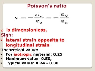
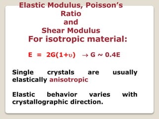
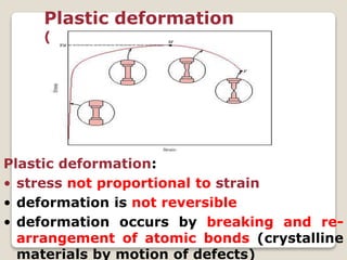
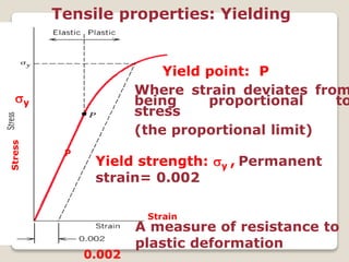
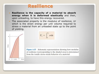
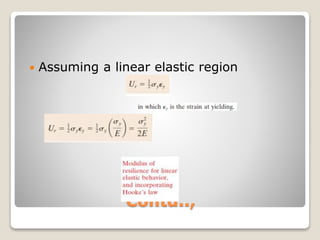
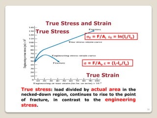
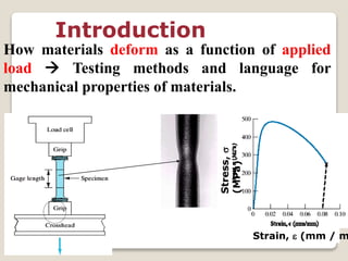
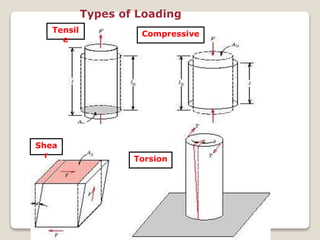
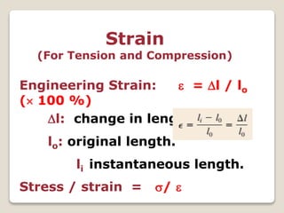
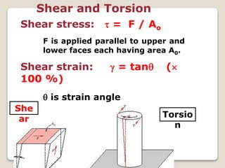
This document discusses the mechanical properties of materials. It defines mechanical properties as how materials behave when subjected to stresses and strains from applied forces. It explains different types of loading like tension, compression, and shear that materials can experience. It also defines concepts like stress, strain, elastic deformation, plastic deformation, and viscous deformation. Different material behaviors are described like elastic, plastic, elastoplastic, and viscoelastic. The document also discusses properties such as modulus of elasticity, Poisson's ratio, yield strength, ductility, toughness, resilience, hardness, and factors of safety in material design. Testing methods for mechanical properties and examples of stress-strain curves are provided.


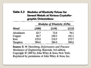
![• The physical properties of some
substances depend on the
crystallographic direction in which the
measurements are taken.
• For example, the elastic modulus, the
electrical conductivity, and index of
refraction may have different values in
the [100] and [111] directions.
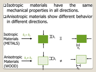
• This directionality of properties is
termed as anisotropy, and it is
associated with the variance of atomic
or ionic spacing with crystallographic
direction.
• Substances in which the measured](https://image.slidesharecdn.com/enggmatchapter5-191022104015/85/Engg-mat-18-320.jpg)