Download as PDF, PPTX


![PP
X
L
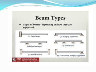
b2 b1bx
x
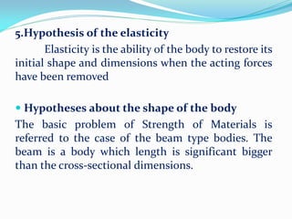
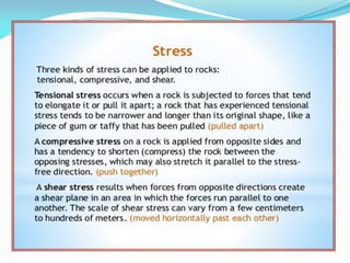
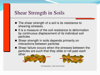
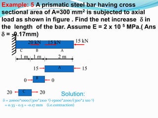
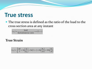
Take b1 = 200mm, b2 = 100mm, L =
500mm
P = 40kN, and E = 200GPa, t = 20mm
δL= PLloge(b1/b2) / [Et(b1 – b2)]
= 40000*500loge(200/100)/[200000*20 *100]
= 0.03465mm
Q. Calculate extension of Tapering bar of
uniform thickness t, width varies from b1 to
b2:-
P/Et ∫ x / [ (b1 + k*X)],](https://image.slidesharecdn.com/som-161003043456/85/Som-50-320.jpg)


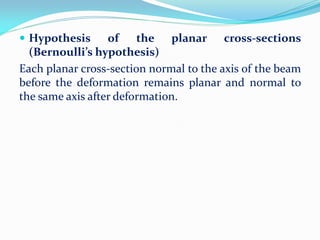
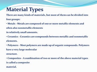
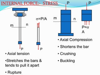
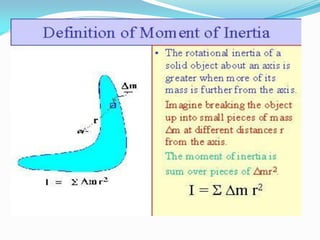
![GATE-1. Two identical circular rods of same diameter
and same length are subjected to same magnitude of
axial tensile force. One of the rods is made out of mild
steel having the modulus of elasticity of 206 GPa. The
other rod is made out of cast iron having the modulus
of elasticity of 100 GPa. Assume both the materials to
be homogeneous and isotropic and the axial force
causes the same amount of uniform stress in both the
rods. The stresses developed are within the
proportional limit of the respective materials. Which
of the following observations is correct?
[GATE-2003]
(a) Both rods elongate by the same amount
(b) Mild steel rod elongates more than the cast iron rod
(c) Cast iron rod elongates more than the mild steel rod
(d) As the stresses are equal strains are also equal in both
the rods](https://image.slidesharecdn.com/som-161003043456/85/Som-66-320.jpg)
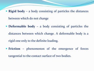
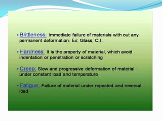
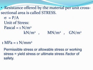
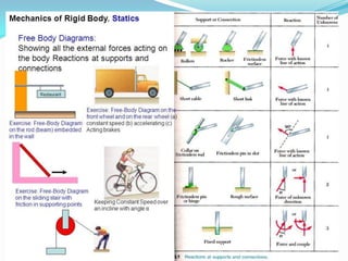
![A steel bar of 40 mm × 40 mm square cross-section is subjected to an axial
compressive load of 200 kN. If the length of the bar is 2 m and E = 200 GPa,
the
elongation of the bar will be: [GATE-2006]
(a) 1.25 mm (b) 2.70 mm (c) 4.05 mm (d) 5.40 mm
The ultimate tensile strength of a material is 400 MPa and the elongation
up to
maximum load is 35%. If the material obeys power law of hardening, then
the
true stress-true strain relation (stress in MPa) in the plastic deformation
range
is: [GATE-2006]
(a) σ = 540ε 0.30 (b) σ = 775ε 0.30 (c) σ = 540ε 0.35 (d) σ = 775ε 0.35
An axial residual compressive stress due to a manufacturing process is
present
on the outer surface of a rotating shaft subjected to bending. Under a given
bending load, the fatigue life of the shaft in the presence of the residual
compressive stress is: [GATE-2008]
(a) Decreased
(b) Increased or decreased, depending on the external bending load
(c) Neither decreased nor increased
(D)Increased](https://image.slidesharecdn.com/som-161003043456/85/Som-67-320.jpg)
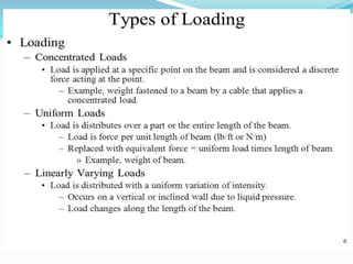
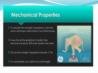
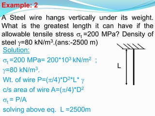
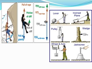
![A static load is mounted at the centre of a shaft rotating at uniform
angular
velocity. This shaft will be designed for [GATE-2002]
(a) The maximum compressive stress (static) (b) The maximum tensile stress
(static)
(c) The maximum bending moment (static) (d) Fatigue loading
Fatigue strength of a rod subjected to cyclic axial force is less than that
of a
rotating beam of the same dimensions subjected to steady lateral force
because
(a) Axial stiffness is less than bending stiffness [GATE-1992]
(b) Of absence of centrifugal effects in the rod
(c) The number of discontinuities vulnerable to fatigue are more in the rod
(d) At a particular time the rod has only one type of stress whereas the beam
has both
the tensile and compressive stresses.](https://image.slidesharecdn.com/som-161003043456/85/Som-68-320.jpg)
![A rod of length L and diameter D is subjected to a tensile load P. Which
of the following is sufficient to calculate the resulting change in
diameter?
(a) Young's modulus (b) Shear modulus [GATE-2008]
(c) Poisson's ratio (d) Both Young's modulus and shear modulus
In terms of Poisson's ratio (μ) the ratio of Young's Modulus (E) to Shear
Modulus (G) of elastic materials is: [GATE-2004]](https://image.slidesharecdn.com/som-161003043456/85/Som-69-320.jpg)


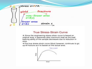


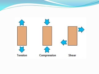


This document provides an introduction to strength of materials (SOM). It defines key terms like strength, stiffness, stability, and durability. It discusses the basic problem in SOM as developing methods to design structural elements that consider strength, stiffness, stability, and economy. It also outlines the main hypotheses in SOM, including the material being continuous, homogeneous, and isotropic. It then discusses different types of stresses like tensile, compressive, and shear stresses. It provides stress-strain curves for ductile materials and defines modulus of elasticity. Examples of calculating stresses and strains in structural elements are also provided.


