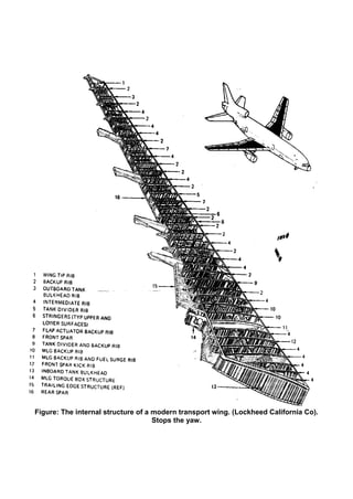
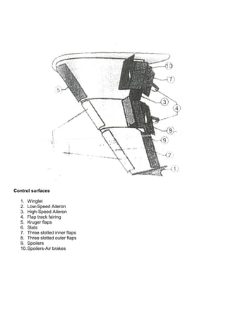
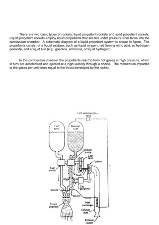
The document provides a summary of the historical development of aircraft, including different aircraft types (biplanes, monoplanes, triplanes), early propulsion methods (paddle wheels, steam engines, internal combustion engines), pioneering figures (Wright brothers, Cayley, Lilienthal), and materials used in aircraft construction over time (aluminum alloys, steel, titanium, composites). It discusses the advantages and disadvantages of biplane and monoplane configurations, as well as how materials and structures evolved with technological advances to enable modern aircraft. Key developments include the Wright brothers' successful powered flight in 1903 and their contributions to control surfaces and propellers.


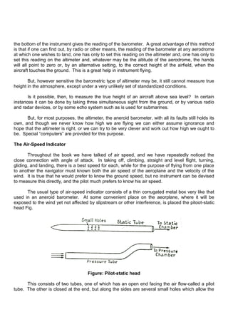

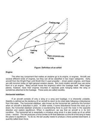
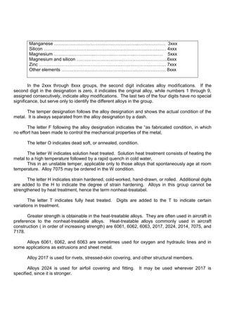
![Hydraulic Actuator and Electronic actuator system:
Brief summary of the invention:
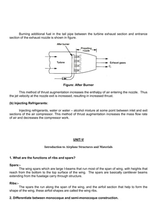
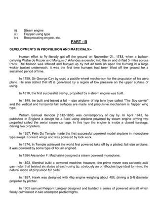
[0014] According to principles of the present invention, a backup system is provided that
has a local electric motor and pump for some or all of the hydraulic actuators. A local back up
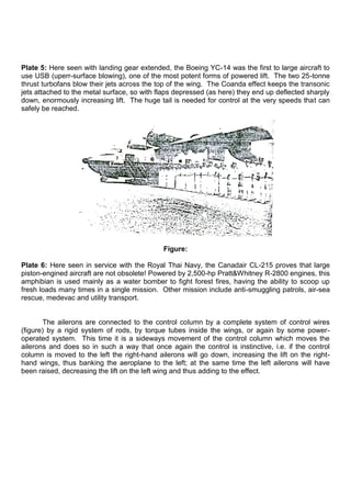
hydraulic actuator (LBHA) has two power sources, central hydraulic as primary and electrical as
backup. During normal operation, the hydraulic actuator receives pressurized fluid from one of the
central hydraulic systems and the fluid flow to the chambers is controlled by a servo valve. Failure
of the hydraulic system is detected by the local electronic controller that monitors the output signal
of a pressure sensor. When this observed pressure falls below a certain threshold, the local
electronic controller determines that this central hydraulic system has failed and t urns on the
electrical motor, which powers the local hydraulic pump to provide high pressure hydraulic fluid to
the hydraulic actuator via the servo value. The local electronic controller also uses the pressure
reading for closed – loop feedback control, and the pressure is maintained at the normal level.
Other types of monitoring and control schemes may also be used instead. In this manner, the
LBHA remains functional with electrical power following a partial or complete failure of the central
hydraulic system.
[0015] By coupling the LBHAs to appropriate flight control surfaces, the airplane remains
controllable with loss of all central hydraulic systems; therefore, the number of central hydraulic
systems can be reduced compared to using only conventional hydraulic actuators.
[0016] As explained in the background of the invention, some prior art approaches provide
a reduction in the number of hydraulic systems, namely EHA and EBHA, for example. A major
advantage that the LBHA offers over these prior art actuators is that it enables this reduction in the
central hydraulic system for airplanes with flight control surfaces which are controlled in an active
– active fashion. This is accomplished by overcoming both of the two major difficulties that have
been cited herein for the electric and hybrid actuators of the prior art, namely that of reduced
reliability and force fight.
[0017] The LBHA overcomes the reduced reliability problem by using the low – reliability
components only as backup following the failure of a central hydraulic system or during specific
phases of flight. The electrical part of the LBHA can be switched of during much of flight so the life
of the motor and pump is greatly extended. Therefore, even when the LBHA is used continuously
during normal operation, such as on an active- active surface, the operation is more reliable and
the life of the motor and pump are extended.
[0018] The force fight problem associated with coupling dissimilar actuators on a surface
and using them in an active – active fashion is resolved according to this invention by continuously
controlling the actuator in the same manner as a conventional hydraulic actuator and providing as
backup only alternate power source. The local motor and pump are upstream of the servo valve
and in parallel with the central hydraulic lines. A common servo value for the hydraulic actuator is
used under a unified electrical control system for both the central hydraulic system and the backup
system. This ensures that there is no substantial force fight when LBHA is used in an active –
active fashion with a hydraulic actuator or another LBHA on the same surface. This is because
during normal operation and operation following the failure of the central hydraulic system, the](https://image.slidesharecdn.com/elements-of-aeronautics-211109043501/85/Elements-of-aeronautics-37-320.jpg)
![LBHA is controlled in the same manner through the servo valve, with the only difference being the
source of hydraulic power, central or local.
[0019] In addition to enabling the reduction of hydraulic systems and resolving the problems
associated with applying electric or hybrid actuators of prior art in an active – active fashion, the
LBHA also offers other advantages. With the LBHA, the local pump can be a one – way pump
rather than a two – way pump, which, together with the motor and controller, is lower in weight and
cost, while having higher reliability. The local pump‟s role is to provide increased local pressure,
rather than also provide servo control of the system, thus simplifying the motor, the motor driver
and control device, and increasing the reliability of operation.
[0020] The inventive system also provides the advantage that during critical flight phases,
such as takeoff and landing, both the main system and the backup system can be in operation. In
the event of failure of the main system, the backup; system is already under power and is assisting
in the operation, so that there is no time lost for control while the backup system comes on. Check
values are provided between the central hydraulic system and the local backup system, permitting
both to operate at the same time when appropriate.
[0021] A further advantage is that the backup system has a separate power source, namely
electric power, so that increased availability of power is provided to the actuator. Because of this,
providing one LBHA in conjunction with at least one hydraulic actuator for a particular surface is
able to ensure that the likelihood of a complete loss of the power to position the surface correctly
is negligible. This may, for example, enable reduction in the number of actuators coupled to a
surface compared to only using conventional hydraulic actuators, while achieving and equivalent
or better level of safety. This may also enable smaller, lighter, and simpler individual actuators
than otherwise would have been possible.
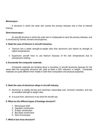
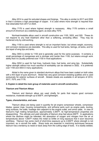
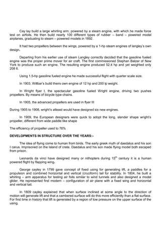
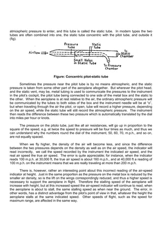
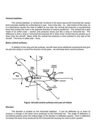
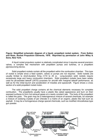
Flight instruments:
From Wikipedia, the free encyclopedia
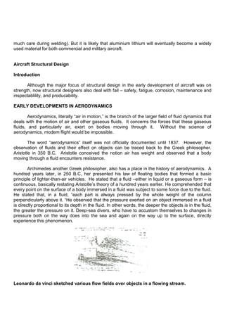
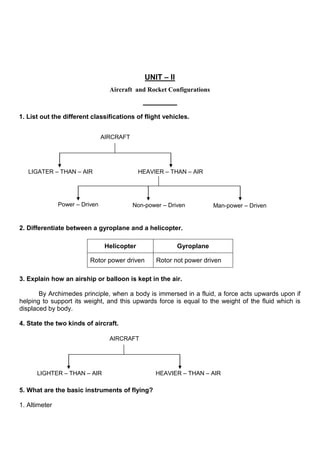
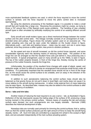
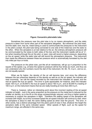
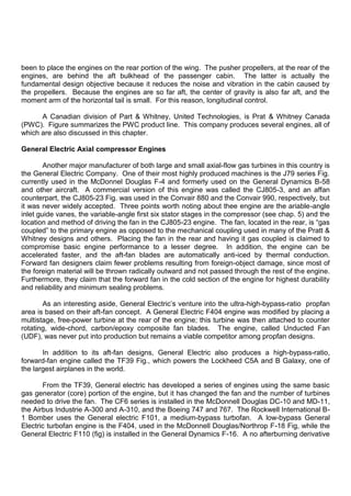
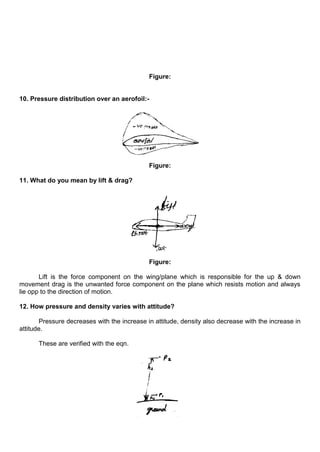
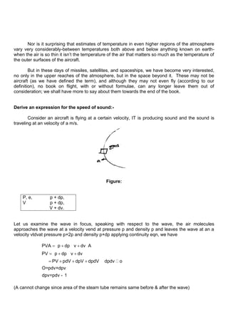
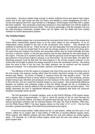
Most aircraft are equipped with a standard set of flight instruments which give the pilot information
about the aircraft‟s attitude, airspeed and altitude.
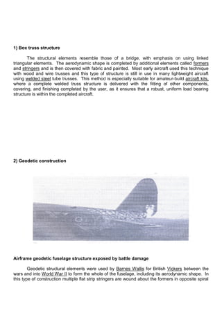
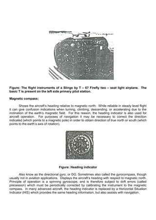
Figure: Six basic instruments in a light twin – engine airplane arranged in the basic – T.
From top left airspeed indicator, attitude indicator, altimeter, turn coordinator, beading
indicator, and vertical speed indicator.](https://image.slidesharecdn.com/elements-of-aeronautics-211109043501/85/Elements-of-aeronautics-38-320.jpg)
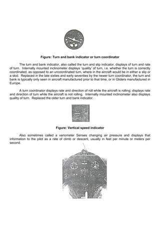
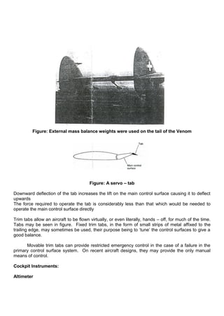
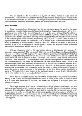
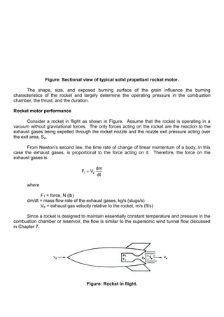
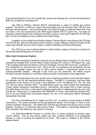
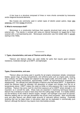
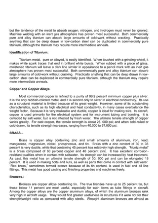
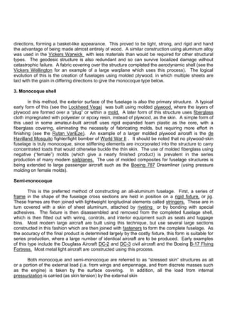
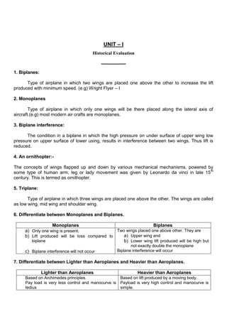
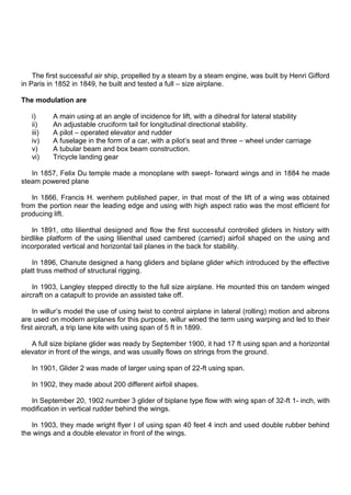
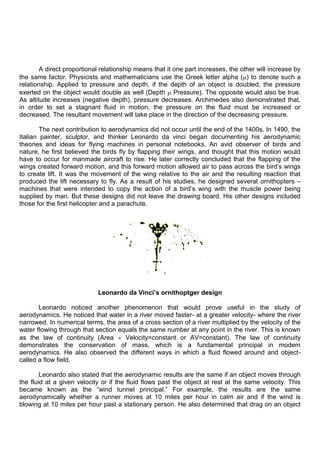
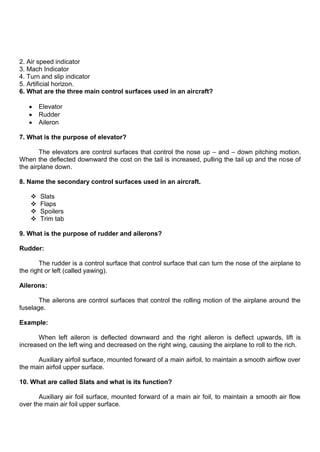
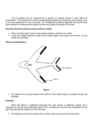
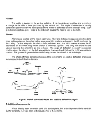
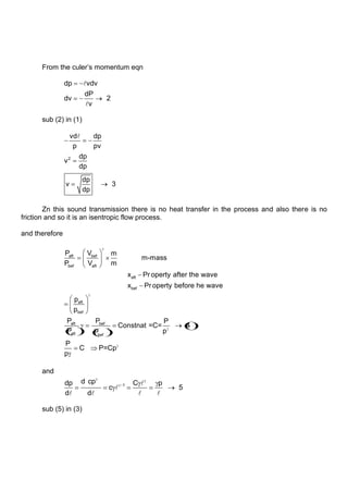
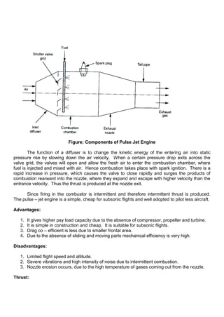
![Axial-Centrifugal Compressor Engines
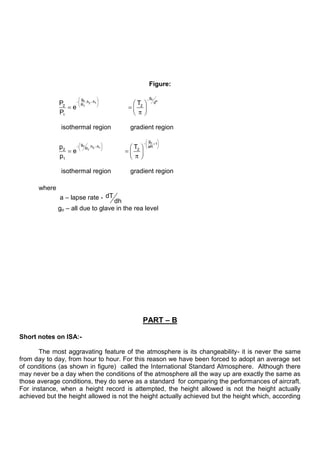
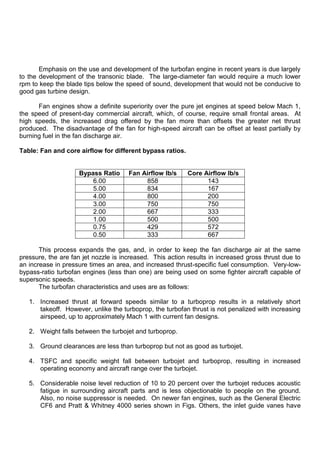
As a group, the axial-centrifugal-flow engines exhibit the greatest variability and design
innovation. The AlliedSignal Garrett ATF3 is a perfect example Fig. All of the various
permutations and combinations of compressor design, number of spools, type of combustion
chamber, single-shaft versus free-power turbine, location of the power-takeoff shaft, etc., can be
found on these engines.
An important producer of axial-centrifugal engines in this country is AlliedSignal Lycoming
Fig. their T53 and T55 series engines Fig, in their several versions, have been designed for wide
application in both conventional and rotary wing aircraft. Both engines use the same basic
concept and arrangement of parts; the main difference is in the number of compressor and free-
power turbine stages. The mechanically independent free-power turbine drives a coaxial through-
shaft to provide cold, front-end power extraction. A feature of these engines is the reverse-flow
combustion chamber design mentioned previously.
Two later engines developed by AlliedSignal Lycoming are the LTS/LTP (fig) series of small
turboshaft/turboprop engines and the ALF502 (Fig). At the time of this writing, most turbofan
engine fans are either coupled to one of the compressors or to a group of turbines independent of
the gas-generator compressor turbine(s). Either case requires a compromise, since the best
number of revolutions per minute (rpm) for the fan is, in most cases, lower than the best rpm for
the gas-generator compressor (core engine) or any turbine wheel. In the ALF502, the fan is
geared down, like the propeller on many piston engines, so the low pressure turbine and high-
bypass-ratio fan can each turn at an appropriate rpm.
The highly produced and used Pratt & Whitney Canada (PWC) PT6A engine also uses a
reverse-flow combustion chamber. On this machine, the air enters toward the rear and flows
forward, with the power takeoff at the front. It is currently in use on many twin engine aircraft in
business and commuter operation, including the Beech Starship, Beech King Air, Shorts 360, the
Piper Aircraft Corp. Cheyenne, Cessna Conquest, a few Bell helicopters, and several foreign
aircraft. The engine has also been used to power the STP Special at the Indianapolis 500 race.
Another interesting design from PWC, also incorporation a reverse-flow combustion chamber to
keep the engine short, is the JT15d fig. used on the Cessna Citation. As can be seen in this
chapter, many other engine manufacturers use the reverse-flow burner concept in their designs.
Allison Engine Company‟s bid for the small turbine market, the T63 (model 250) fig. has an
axial-centrifugal compressor (some variations of this engine use only a centrifugal compressor)
and incorporates many unusual design features. For example, it can be disassembled in minutes
with ordinary hand tools, contains a single combustion chamber, and has an interchangeable
gearbox. The axial part of the compressor is only about 4.5 inch (in) diameter, and the engine
weighs about 140 lb [64 kilograms (kg)] yet produces over 400 hp [298 kw] in some versions. The
turbo shaft variation of this engine is installed in the Hughes OH-6 Light Observation Helicopter
(LOH), the Bell Jet Ranger helicopter, and others. Figures 2-87 and 2-86 show two small
turbofans, with an axial-and centrifugal-style compressor: the Williams International FJ-44, which
powers the Cessna CitationJet, and the F107 Wr-400 used in the cruise missile.](https://image.slidesharecdn.com/elements-of-aeronautics-211109043501/85/Elements-of-aeronautics-66-320.jpg)
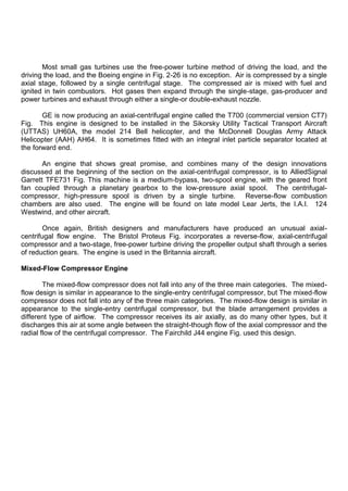
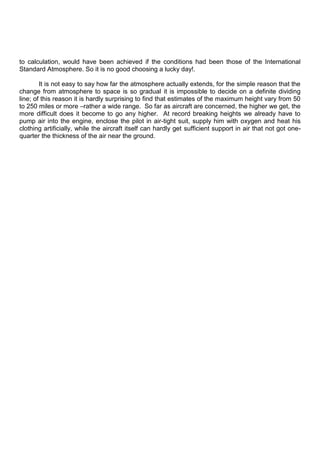
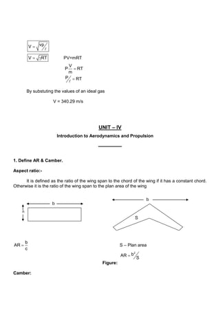
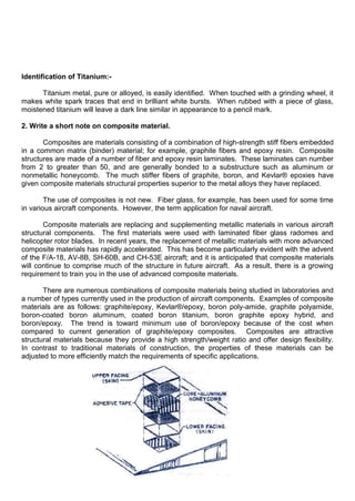
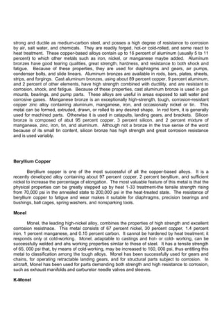
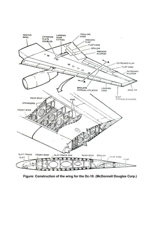
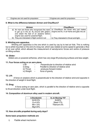
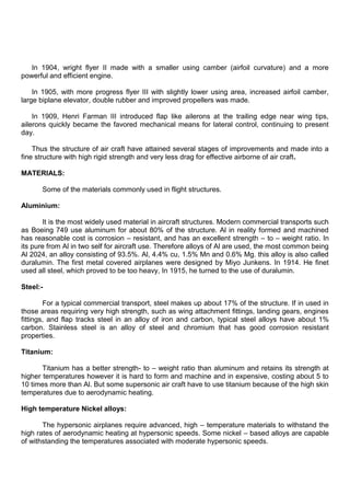
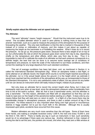
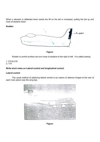
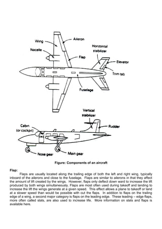
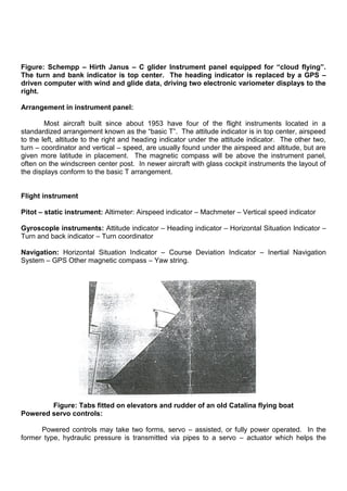
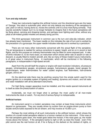
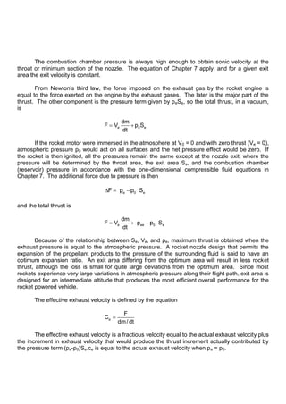
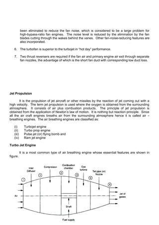
![Which deals with engine theory, points out that a turbojet derives its thrust by highly
accelerating a small mass of air, all of which goes through the engine. Since a high “jet” velocity is
required to obtain an acceptable amount of thrust, the turbine of a turbojet is designed to extract
only enough power from the hot gas stream to drive the compressor and accessories. All of the
propulsive force produced by a jet engine is derived from the imbalance of forces within the engine
itself Fig.
The turbojet characteristics and uses are as follows:
1. Low thrust at low forward speeds
2. Relatively high, thrust-specific fuel consumption (TSFC) at low altitudes and airspeeds, a
disadvantage that decreases as altitude and airspeed increase
3. Long takeoff roll
4. Small frontal area, resulting in low drag and reduced ground-clearance problems
5. Lightest specific weight (weight per pound of thrust produced)
6. Ability to take advantage of high ram-pressure ratios
These characteristics suggest that the turbojet engine would be best for high-speed, high-
altitude, long-distance flights.
The Turboprop Engine
Propulsion in a turboprop engine is accomplished by the conversion of the majority of the
gas-steam energy into mechanical power to drive the compressor, accessories, and the propeller
load. Only a small amount (approximately 10 percent of “jet” thrust is available in the relatively
low-pressure, low-velocity gas stream created by the additional turbine stages needed to drive the
extra load of the propeller.
The turboprop characteristics and uses are as follows:
1. High propulsive efficiency at low airspeeds, which results in shorter takeoff rolls but falls off
rapidly as develop high thrust at low airspeeds because the propeller can accelerate large
quantities of air at zero forward velocity of the airplane. A discussion of propulsive
efficiency follows in the next chapter.
2. More complicated design and heavier weight than a turbojet
3. Lowest TSFC
4. Large frontal area of propeller and engine combination that necessitates longer landing
gears for low-wing airplanes but does not necessarily increase parasitic drag
5. Possibility of efficient reverse thrust
These characteristics show that turboprop engines are superior for lifting heavy loads off
short and medium-length runways. Turboprops are currently limited in speeds to approximately
500 mph [805 km/h], since propeller efficiencies fall off rapidly with increasing airspeeds because
of shock wave formations. However, researchers in the Hamilton Standard division of United
Technologies Corporation and others are trying to overcome, or extend, this limitation by
experimenting with small diameter, multibladed, wide-chord propellers, said to be more efficient
than the high-bypass-ratio turbofan, with a 20 percent reduction in thrust-specific fuel](https://image.slidesharecdn.com/elements-of-aeronautics-211109043501/85/Elements-of-aeronautics-77-320.jpg)
![Pressure thrust Fpr = (Pe – Pa ) Ae
Net thrust F = a f
. .
m m Ce - a
.
m u + Ae (Pe – Pa)
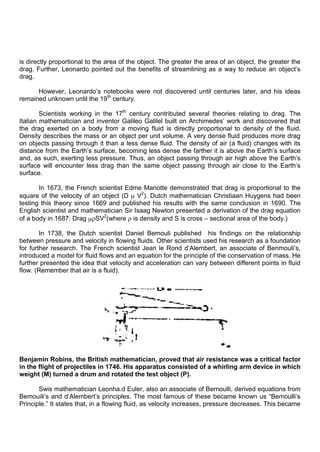
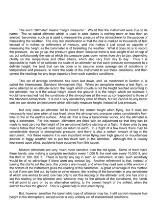
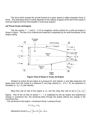
Propeller Thrust:
Figure shows the air flow takes place across the propeller of a turbo prop engine. The air
flow pattern before and after the propeller is shown in figure. A flow boundary similar to the walls
of a duct which separates the fluid at rest and fluid in motion.
Figure: Flow through a Turbo – Prop Engine
The pressure at section 1 – 1 and outside the boundary is ambient. Therefore, the thrust
on the propeller and the aircraft is due to the change in momentum flux between inlet and outlet
section.
The thrust on the propeller F = a
.
m (Cj – u)
Where Cj = Jet velocity and
u = flight speed
The flight to jet velocity ratio or effective speed ratio
j
u
C
Therefore, a j
j
. u
F m C 1
C
= a
.
m Cj [ 1 - ]](https://image.slidesharecdn.com/elements-of-aeronautics-211109043501/85/Elements-of-aeronautics-87-320.jpg)