WORKING PRINCIPLE OF
GENERATOR
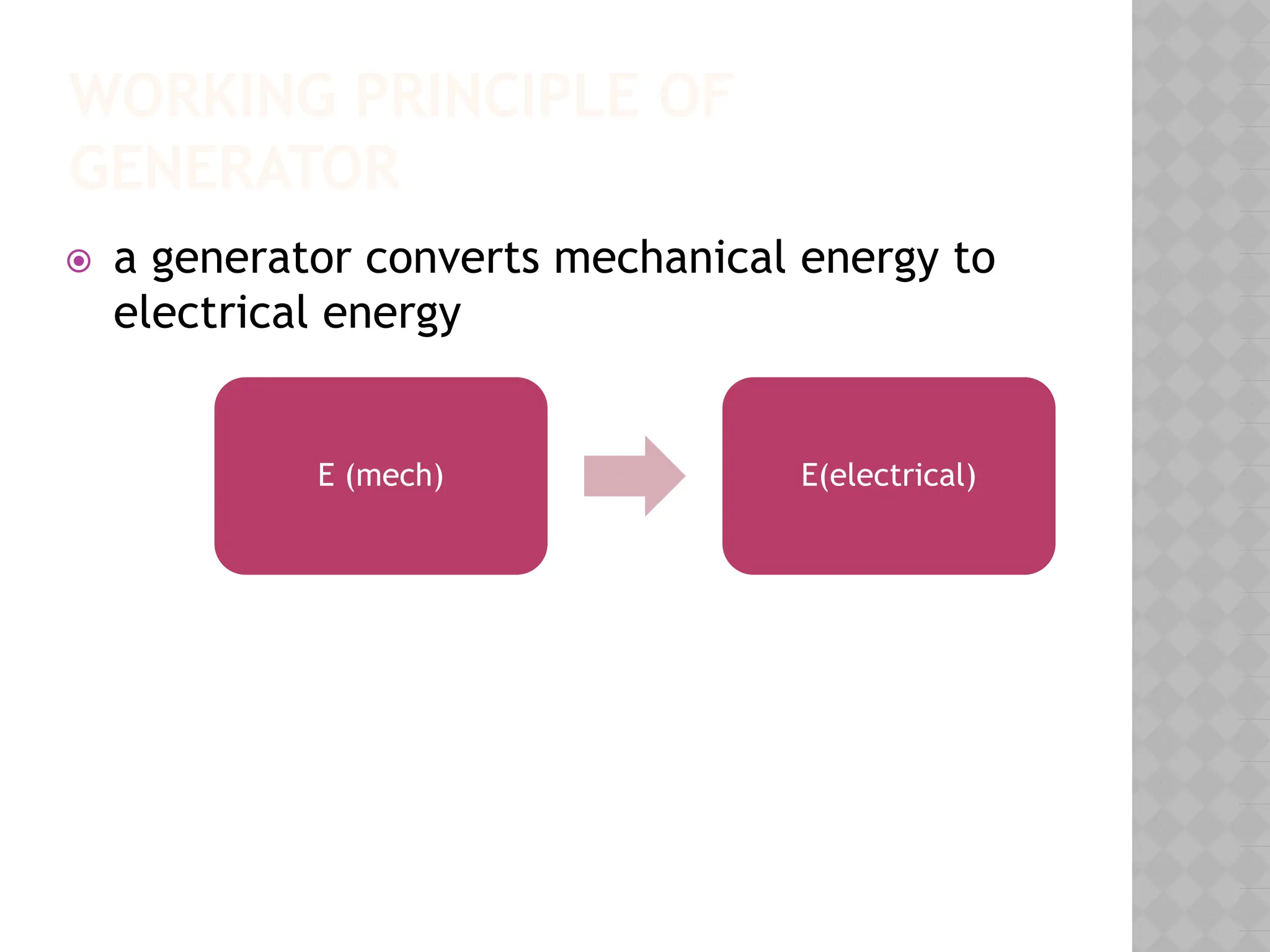
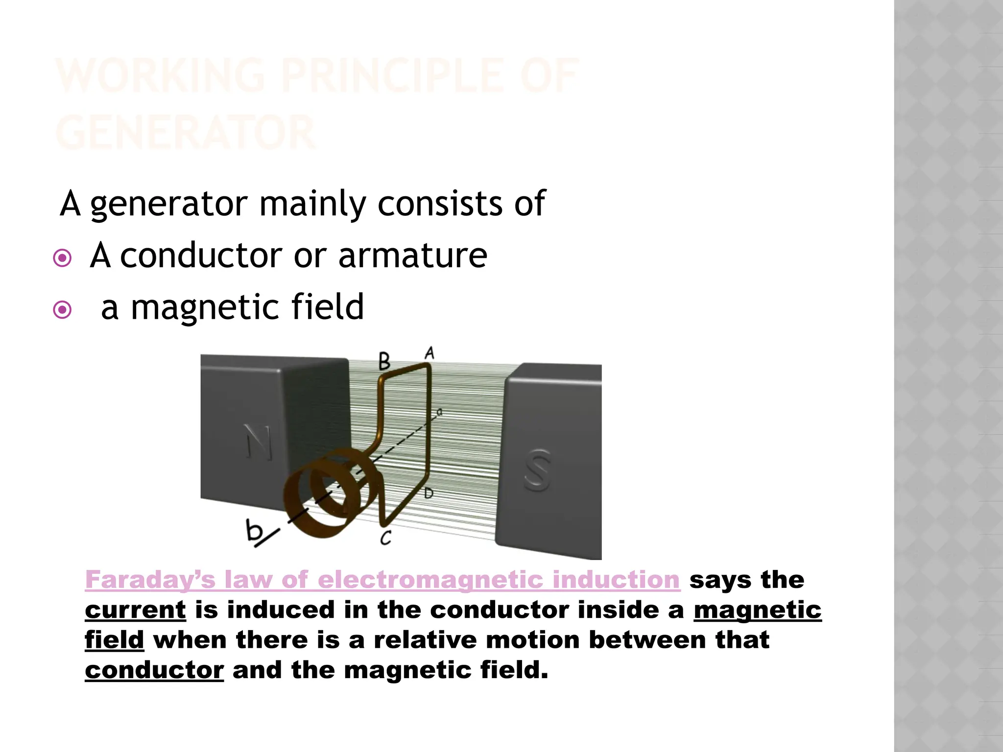
Agenerator mainly consists of
⦿ A conductor or armature
⦿ a magnetic field
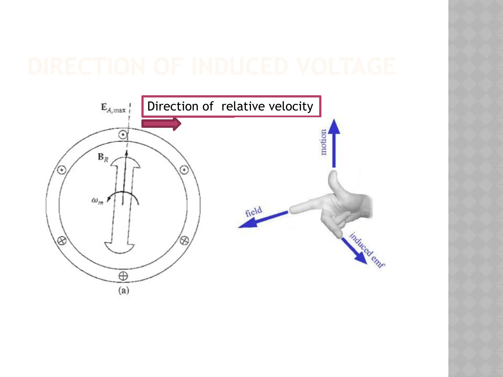
Faraday’s law of electromagnetic induction says the
current is induced in the conductor inside a magnetic
field when there is a relative motion between that
conductor and the magnetic field.
4.
BASIC CONSTRUCTION OF
SYNCHRONOUSGENERATOR
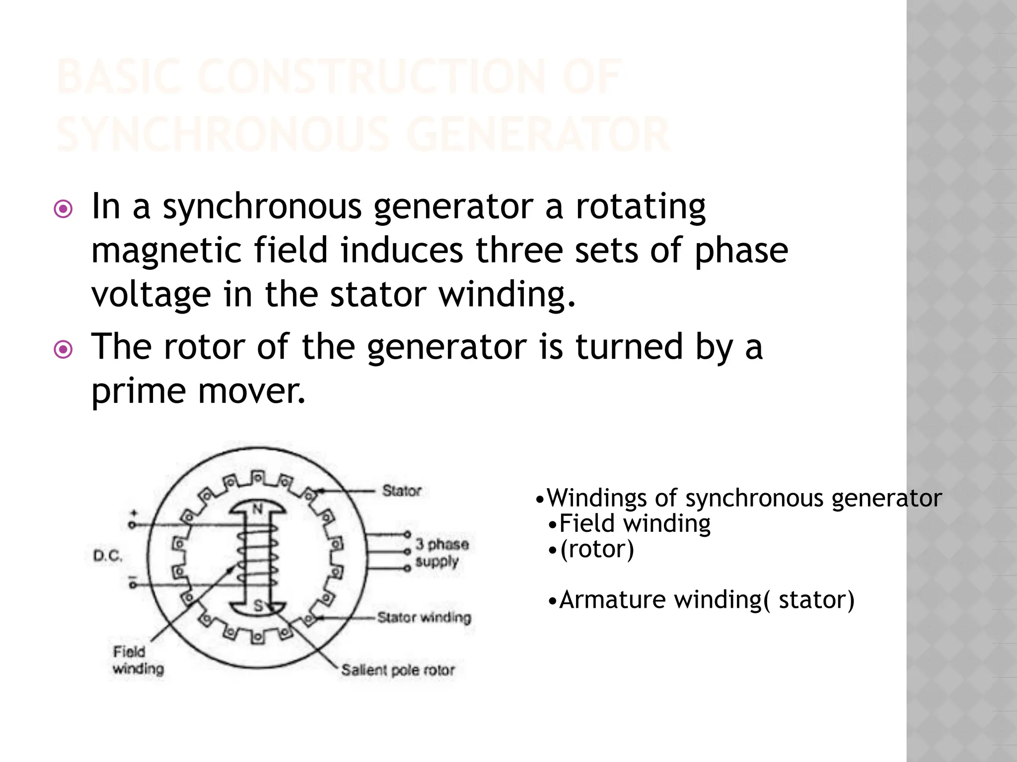
⦿ In a synchronous generator a rotating
magnetic field induces three sets of phase
voltage in the stator winding.
⦿ The rotor of the generator is turned by a
prime mover.
•Windings of synchronous generator
•Field winding
•(rotor)
•Armature winding( stator)
5.
ROTOR
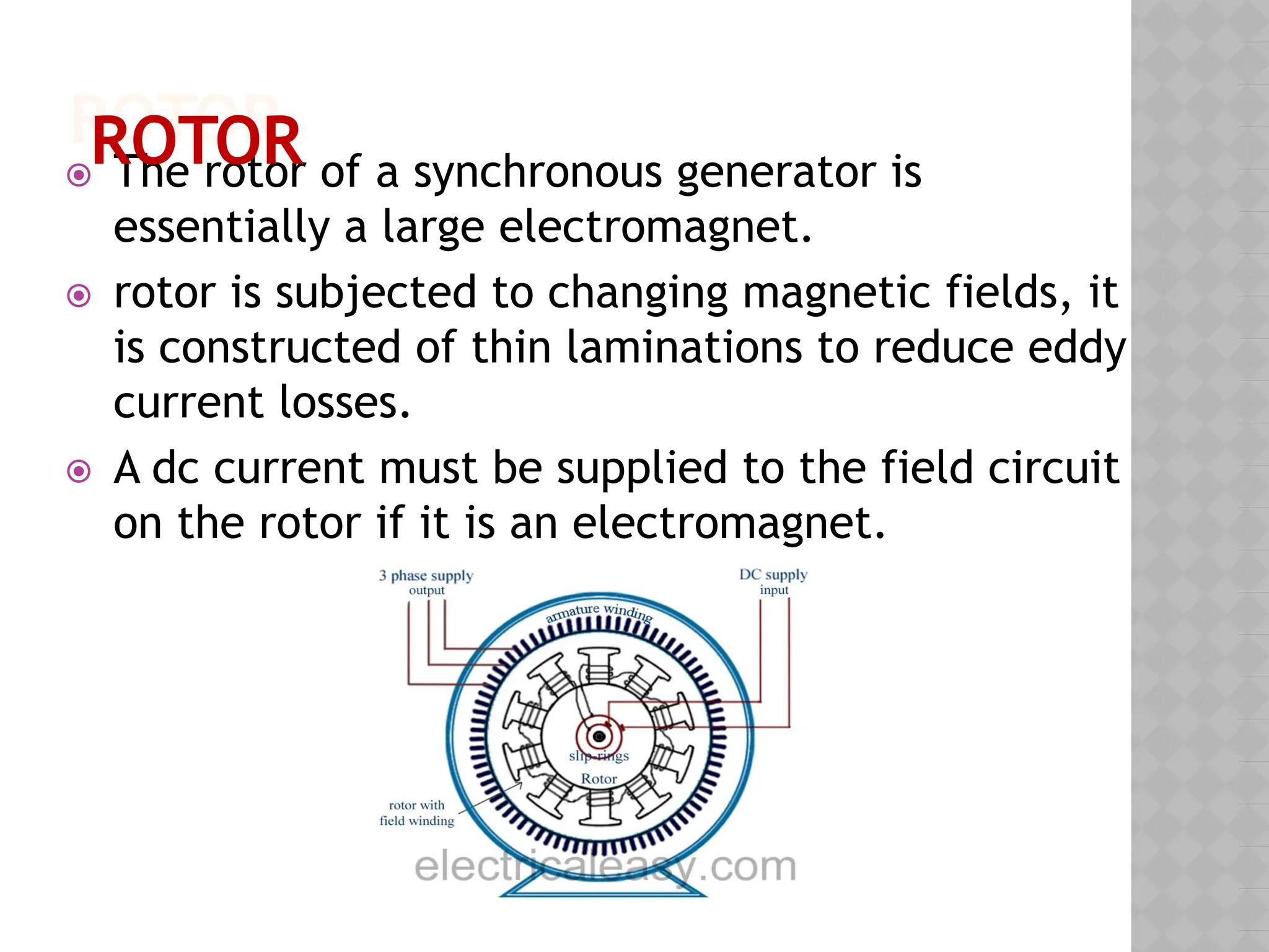
⦿ The rotorof a synchronous generator is
essentially a large electromagnet.
⦿ rotor is subjected to changing magnetic fields, it
is constructed of thin laminations to reduce eddy
current losses.
⦿ A dc current must be supplied to the field circuit
on the rotor if it is an electromagnet.
ROTOR
6.
ROTOR / FIELDWINDING
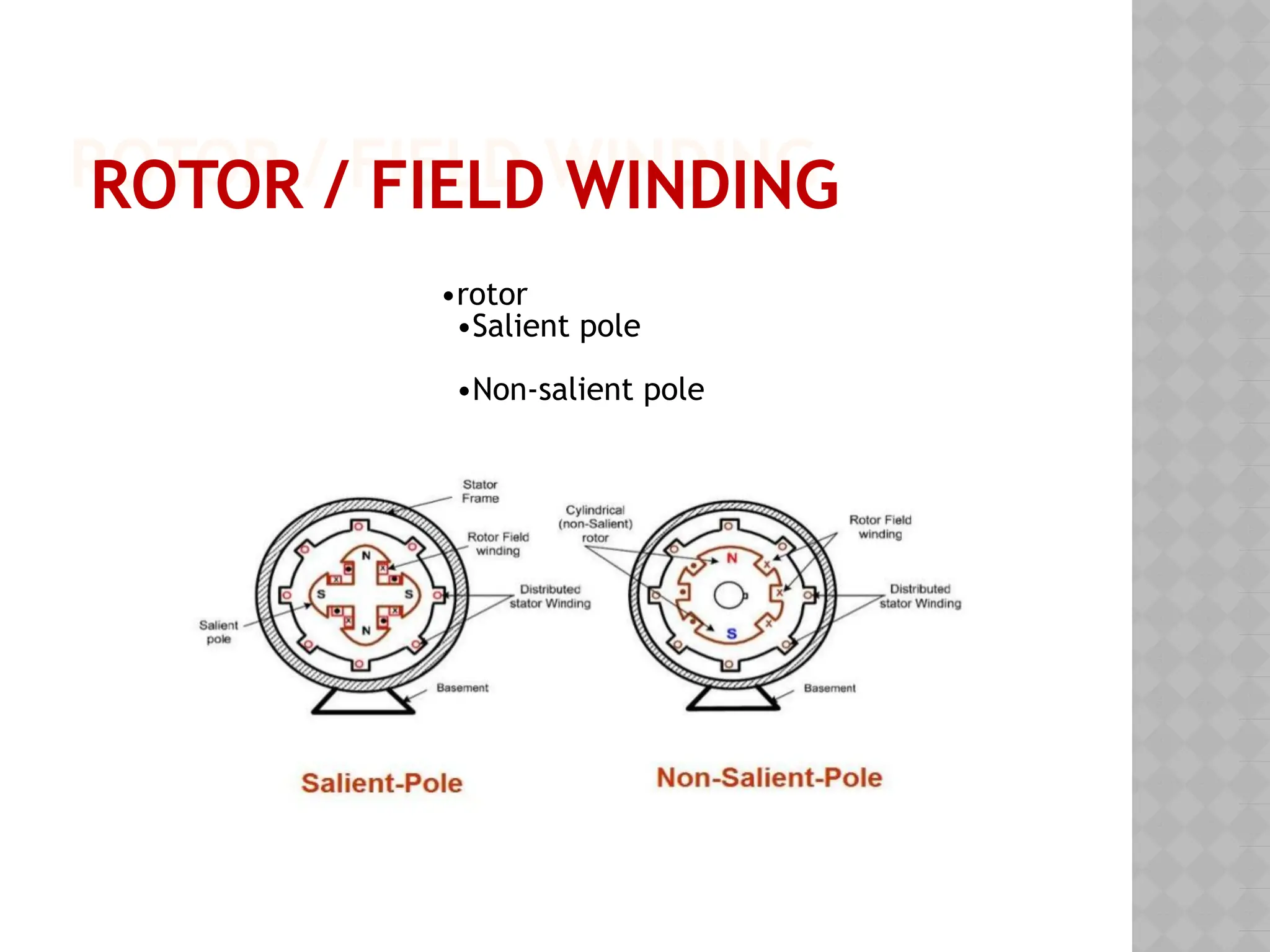
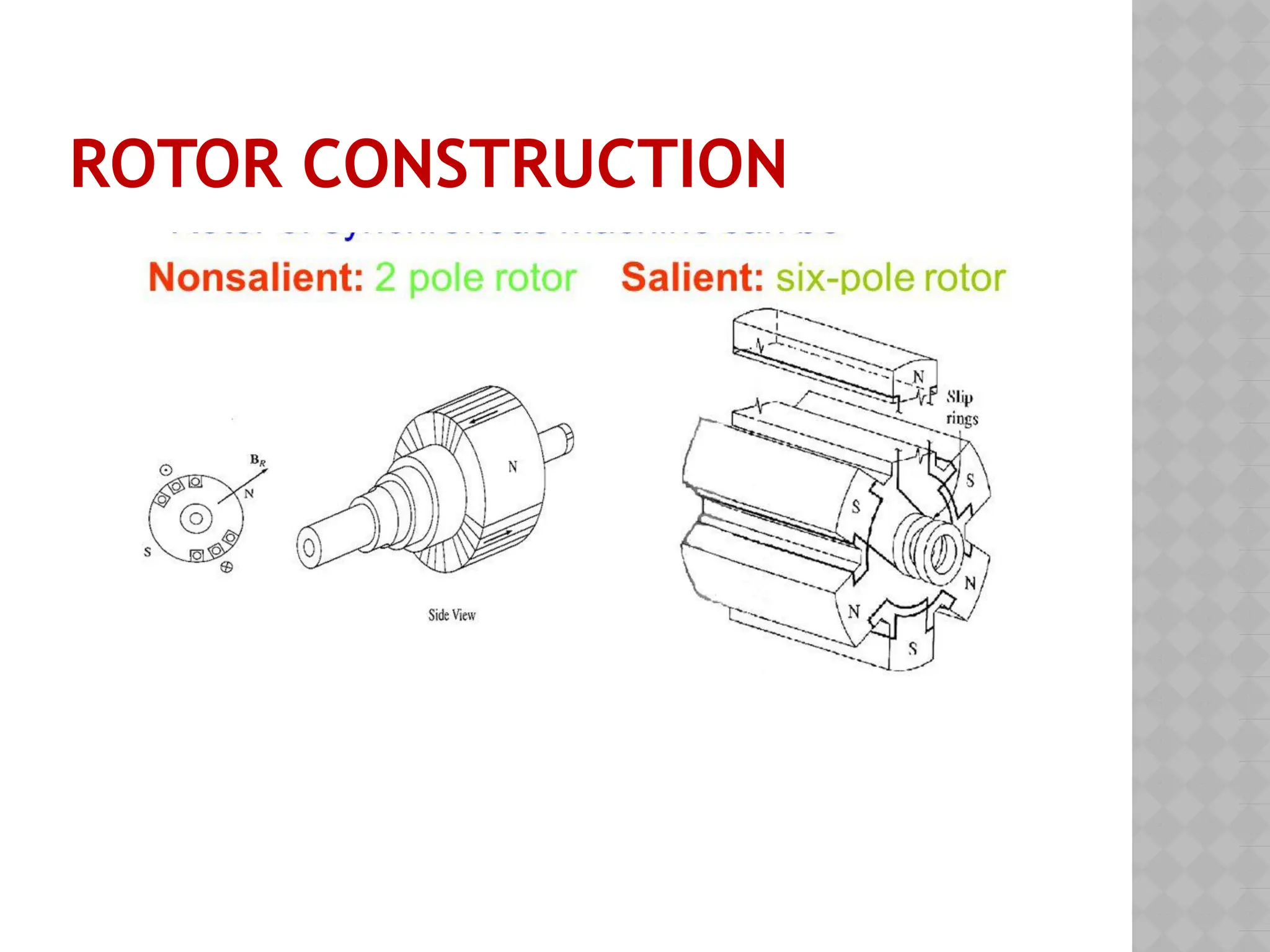
•rotor
•Salient pole
•Non-salient pole
ROTOR / FIELD WINDING
ROTOR /FIELD WINDING
Thereare two common approaches to
supplying this dc power:
⦿ Supply the dc power from an external dc
source to the rotor by means of slip rings and
brushes.
⦿ Supply the dc power from a special dc
power source mounted directly on the
shaft of the synchronous generator.
9.
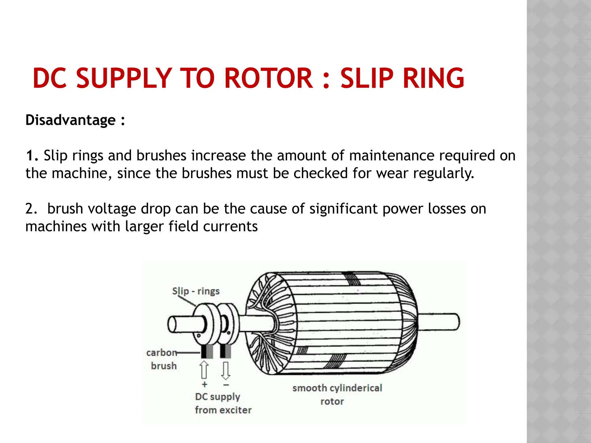
DC SUPPLY TOROTOR : SLIP RING
Disadvantage :
1. Slip rings and brushes increase the amount of maintenance required on
the machine, since the brushes must be checked for wear regularly.
2. brush voltage drop can be the cause of significant power losses on
machines with larger field currents
10.
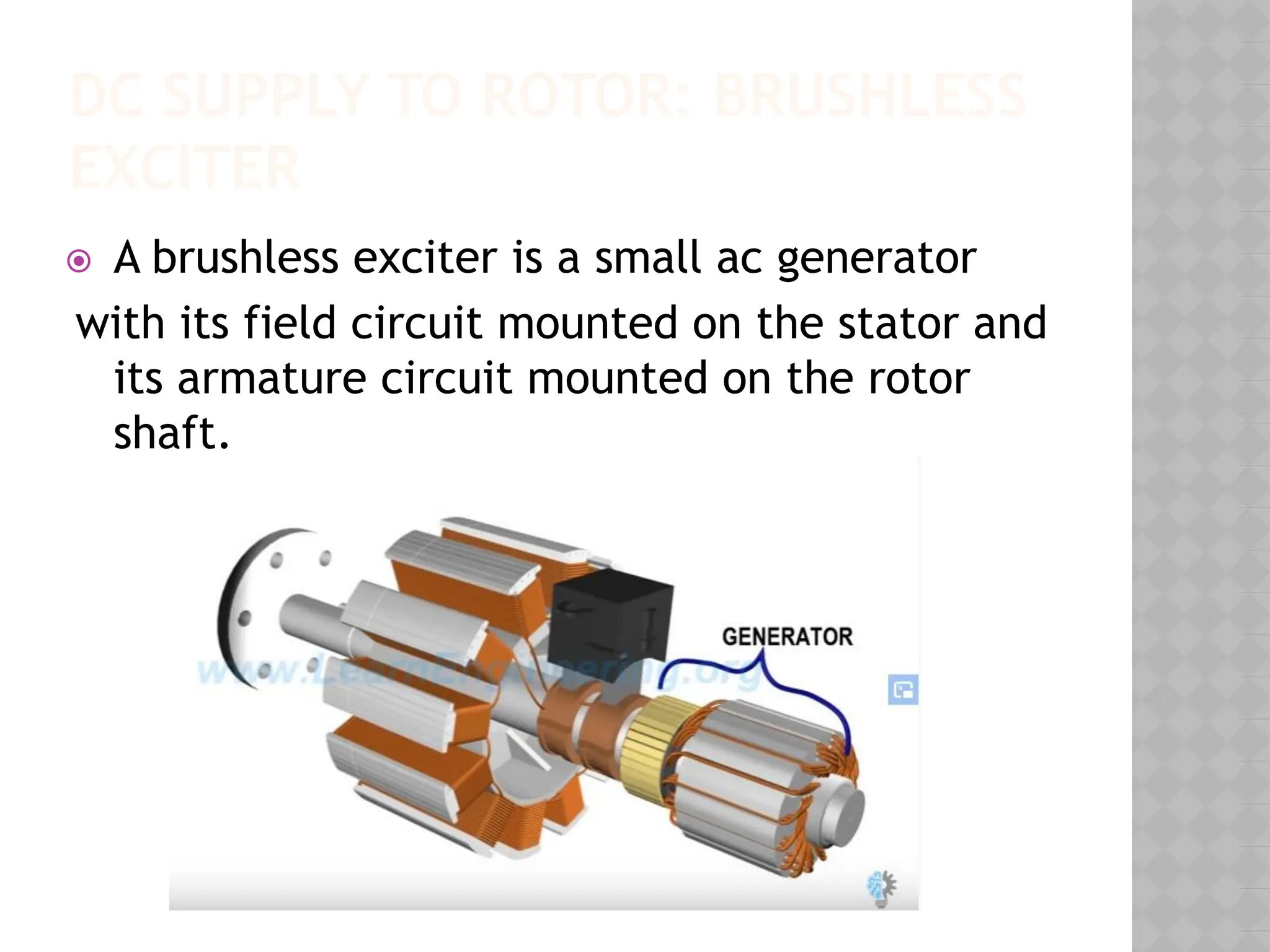
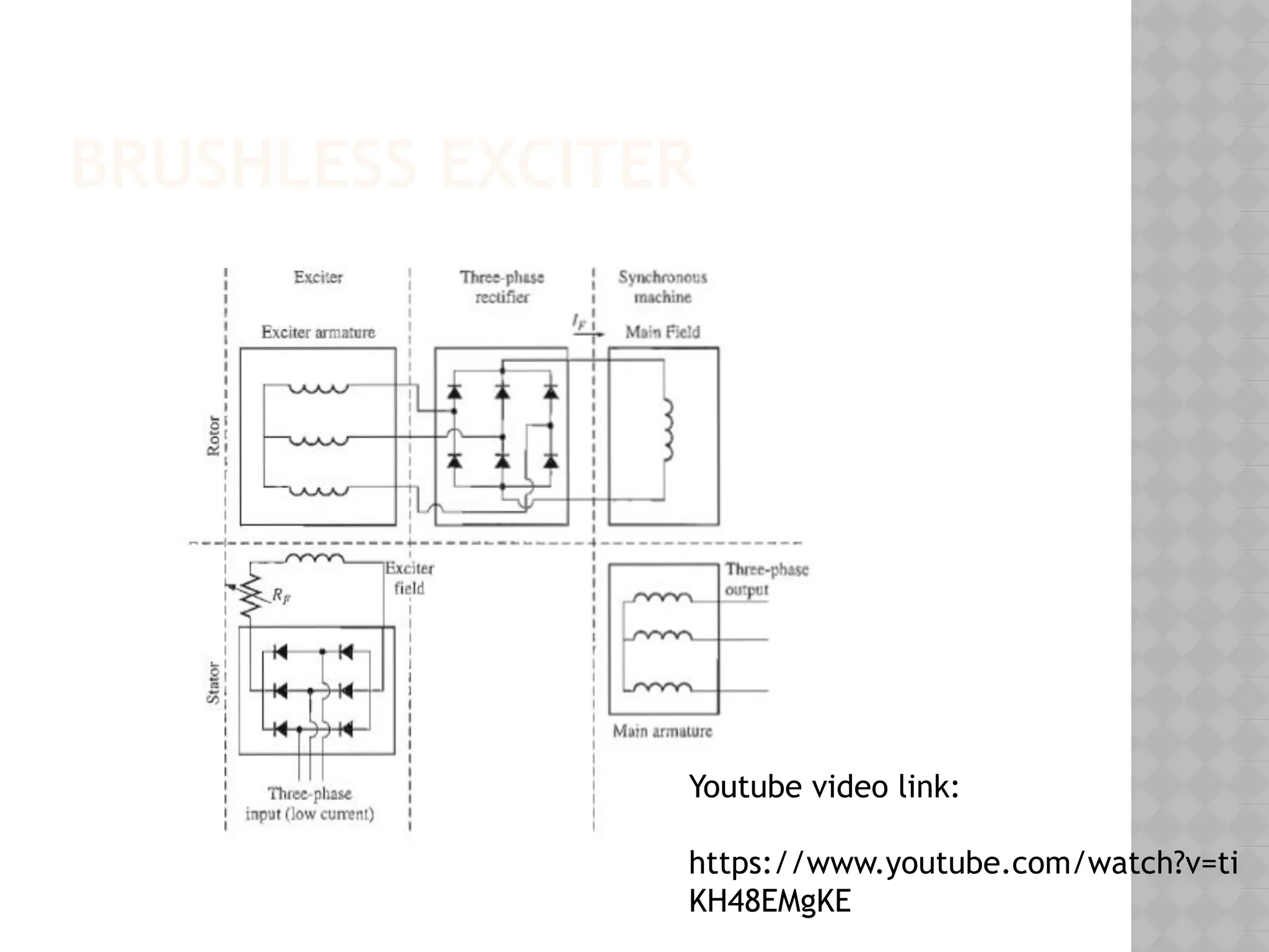
DC SUPPLY TOROTOR: BRUSHLESS
EXCITER
⦿ A brushless exciter is a small ac generator
with its field circuit mounted on the stator and
its armature circuit mounted on the rotor
shaft.
SPEED OF ROTATIONOF
SYNCHRONOUS GENERATOR
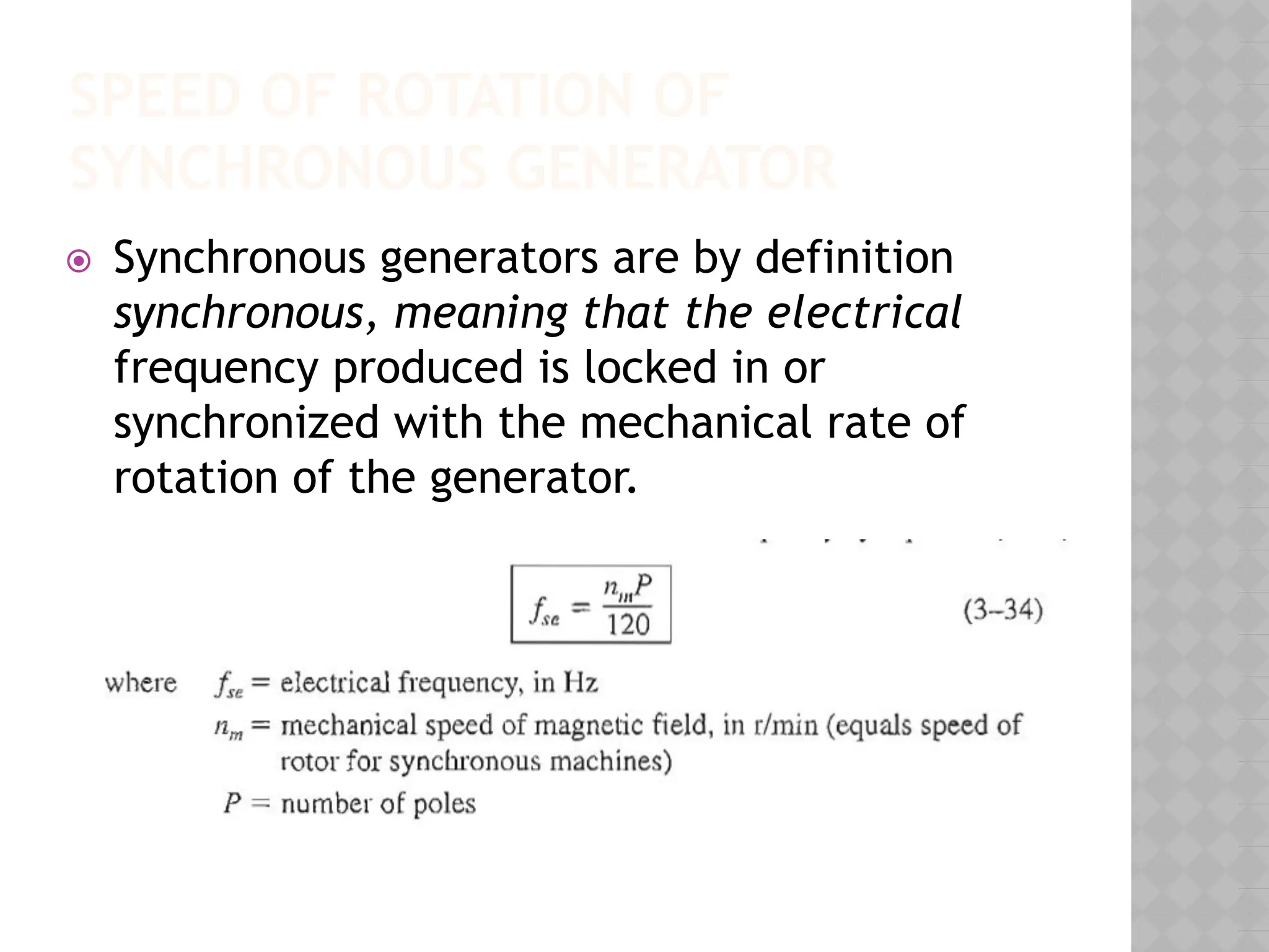
⦿ Synchronous generators are by definition
synchronous, meaning that the electrical
frequency produced is locked in or
synchronized with the mechanical rate of
rotation of the generator.
13.
INTERNAL GENERATED VOLTAGE/
INDUCEDVOLTAGE
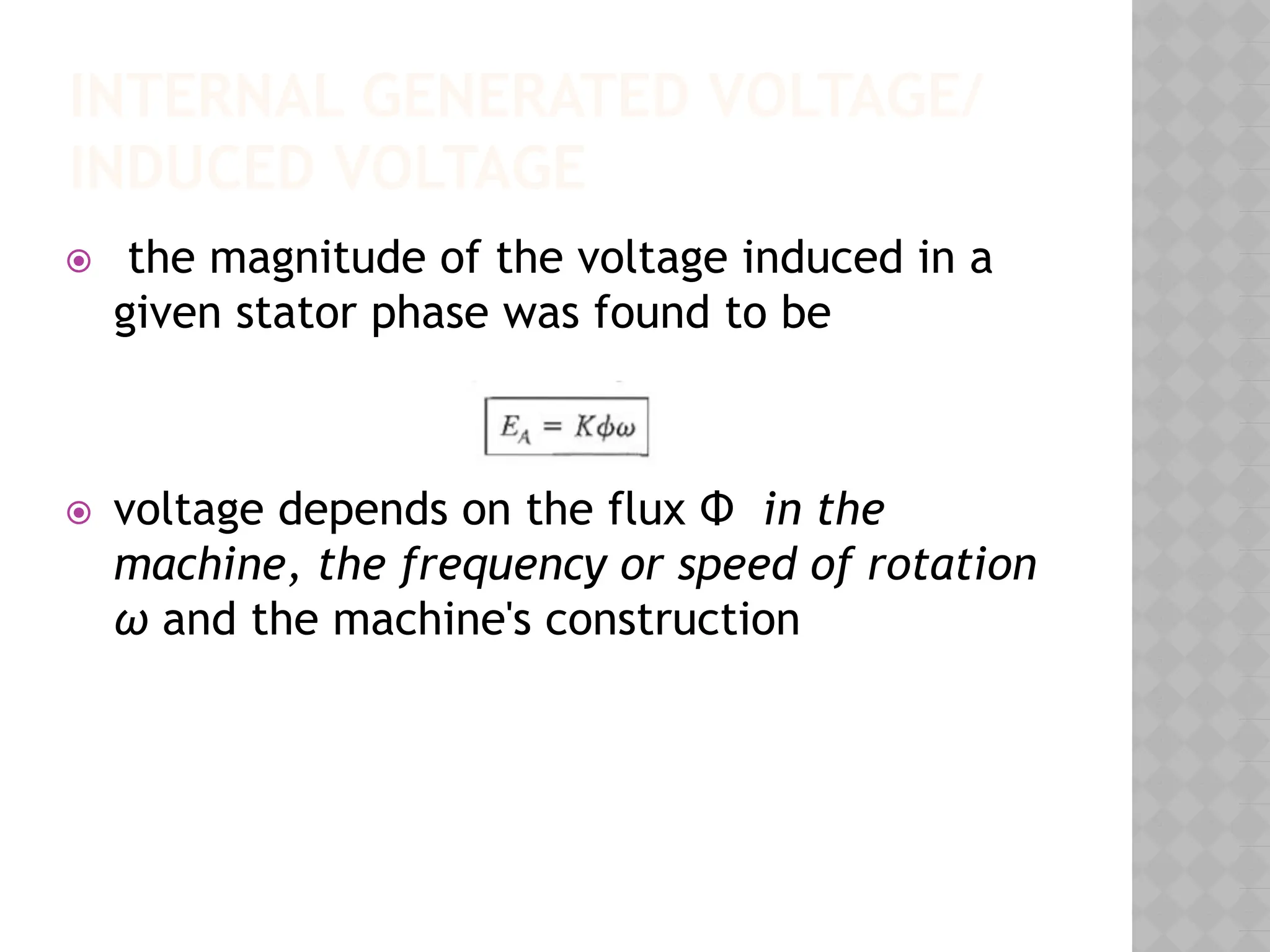
⦿ the magnitude of the voltage induced in a
given stator phase was found to be
⦿ voltage depends on the flux Φ in the
machine, the frequency or speed of rotation
ω and the machine's construction
14.
INTERNAL GENERATED VOLTAGE
ANDTERMINAL VOLTAGE
⦿ voltage EA is not usually the voltage that appears at
the terminals of the generator VΦ
⦿ EA≠ VΦ
Why?
There are a number of factors that cause the
difference between EA and VΦ :
⦿ The distortion of the air-gap magnetic field by the
current flowing in the stator, called armature
reaction.
⦿ The self-inductance of the armature coils.
⦿ The resistance of the armature coils.
⦿ The effect of salient-pole rotor shapes.
15.
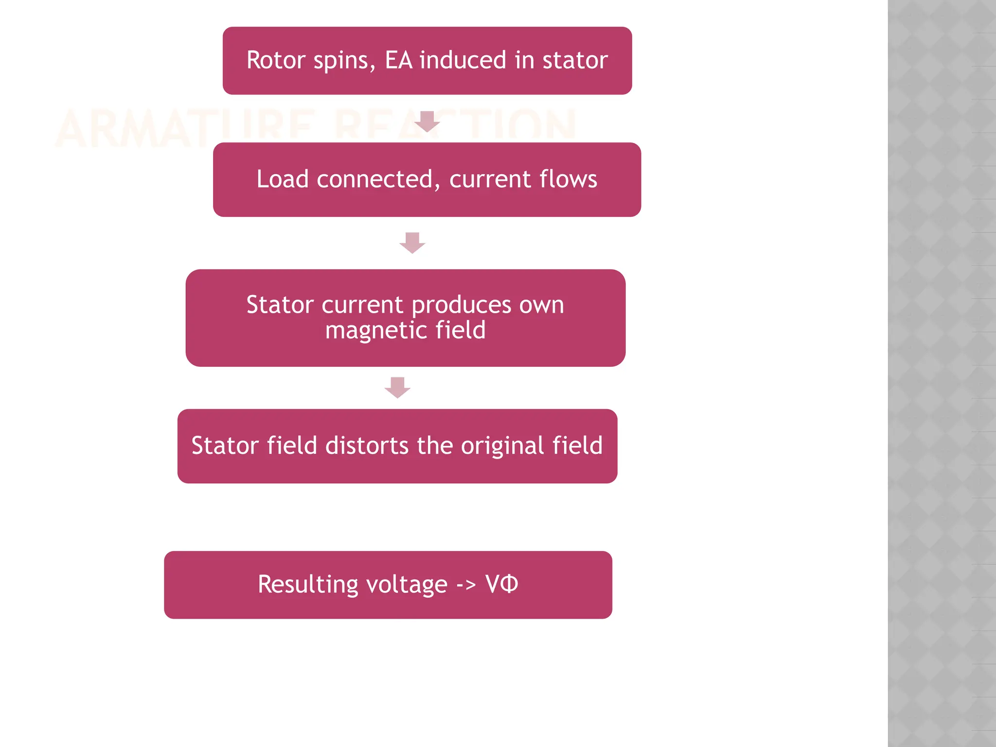
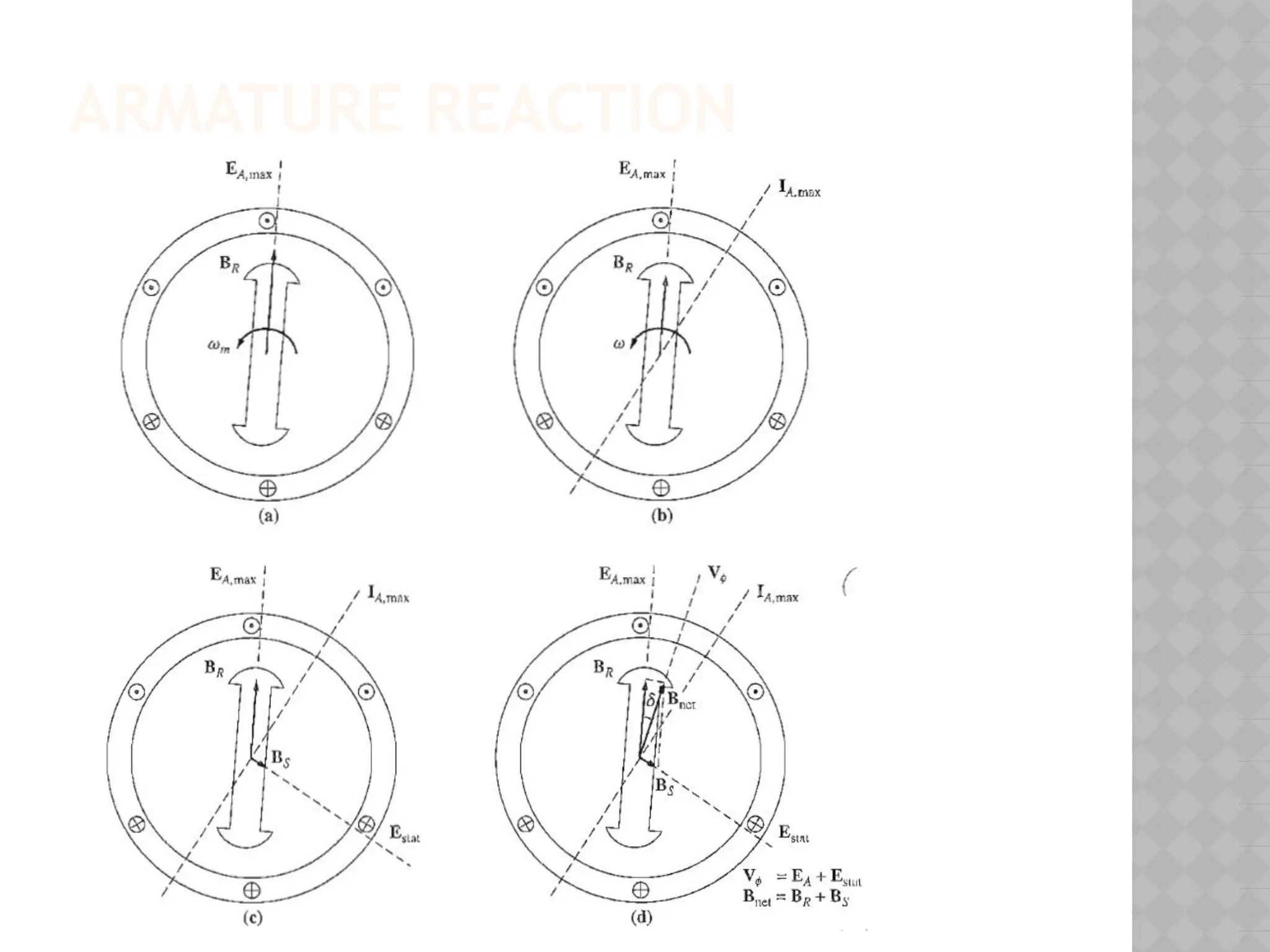
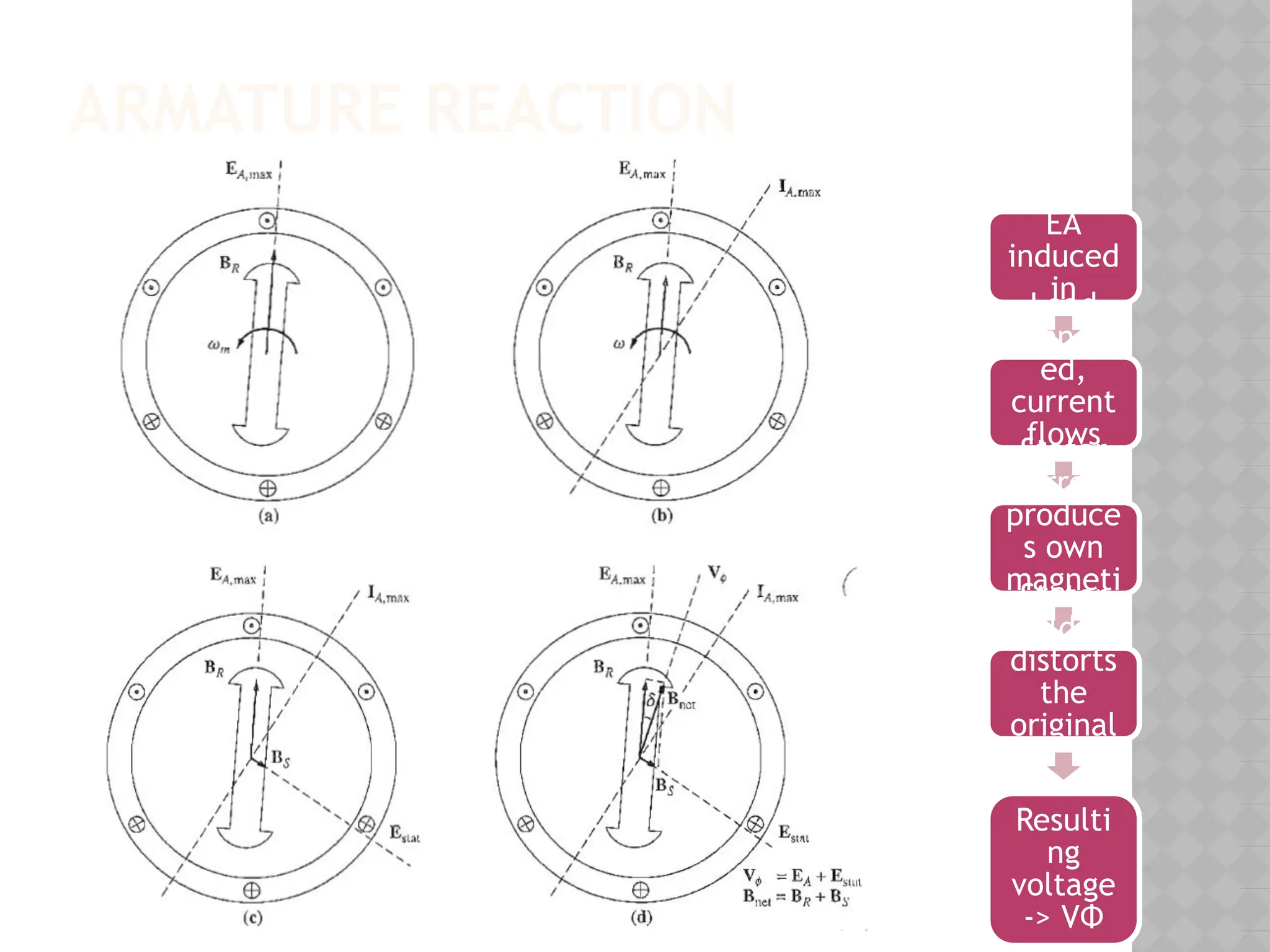
ARMATURE REACTION
Rotor spins,EA induced in stator
Load connected, current flows
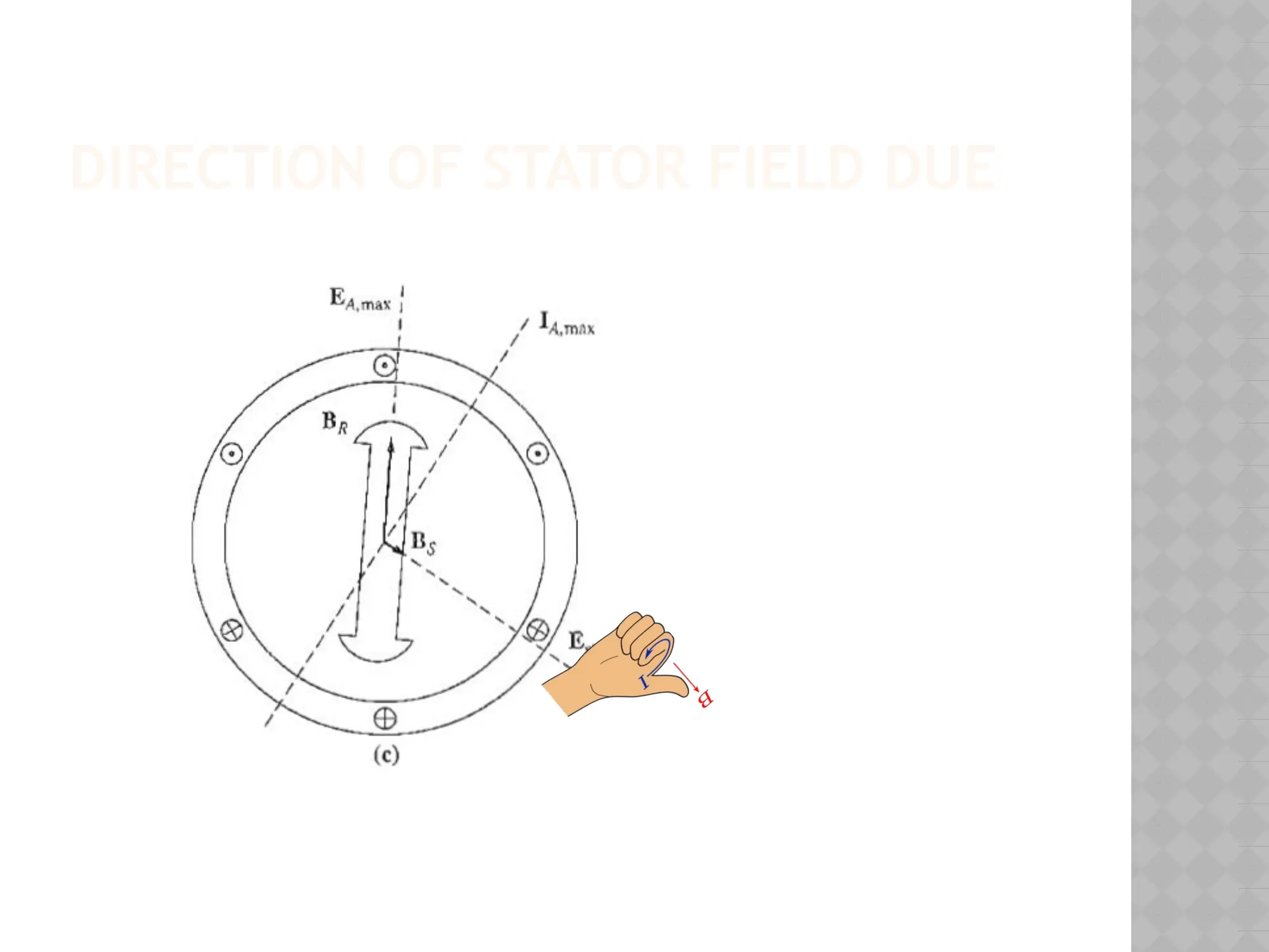
Stator current produces own
magnetic field
Stator field distorts the original field
Resulting voltage -> VΦ
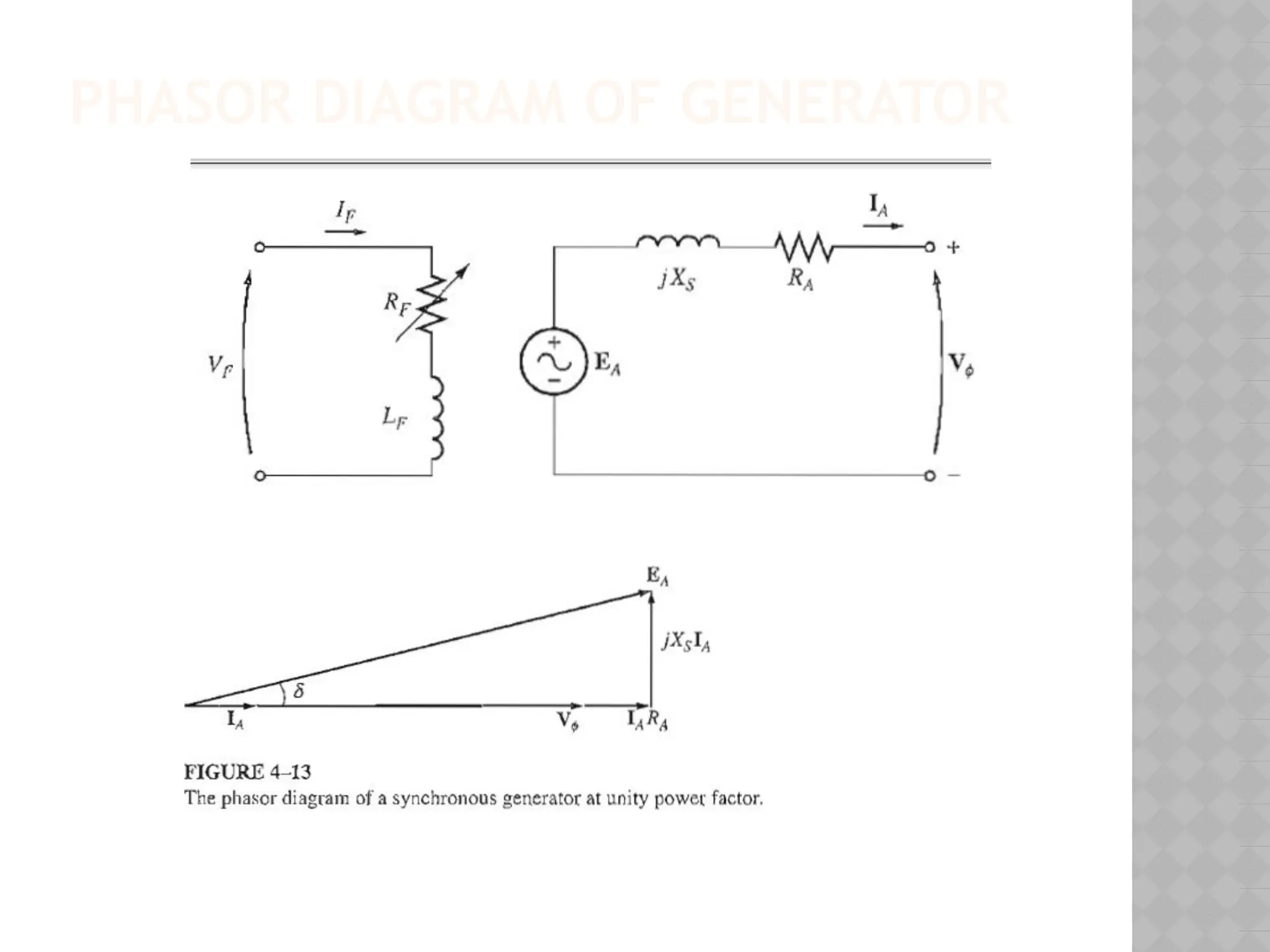
EQUIVALENT CIRCUIT OF
GENERATOR
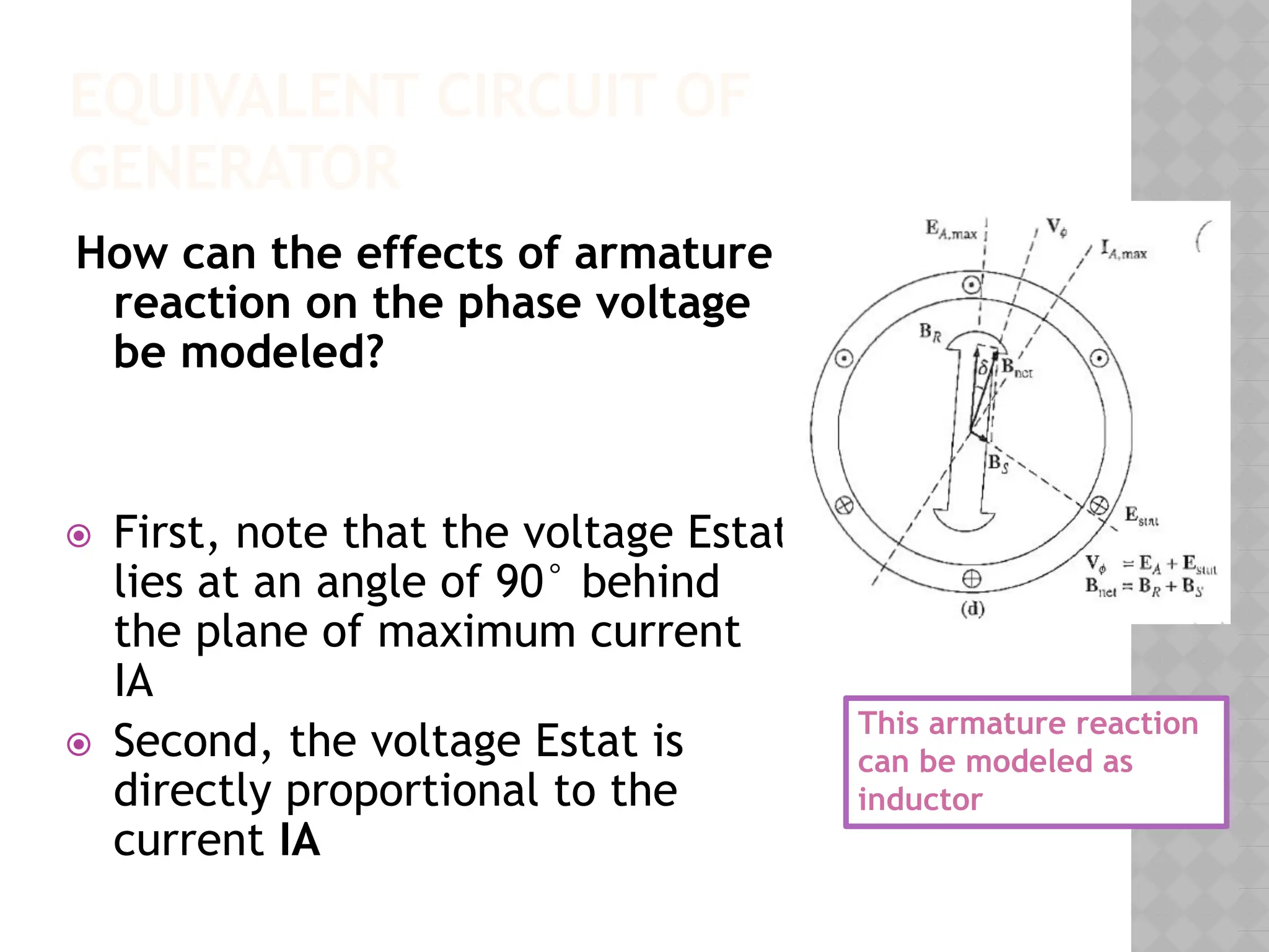
Howcan the effects of armature
reaction on the phase voltage
be modeled?
⦿ First, note that the voltage Estat
lies at an angle of 90° behind
the plane of maximum current
IA
⦿ Second, the voltage Estat is
directly proportional to the
current IA
This armature reaction
can be modeled as
inductor
EQUIVALENT CIRCUIT OF
GENERATOR
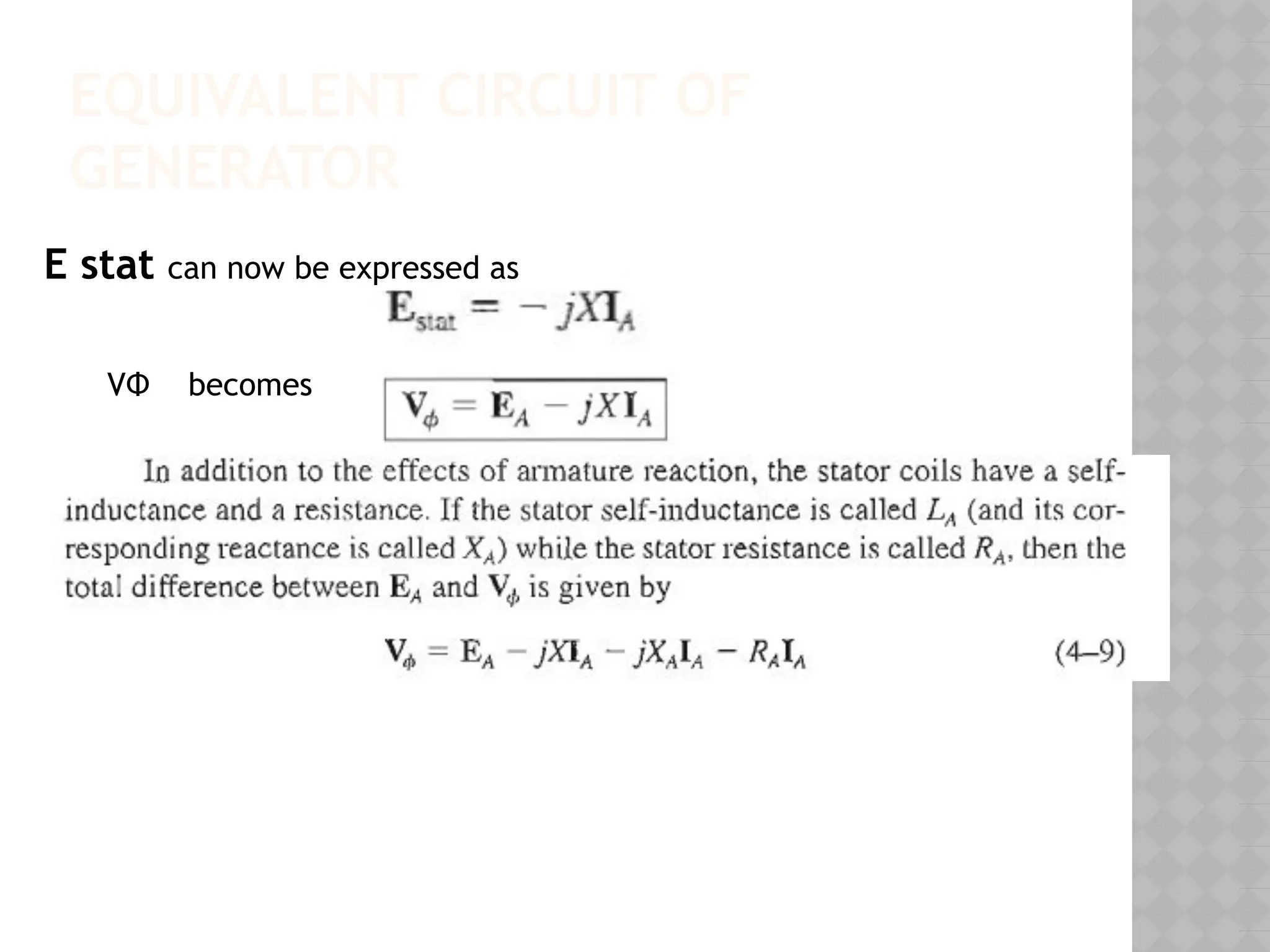
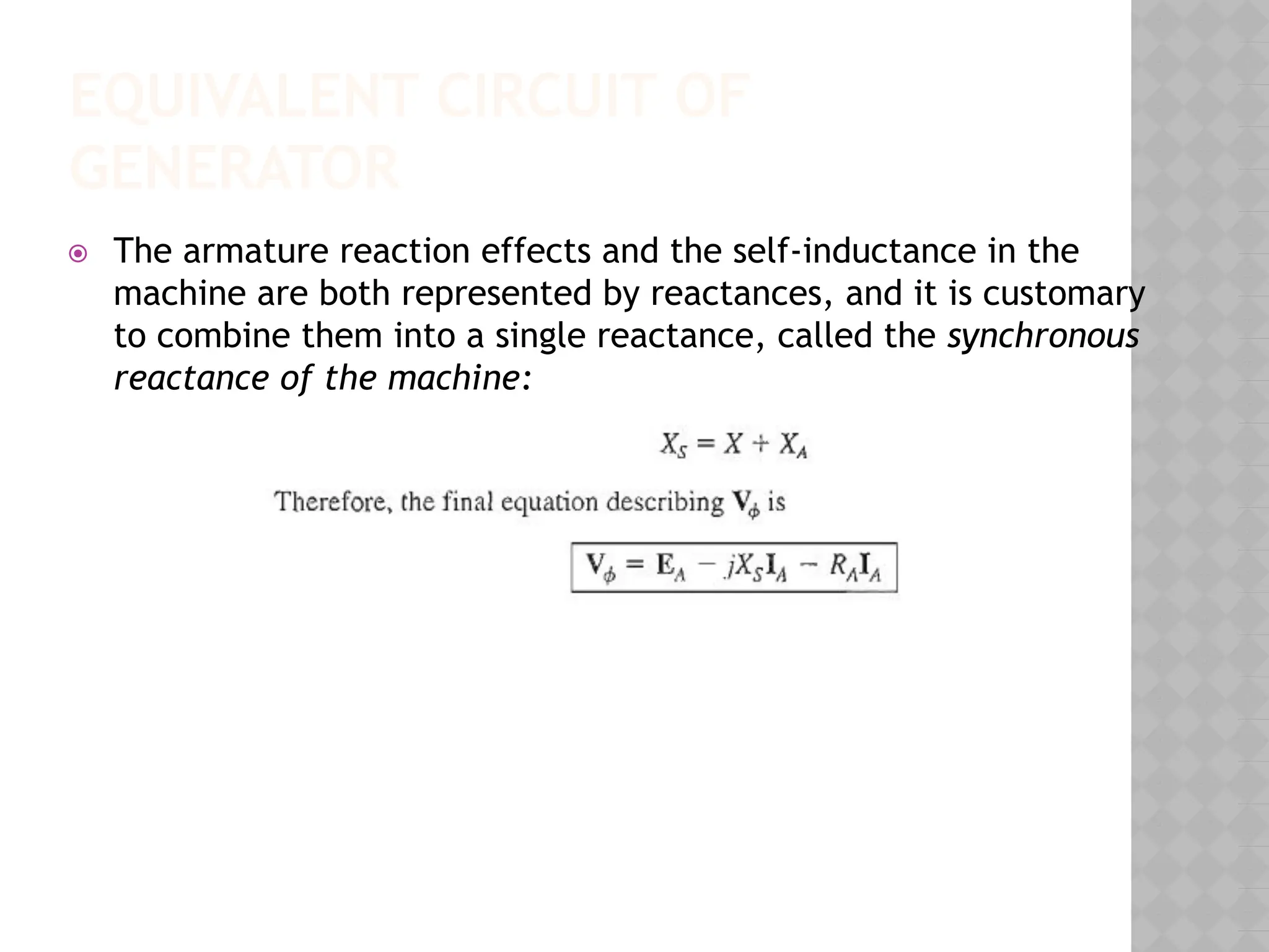
⦿The armature reaction effects and the self-inductance in the
machine are both represented by reactances, and it is customary
to combine them into a single reactance, called the synchronous
reactance of the machine:
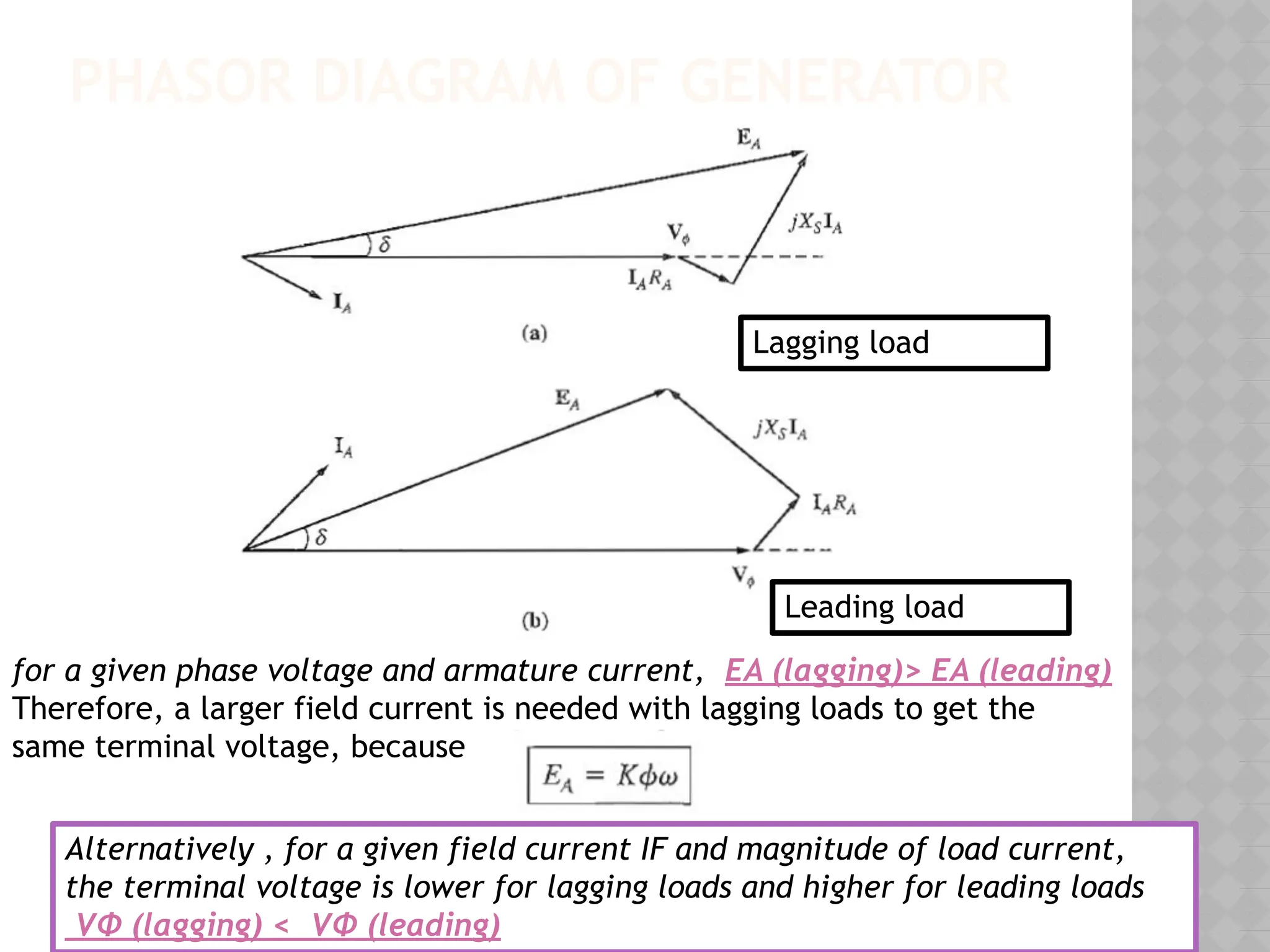
PHASOR DIAGRAM OFGENERATOR
Lagging load
Leading load
for a given phase voltage and armature current, EA (lagging)> EA (leading)
Therefore, a larger field current is needed with lagging loads to get the
same terminal voltage, because
Alternatively , for a given field current IF and magnitude of load current,
the terminal voltage is lower for lagging loads and higher for leading loads
VΦ (lagging) < VΦ (leading)
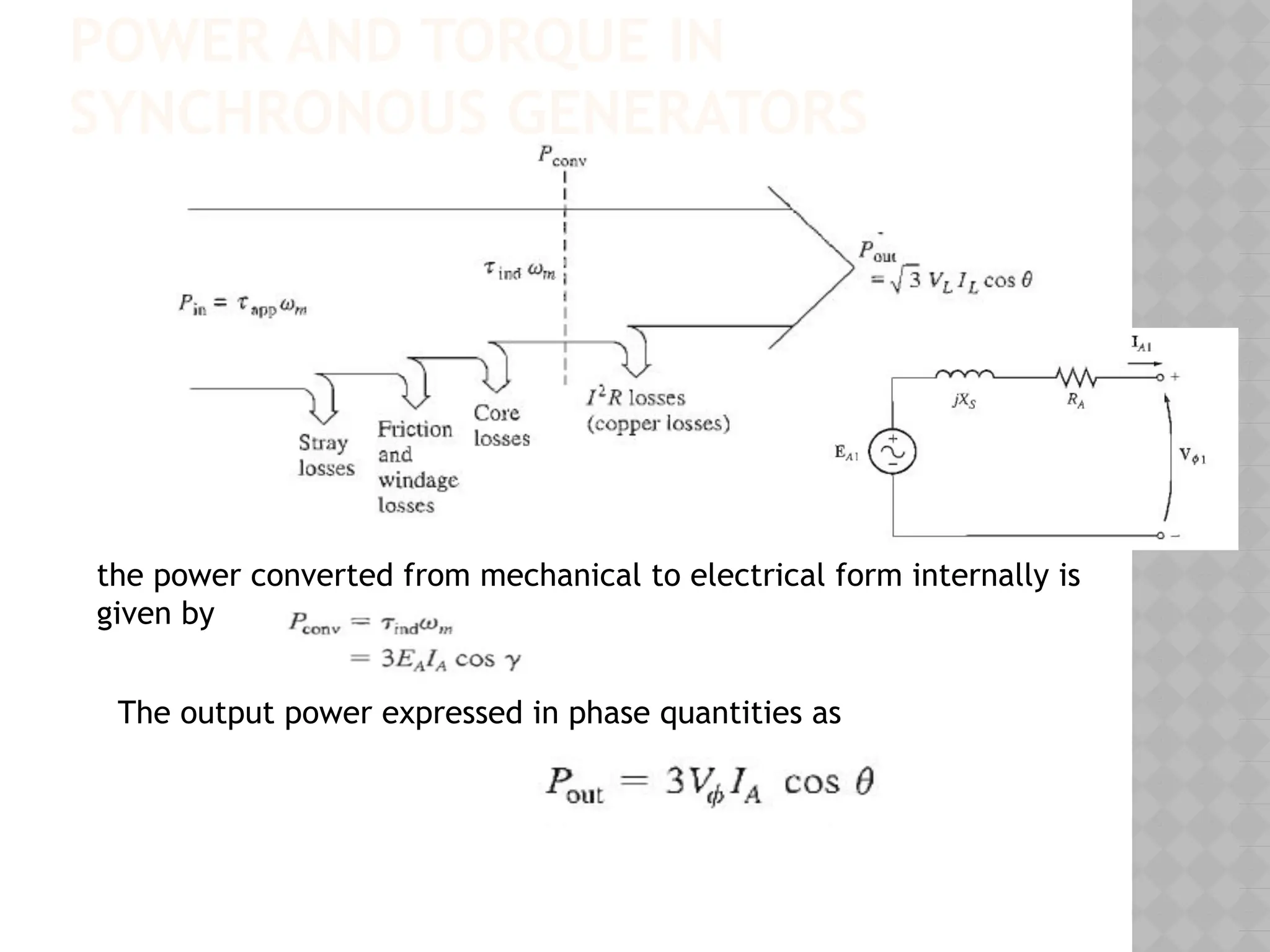
POWER AND TORQUEIN
SYNCHRONOUS GENERATORS
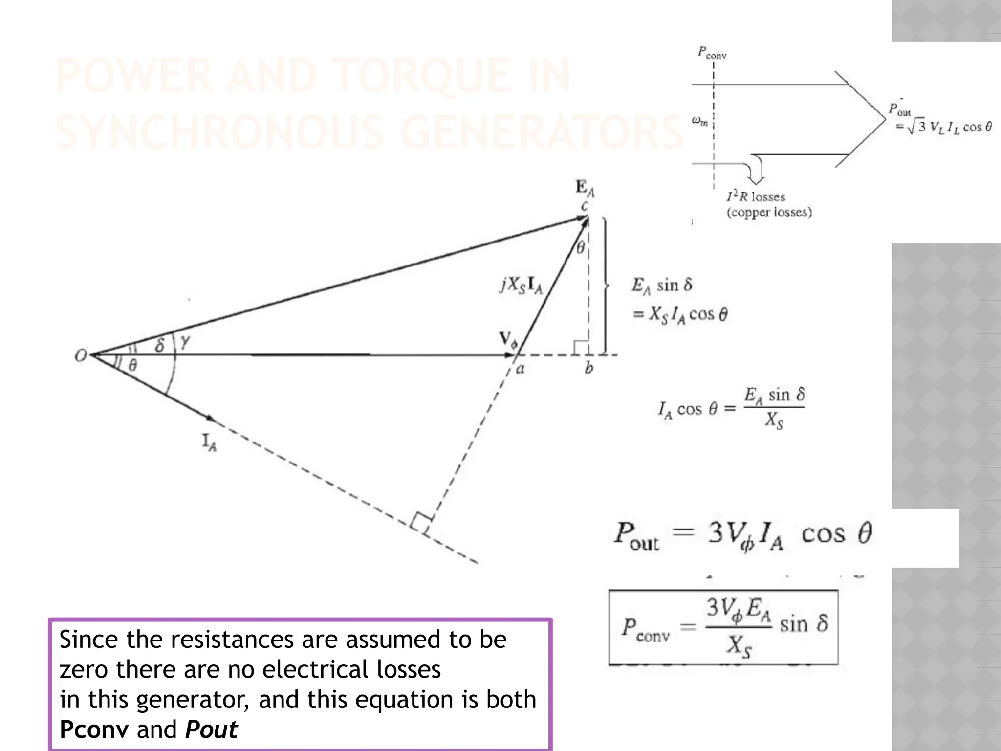
the power converted from mechanical to electrical form internally is
given by
The output power expressed in phase quantities as
29.
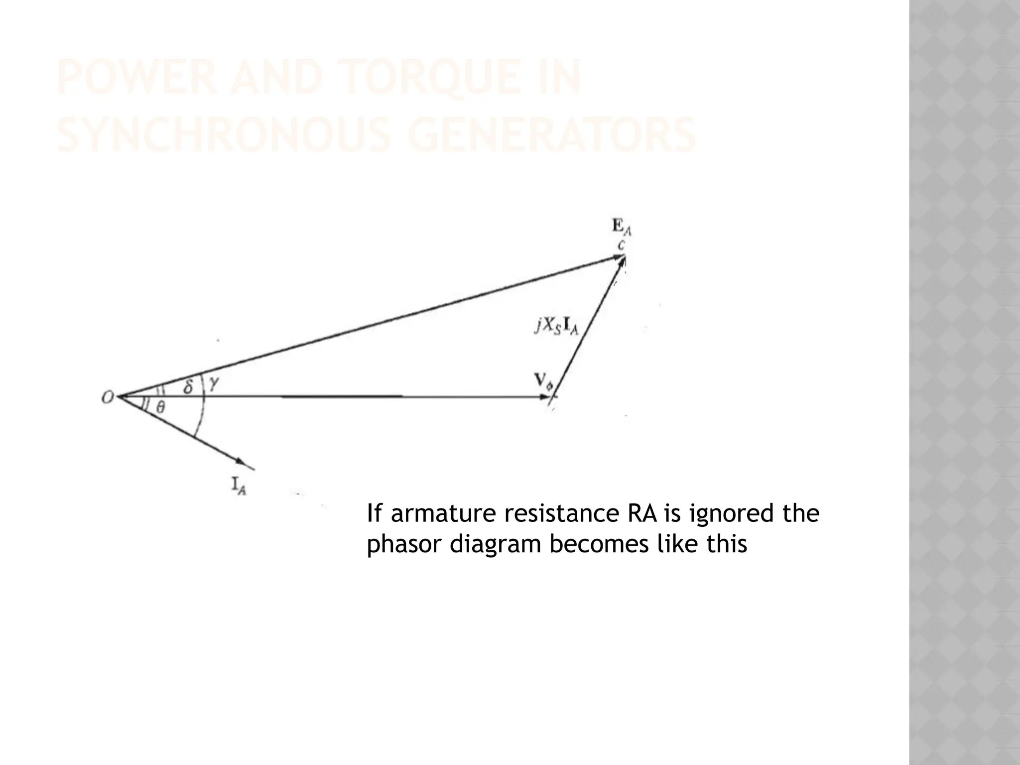
POWER AND TORQUEIN
SYNCHRONOUS GENERATORS
If armature resistance RA is ignored the
phasor diagram becomes like this
30.
POWER AND TORQUEIN
SYNCHRONOUS GENERATORS
Since the resistances are assumed to be
zero there are no electrical losses
in this generator, and this equation is both
Pconv and Pout
31.
POWER AND TORQUEIN
SYNCHRONOUS GENERATORS
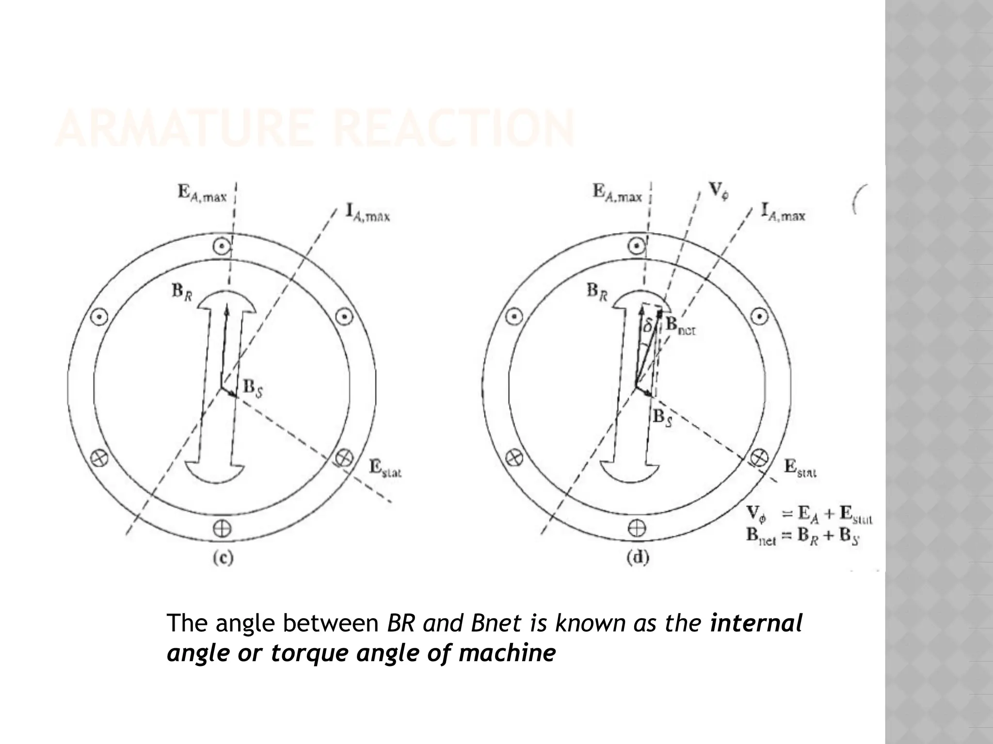
⦿ The angle δ is known as the internal angle or
torque angle of the machine.
⦿ Notice also that the maximum power that
the generator can supply occurs when = δ
=90 degrees & sin90=1
The maximum power indicated by this equation is calIed
the static stability limit of the generator
32.
TORQUE EQUATION
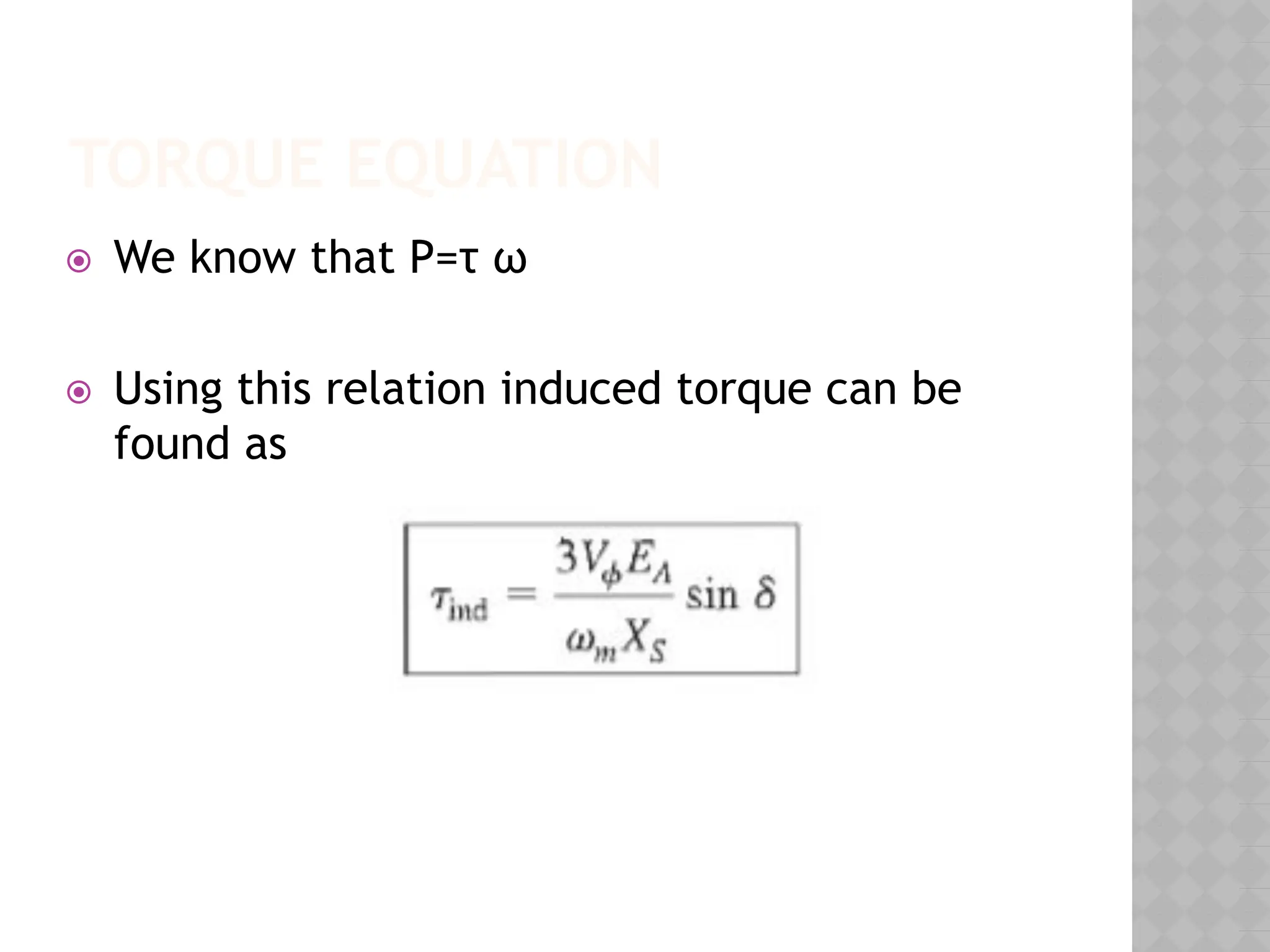
⦿ Weknow that P=τ ω
⦿ Using this relation induced torque can be
found as
33.
THE EFFECT OFLOAD CHANGES ON A
SYNCHRONOUS GENERATOR OPERATING
ALONE
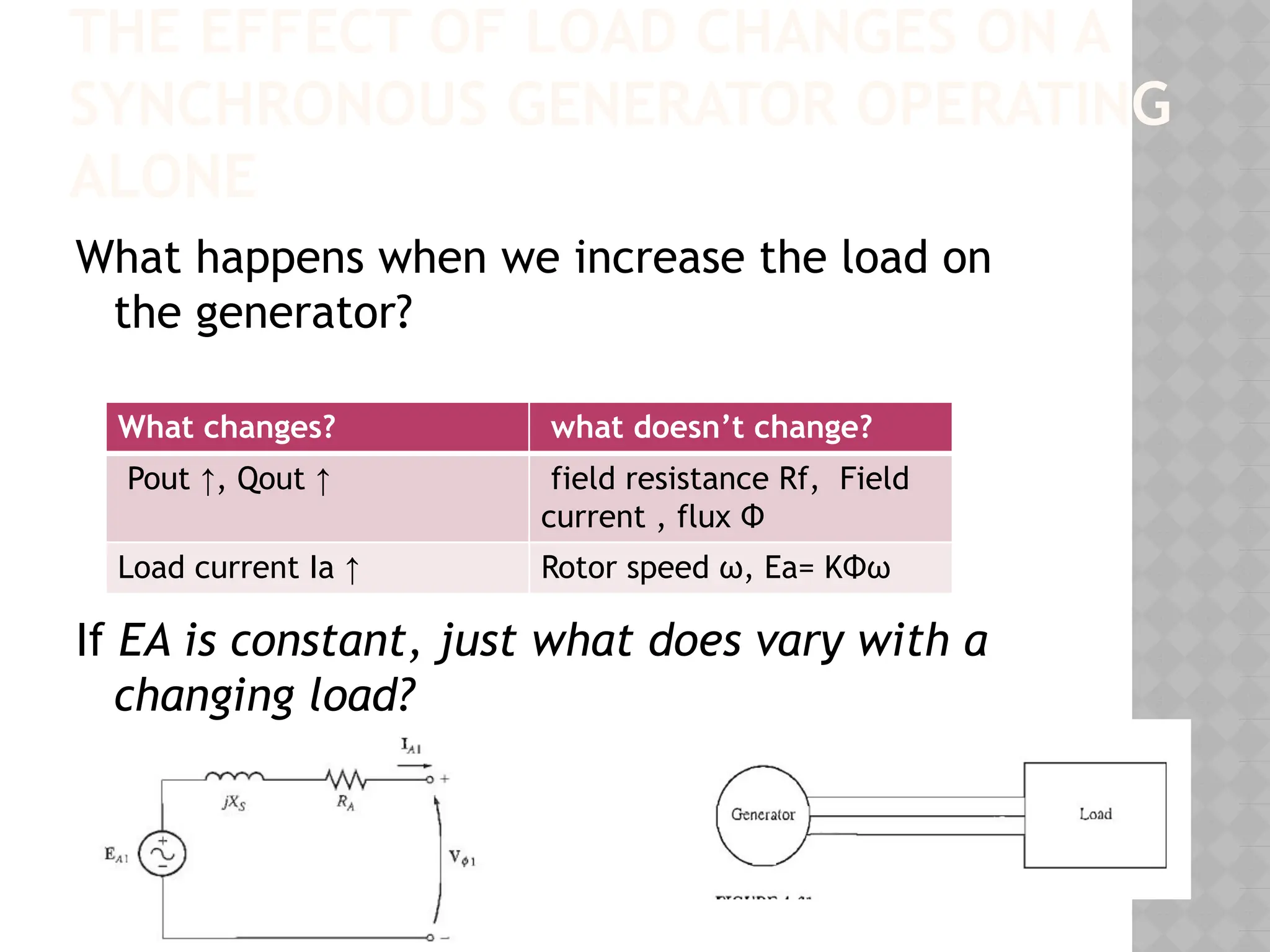
What happens when we increase the load on
the generator?
If EA is constant, just what does vary with a
changing load?
What changes? what doesn’t change?
Pout ↑, Qout ↑ field resistance Rf, Field
current , flux Φ
Load current Ia ↑ Rotor speed ω, Ea= KΦω
34.
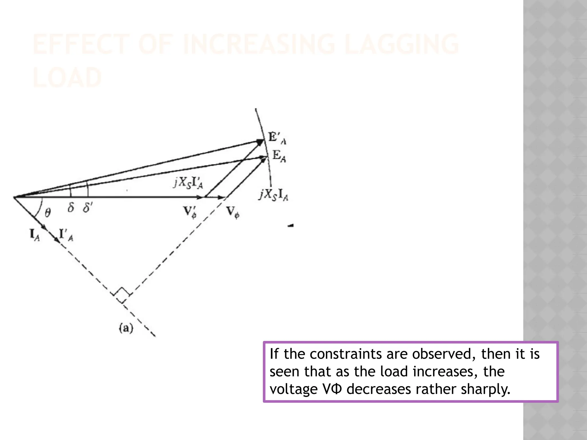
EFFECT OF INCREASINGLAGGING
LOAD
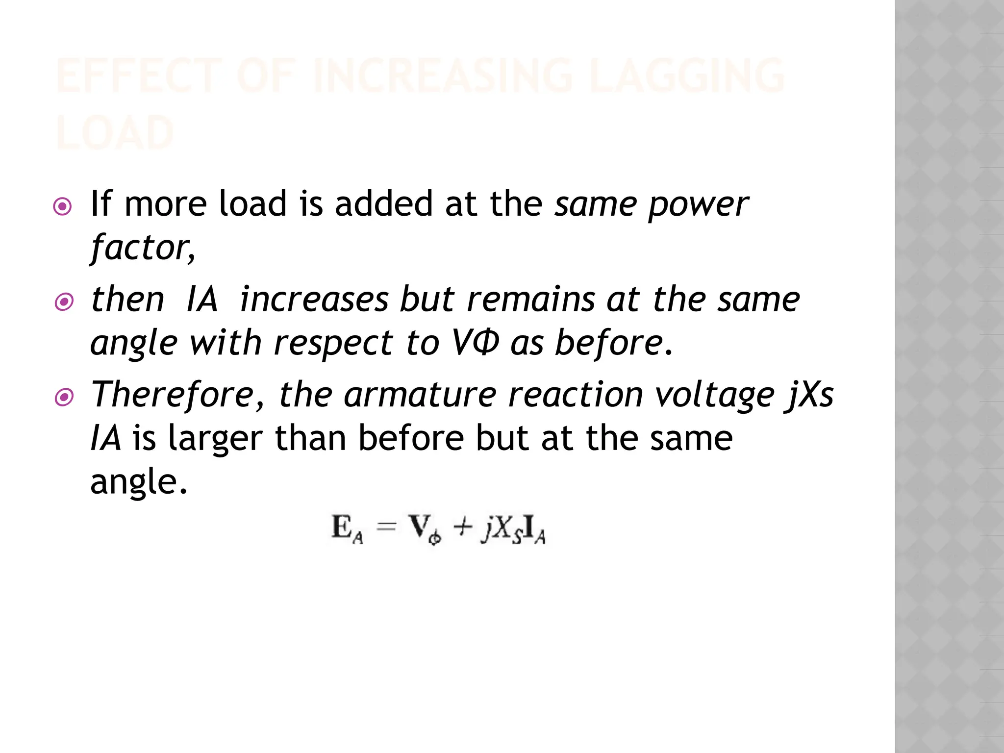
⦿ If more load is added at the same power
factor,
⦿ then IA increases but remains at the same
angle with respect to VΦ as before.
⦿ Therefore, the armature reaction voltage jXs
IA is larger than before but at the same
angle.
35.
EFFECT OF INCREASINGLAGGING
LOAD
If the constraints are observed, then it is
seen that as the load increases, the
voltage VΦ decreases rather sharply.
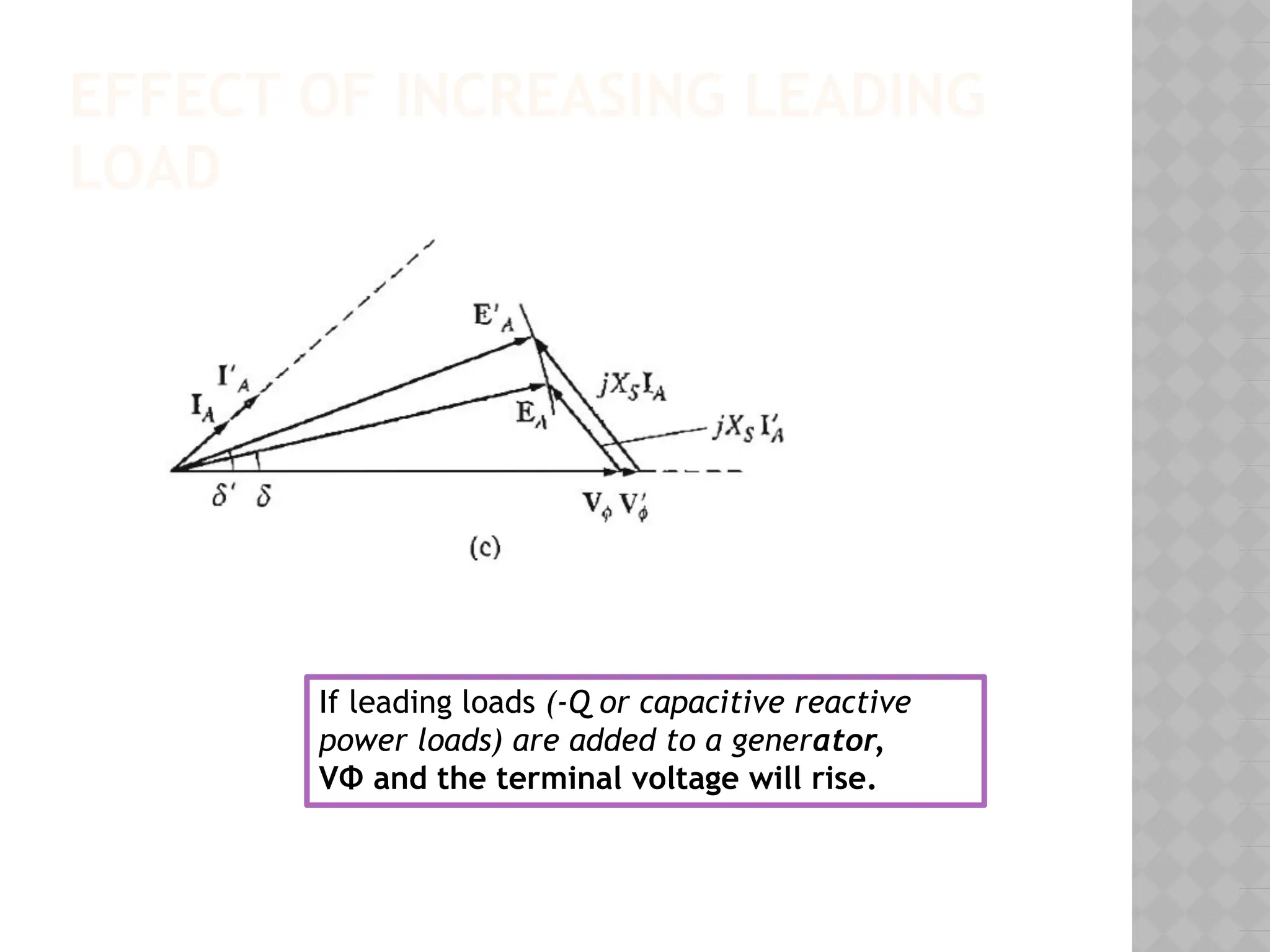
EFFECT OF INCREASINGLEADING
LOAD
If leading loads (-Q or capacitive reactive
power loads) are added to a generator,
VΦ and the terminal voltage will rise.
38.
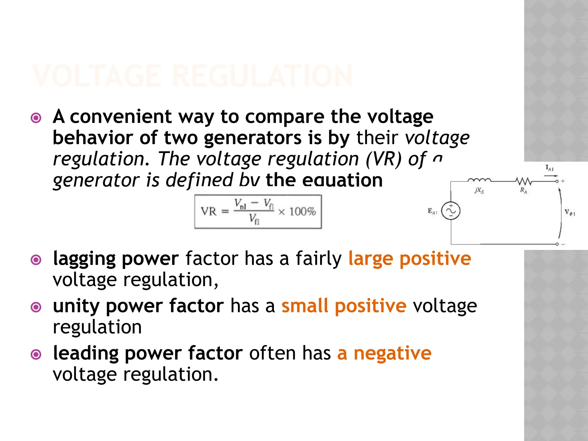
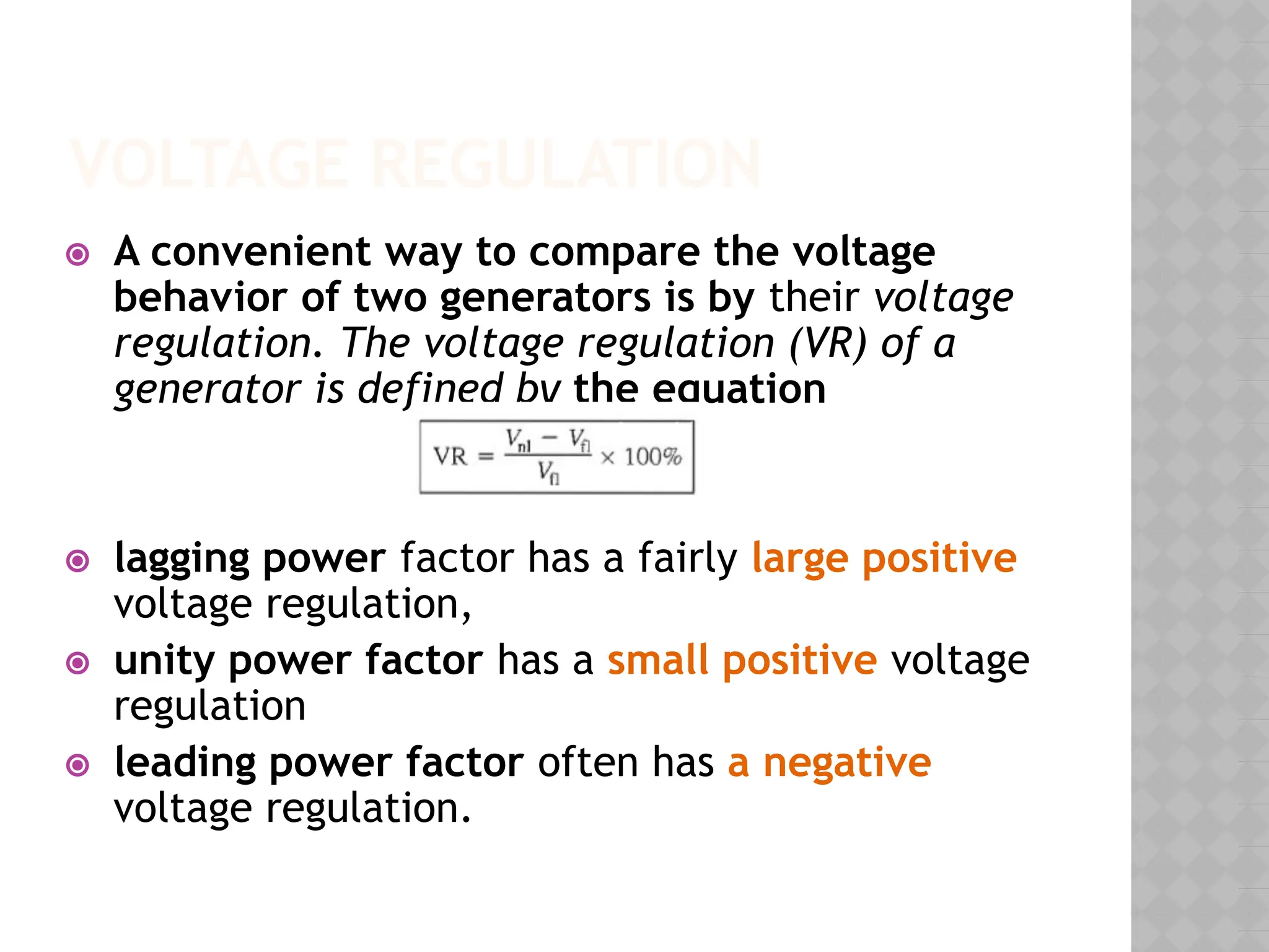
VOLTAGE REGULATION
⦿ Aconvenient way to compare the voltage
behavior of two generators is by their voltage
regulation. The voltage regulation (VR) of a
generator is defined by the equation
⦿ lagging power factor has a fairly large positive
voltage regulation,
⦿ unity power factor has a small positive voltage
regulation
⦿ leading power factor often has a negative
voltage regulation.
39.
KEEPING TERMINAL VOLTAGE
CONSTANT
⦿How to keep VΦ constant if lagging load is
connected?
⦿ Decreasing the field resistance in the
generator increases its field current.
⦿ An increase in the field current increases the
flux in the machine.
⦿ An increase in the flux increases the internal
generated voltage EA = KΦω.
⦿ An increase in EA increases VΦ
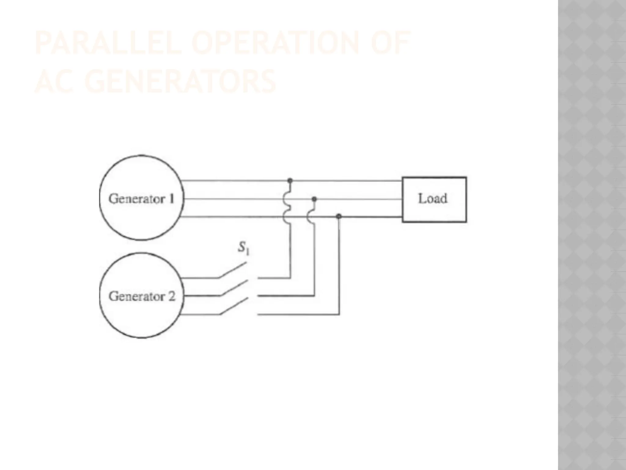
PARALLEL OPERATION OF
ACGENERATORS
Advantages :
⦿ Several generators can supply a bigger load
than one machine by itself.
⦿ Having many generators increases the
reliability of the power system, since the
failure of anyone of them does not cause a
total power loss to the load.
⦿ 3. Having many generators operating in
parallel allows one or more of them to be
removed for shutdown and preventive
maintenance
42.
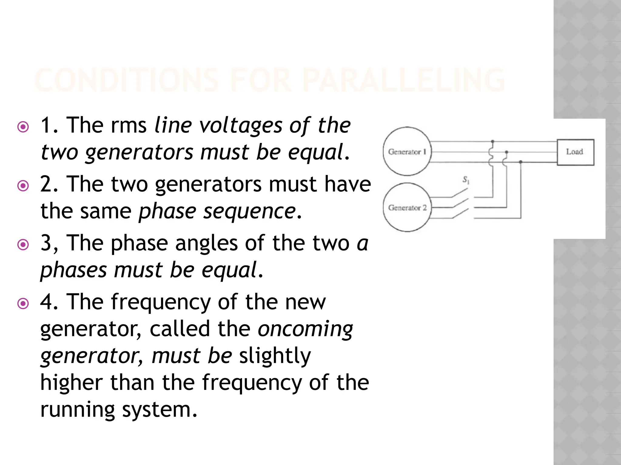
CONDITIONS FOR PARALLELING
⦿1. The rms line voltages of the two
generators must be equal.
⦿ 2. The two generators must have the same
phase sequence.
⦿ 3, The phase angles of the two a phases must
be equal.
⦿ 4. The frequency of the new generator,
called the oncoming generator, must be
slightly higher than the frequency of the
running system.
VOLTAGE REGULATION
⦿ Aconvenient way to compare the voltage
behavior of two generators is by their voltage
regulation. The voltage regulation (VR) of a
generator is defined by the equation
⦿ lagging power factor has a fairly large positive
voltage regulation,
⦿ unity power factor has a small positive voltage
regulation
⦿ leading power factor often has a negative
voltage regulation.
49.
KEEPING TERMINAL VOLTAGE
CONSTANT
⦿How to keep VΦ constant if lagging load is
connected?
⦿ Decreasing the field resistance in the
generator increases its field current.
⦿ An increase in the field current increases the
flux in the machine.
⦿ An increase in the flux increases the internal
generated voltage EA = KΦω.
⦿ An increase in EA increases VΦ
PARALLEL OPERATION OF
ACGENERATORS
Advantages :
⦿ Several generators can supply a bigger load
than one machine by itself.
⦿ Having many generators increases the
reliability of the power system, since the
failure of anyone of them does not cause a
total power loss to the load.
⦿ 3. Having many generators operating in
parallel allows one or more of them to be
removed for shutdown and preventive
maintenance
52.
CONDITIONS FOR PARALLELING
⦿1. The rms line voltages of the
two generators must be equal.
⦿ 2. The two generators must have
the same phase sequence.
⦿ 3, The phase angles of the two a
phases must be equal.
⦿ 4. The frequency of the new
generator, called the oncoming
generator, must be slightly
higher than the frequency of the
running system.
53.
FREQUENCY-POWER
CHARACTERISTICS OF A
SYNCHRONOUSGENERATOR
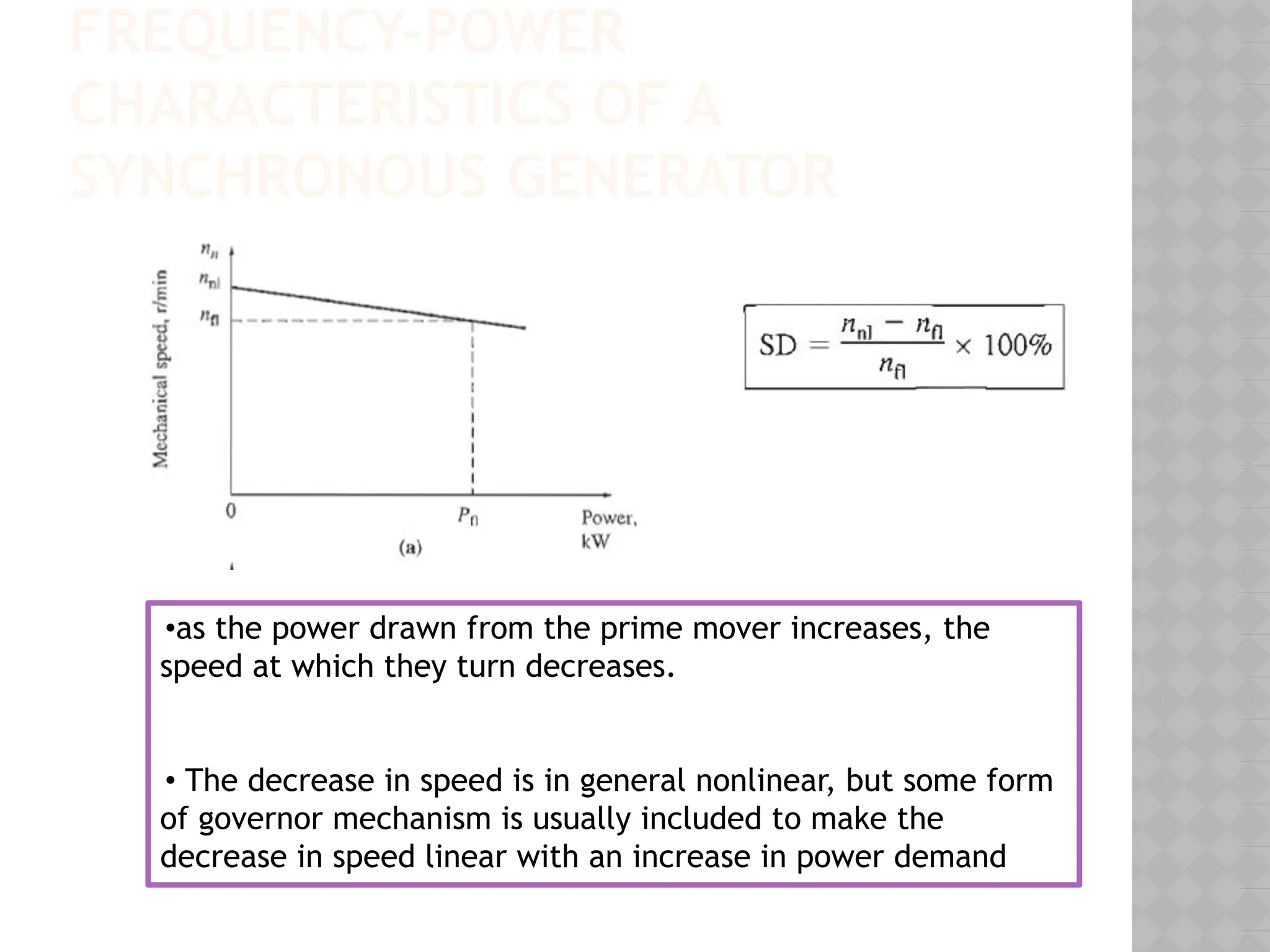
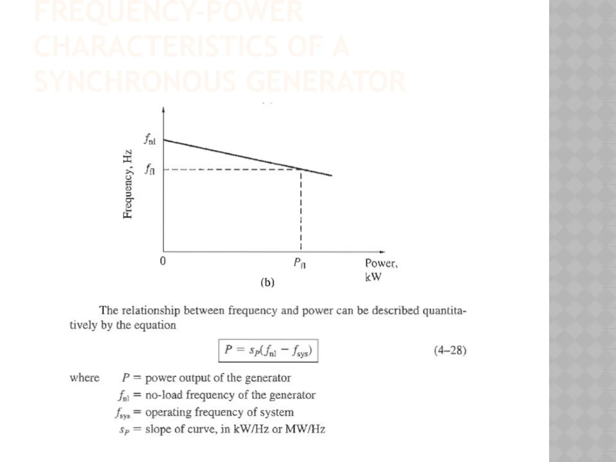
•as the power drawn from the prime mover increases, the
speed at which they turn decreases.
• The decrease in speed is in general nonlinear, but some form
of governor mechanism is usually included to make the
decrease in speed linear with an increase in power demand
TERMINAL VOLTAGE- REACTIVE
POWERCHARACTERISTICS
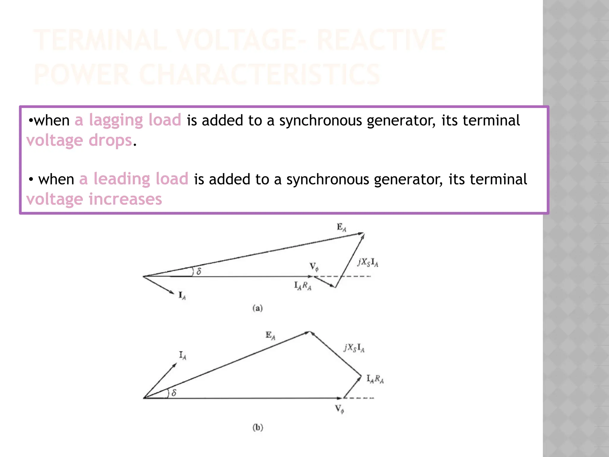
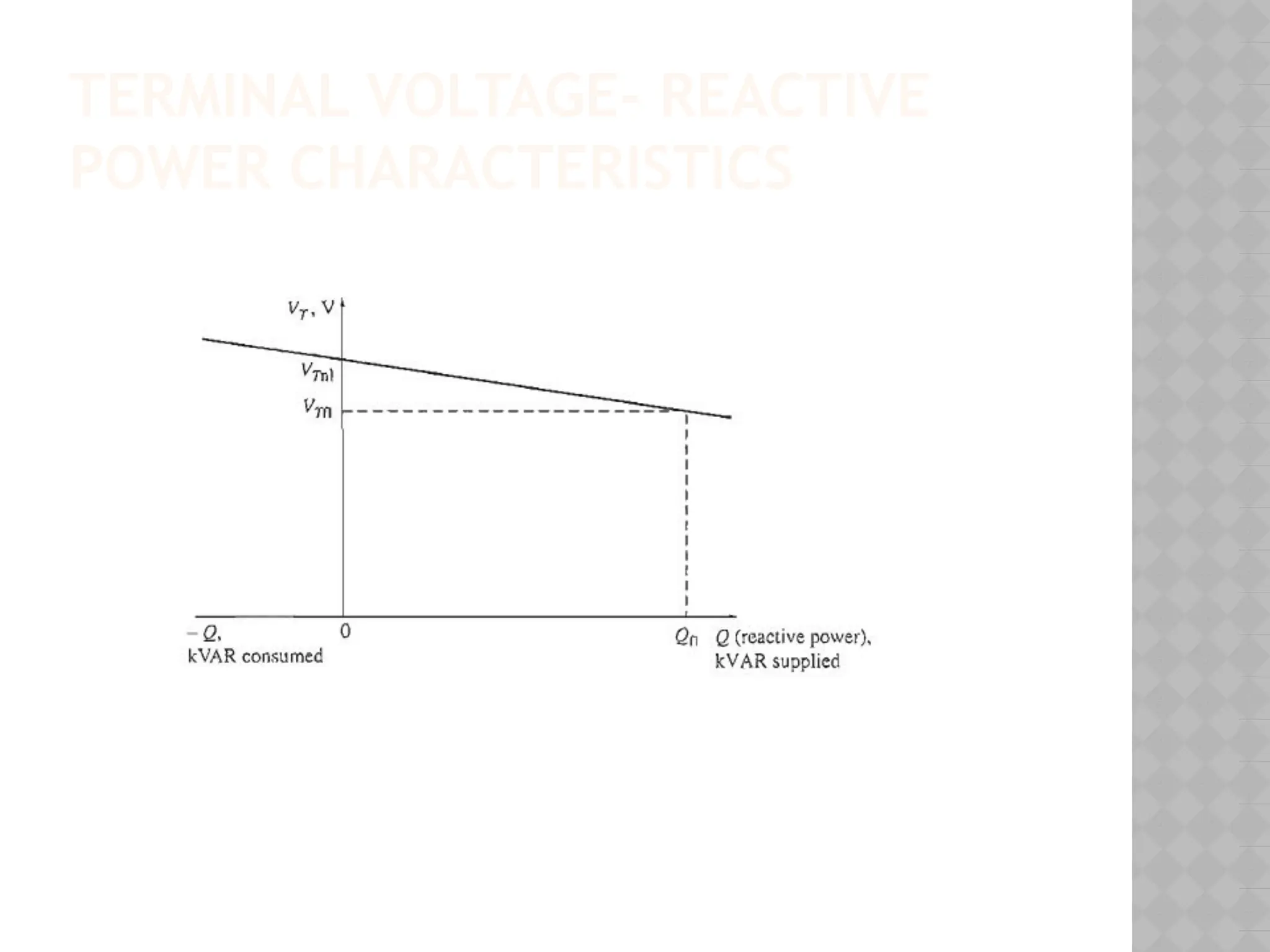
•when a lagging load is added to a synchronous generator, its terminal
voltage drops.
• when a leading load is added to a synchronous generator, its terminal
voltage increases
IMPORTANT POINTS ABOUTREAL
ANS REACTIVE POWER
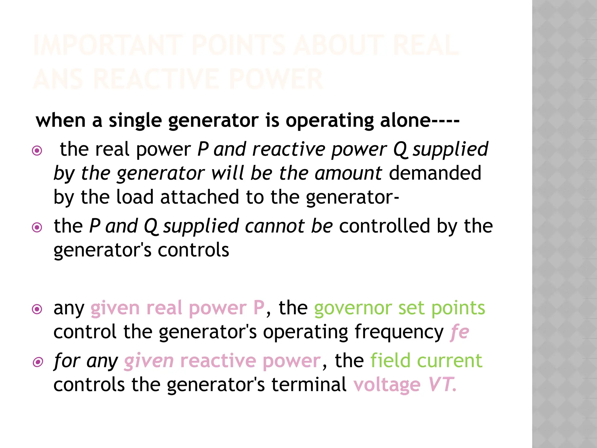
when a single generator is operating alone----
⦿ the real power P and reactive power Q supplied
by the generator will be the amount demanded
by the load attached to the generator-
⦿ the P and Q supplied cannot be controlled by the
generator's controls
⦿ any given real power P, the governor set points
control the generator's operating frequency fe
⦿ for any given reactive power, the field current
controls the generator's terminal voltage VT.
58.
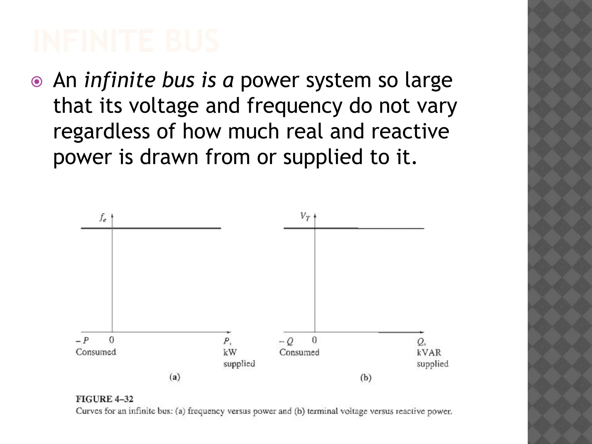
INFINITE BUS
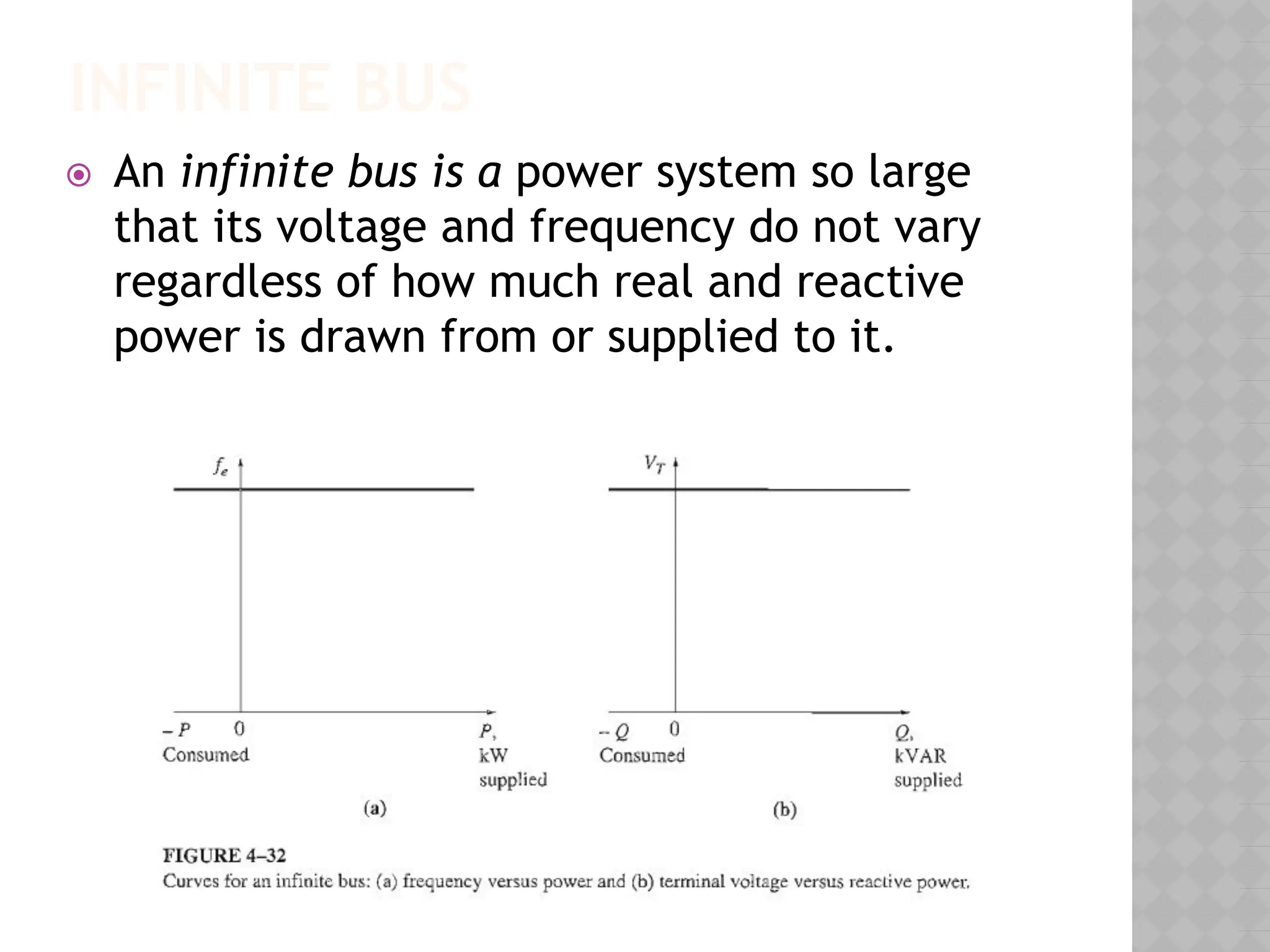
⦿ Aninfinite bus is a power system so large
that its voltage and frequency do not vary
regardless of how much real and reactive
power is drawn from or supplied to it.
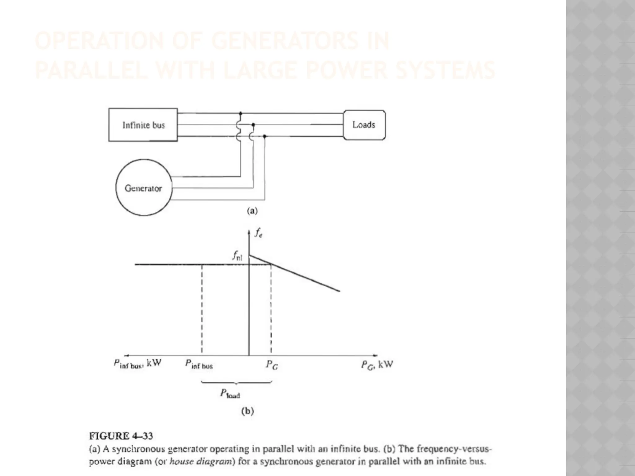
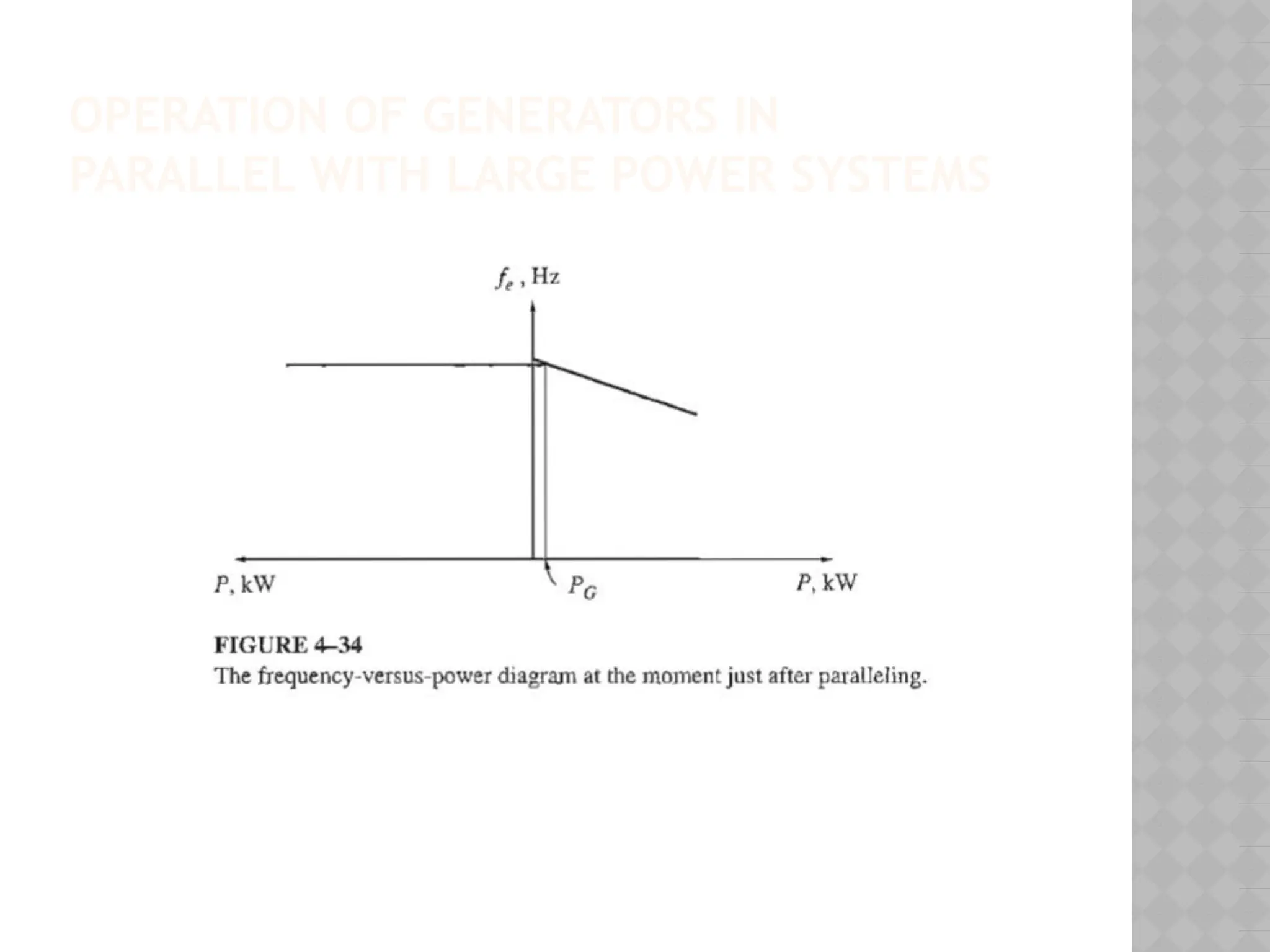
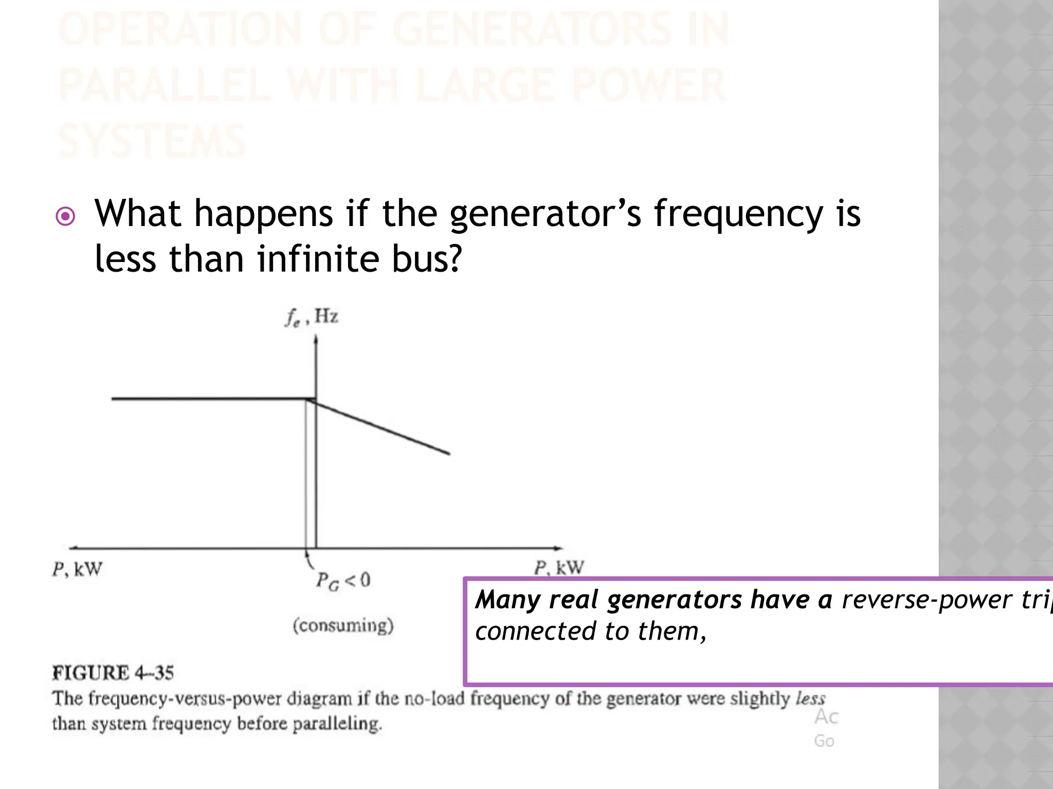
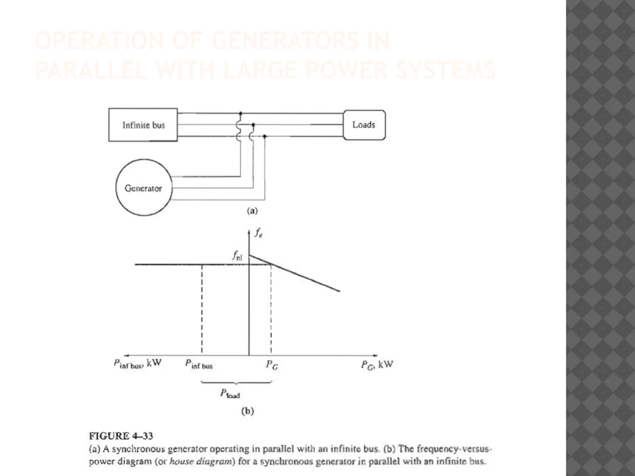
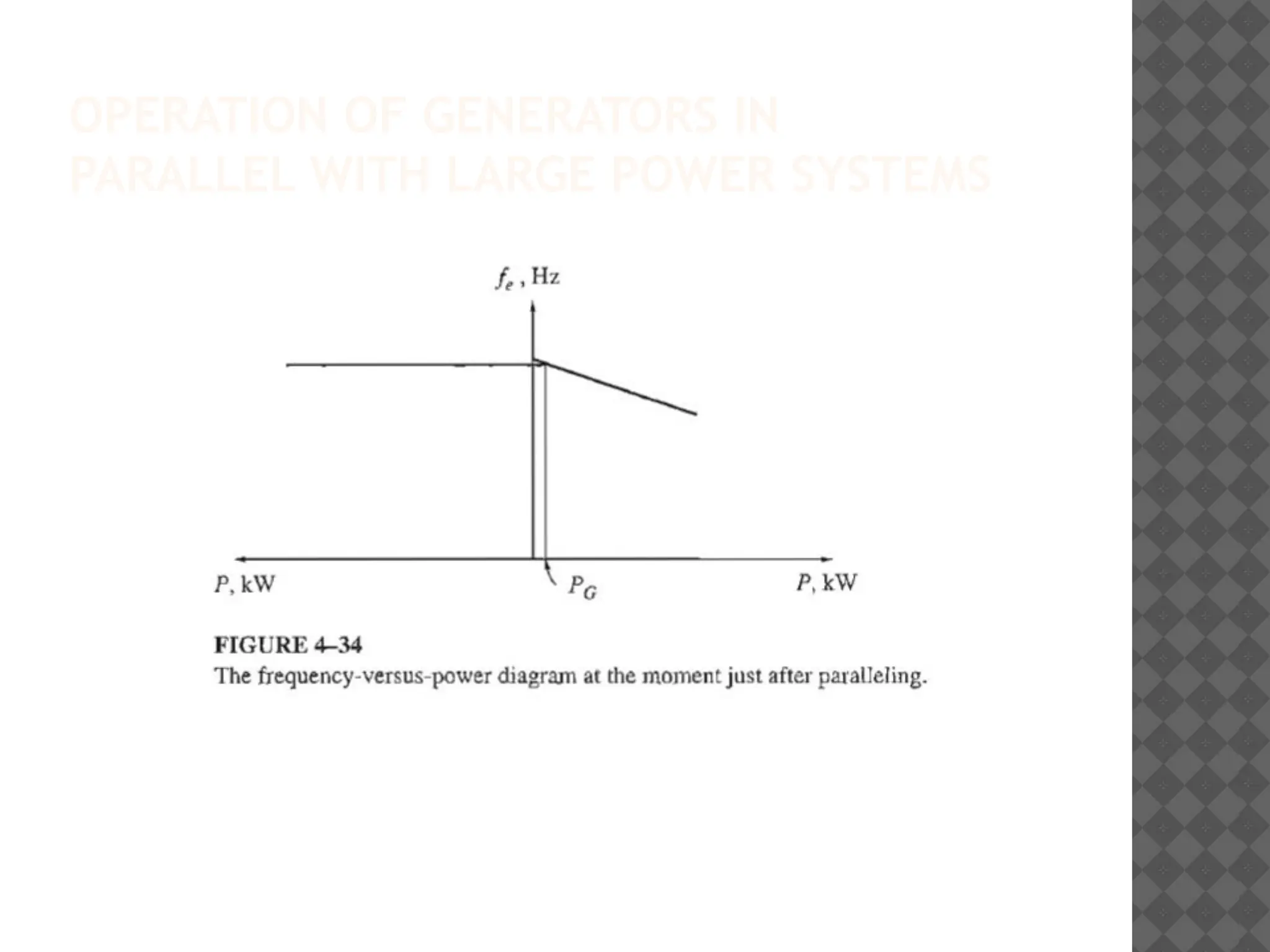
OPERATION OF GENERATORSIN
PARALLEL WITH LARGE POWER
SYSTEMS
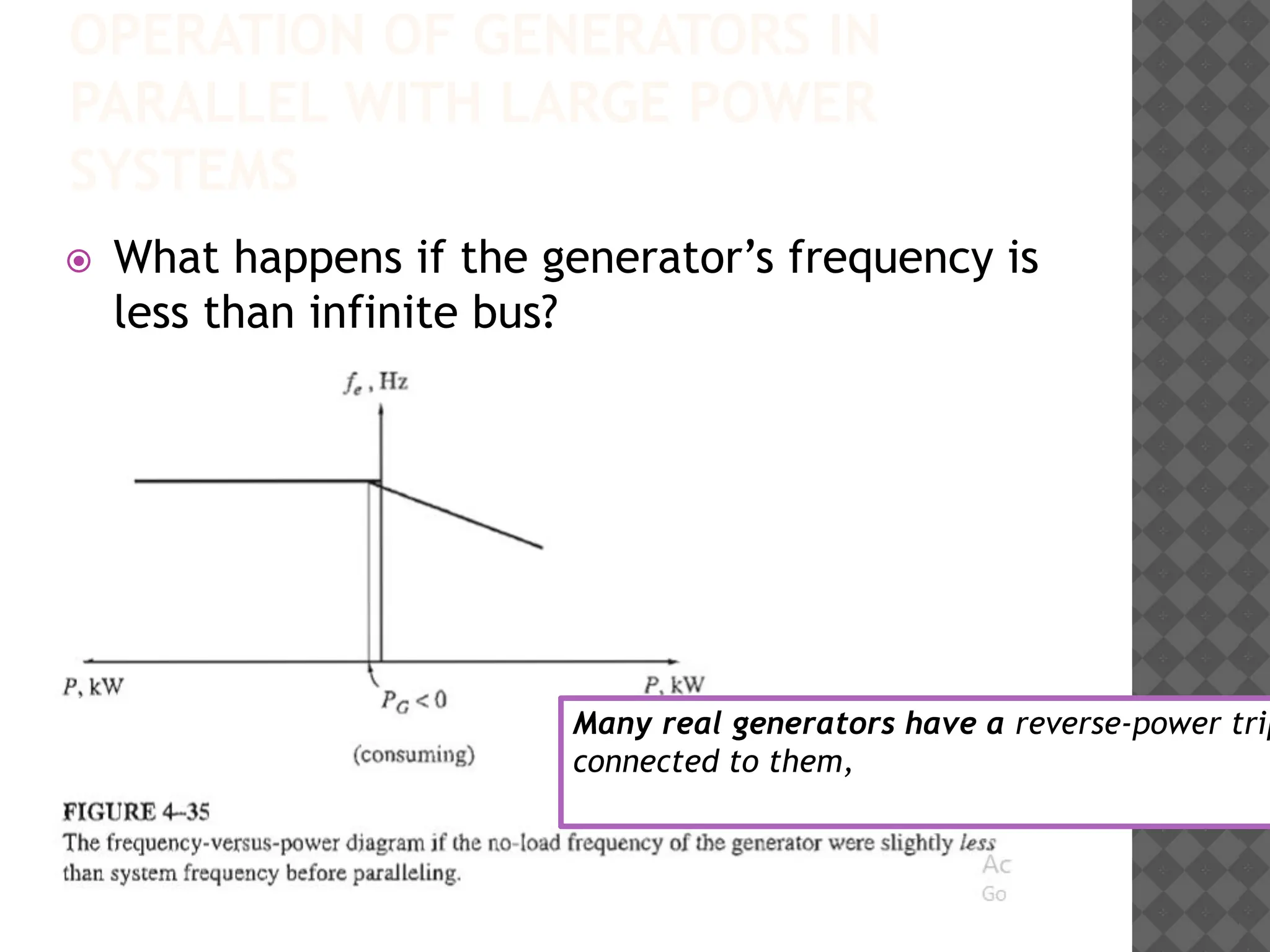
⦿ What happens if the generator’s frequency is
less than infinite bus?
Many real generators have a reverse-power trip
connected to them,
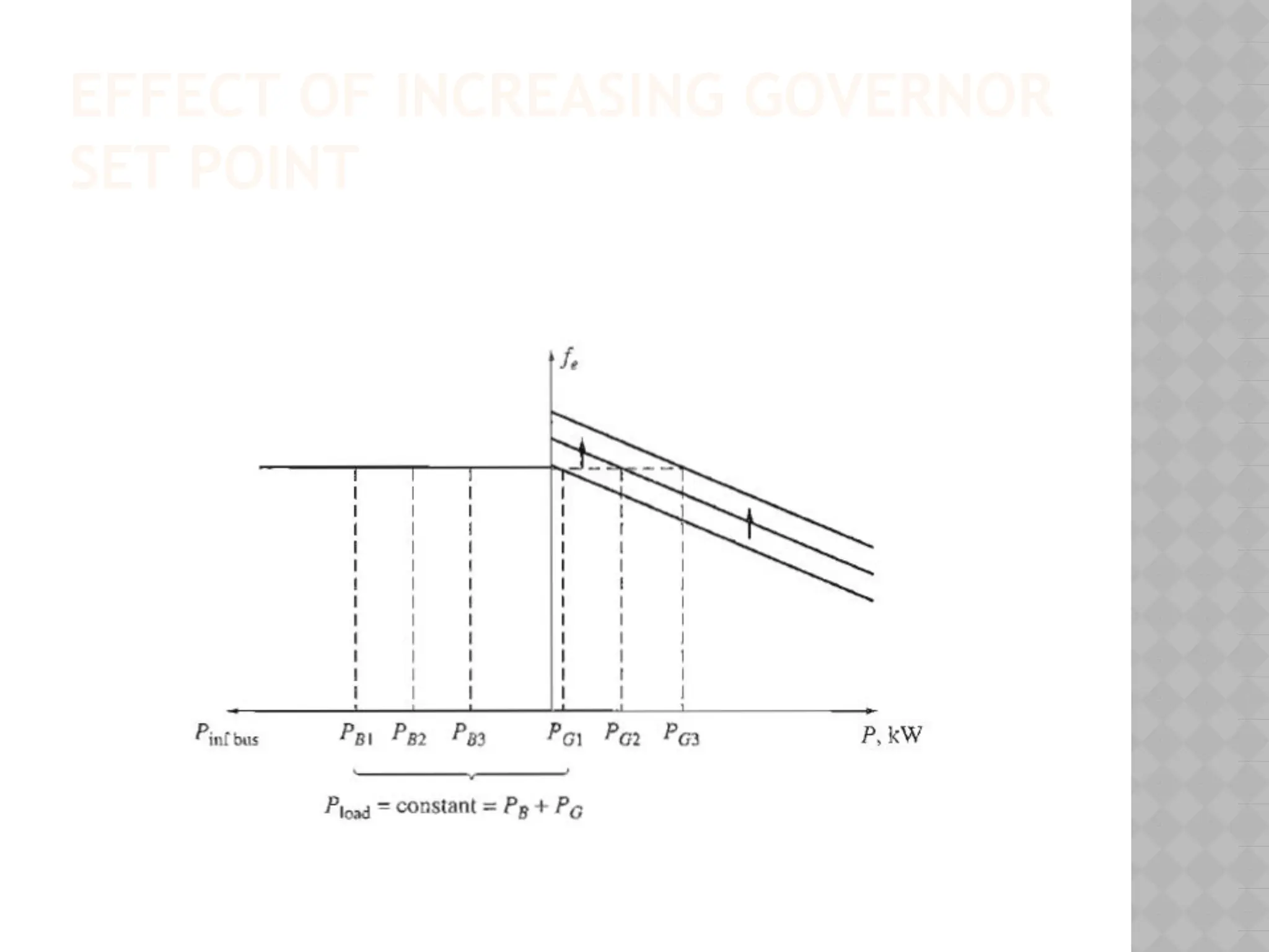
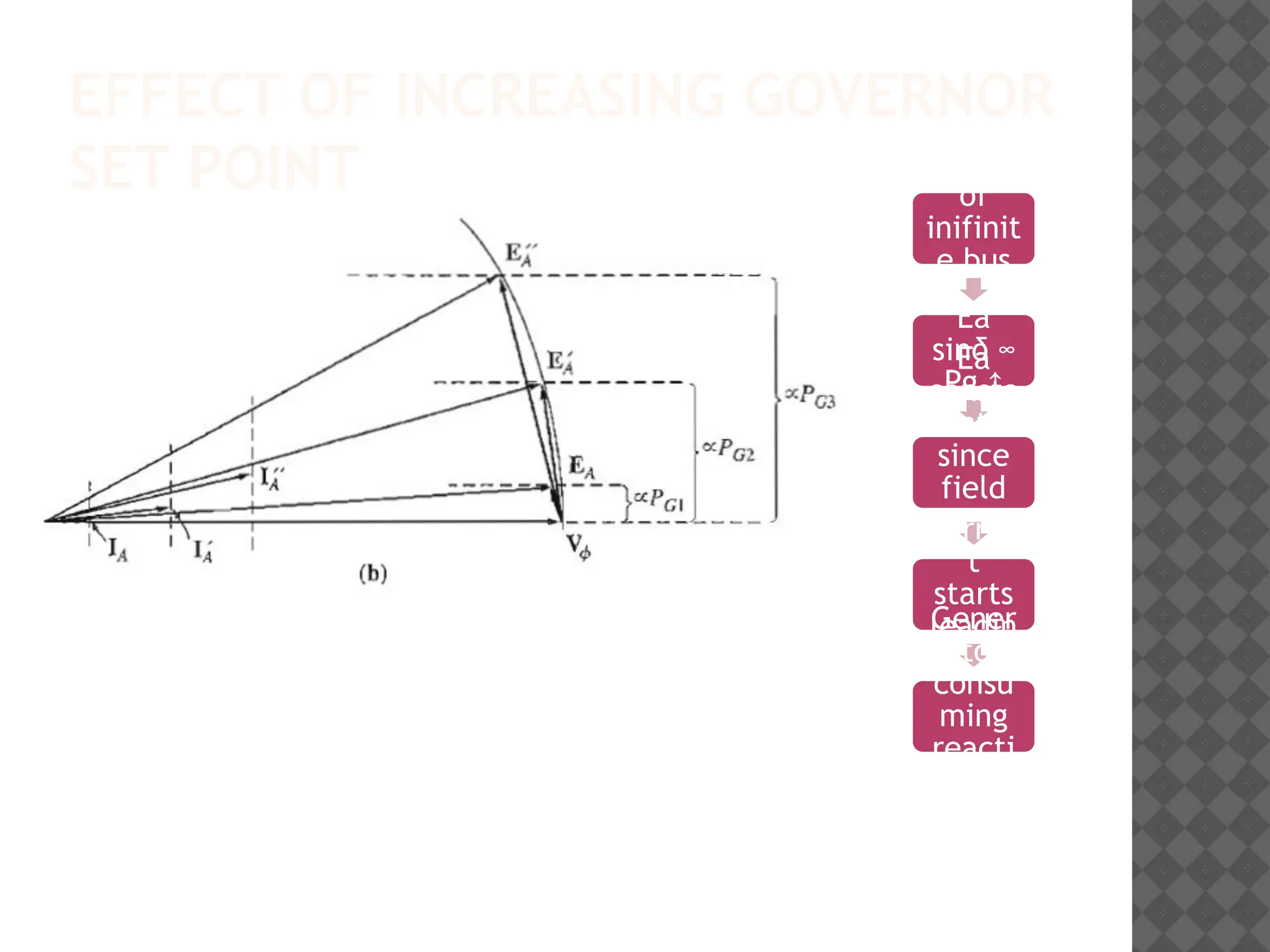
EFFECT OF INCREASINGGOVERNOR
SET POINT
Since
freq
of
inifinit
e bus
const,
Pg ↑
Ea
sinδ ∞
Pg ↑
Ea
consta
nt
since
field
curren
t
const
Curren
t
starts
leadin
g
Gener
ator
consu
ming
reacti
ve
power
64.
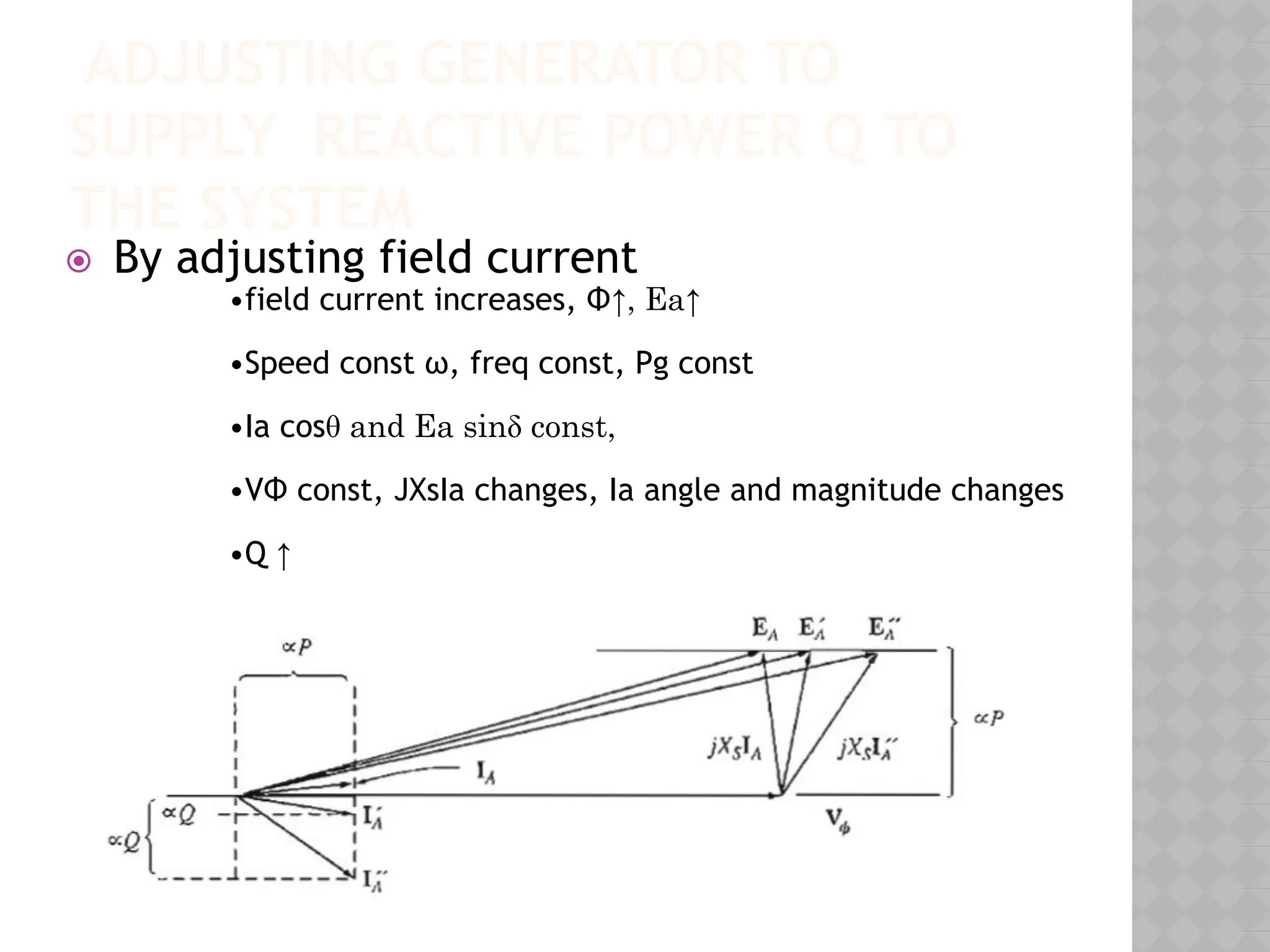
ADJUSTING GENERATOR TO
SUPPLYREACTIVE POWER Q TO
THE SYSTEM
⦿ By adjusting field current
•field current increases, Φ↑, Ea↑
•Speed const ω, freq const, Pg const
•Ia cosθ and Ea sinδ const,
•VΦ const, JXsIa changes, Ia angle and magnitude changes
•Q ↑
INFINITE BUS
⦿ Aninfinite bus is a power system so large
that its voltage and frequency do not vary
regardless of how much real and reactive
power is drawn from or supplied to it.
OPERATION OF GENERATORSIN
PARALLEL WITH LARGE POWER
SYSTEMS
⦿ What happens if the generator’s frequency is
less than infinite bus?
Many real generators have a reverse-power trip
connected to them,
70.
OPERATION OF GENERATORSIN
PARALLEL WITH LARGE POWER
SYSTEMS
⦿ What happens if the generator’s frequency is
less than infinite bus?
Many real generators have a reverse-power trip
connected to them,
EFFECT OF INCREASINGGOVERNOR
SET POINT
Since
freq
of
inifinit
e bus
const,
Pg ↑
Ea
sinδ ∞
Pg ↑
Ea
consta
nt
since
field
curren
t
const
Curren
t
starts
leadin
g
Gener
ator
consu
ming
reacti
ve
power
73.
ADJUSTING GENERATOR TO
SUPPLYREACTIVE POWER Q TO
THE SYSTEM
⦿ By adjusting field current
•field current increases, Φ↑, Ea↑
•Speed const ω, freq const, Pg const
•Ia cosθ and Ea sinδ const,
•VΦ const, JXsIa changes, Ia angle and magnitude changes
•Q ↑
74.
IN SUMMARY
⦿ Thefrequency and terminal voltage of the
generator are controlled by the system to
which it is connected.
⦿ The governor set points of the generator
control the real power supplied by the
generator to the system.
⦿ The field current in the generator controls
the reactive power supplied by the generator
to the system.
75.
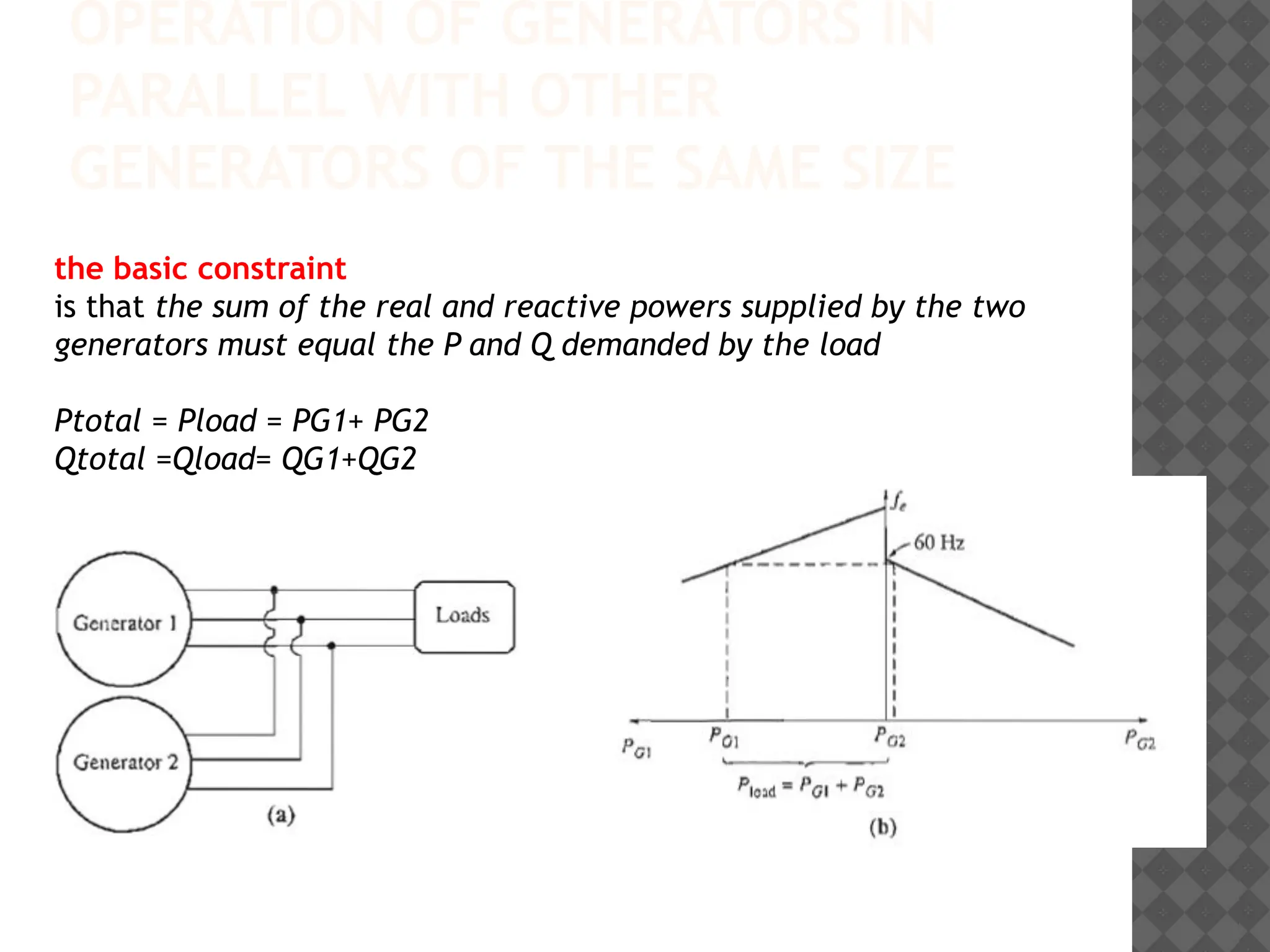
OPERATION OF GENERATORSIN
PARALLEL WITH OTHER
GENERATORS OF THE SAME SIZE
the basic constraint
is that the sum of the real and reactive powers supplied by the two
generators must equal the P and Q demanded by the load
Ptotal = Pload = PG1+ PG2
Qtotal =Qload= QG1+QG2
76.
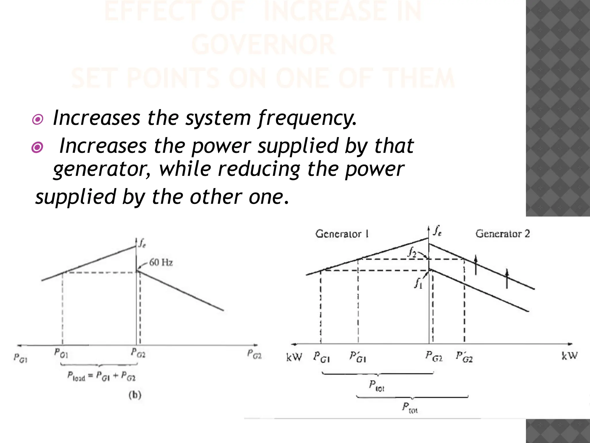
EFFECT OF INCREASEIN
GOVERNOR
SET POINTS ON ONE OF THEM
⦿ Increases the system frequency.
⦿ Increases the power supplied by that
generator, while reducing the power
supplied by the other one.
77.
EFFECT OF INCREASEIN FIELD
CURRENT
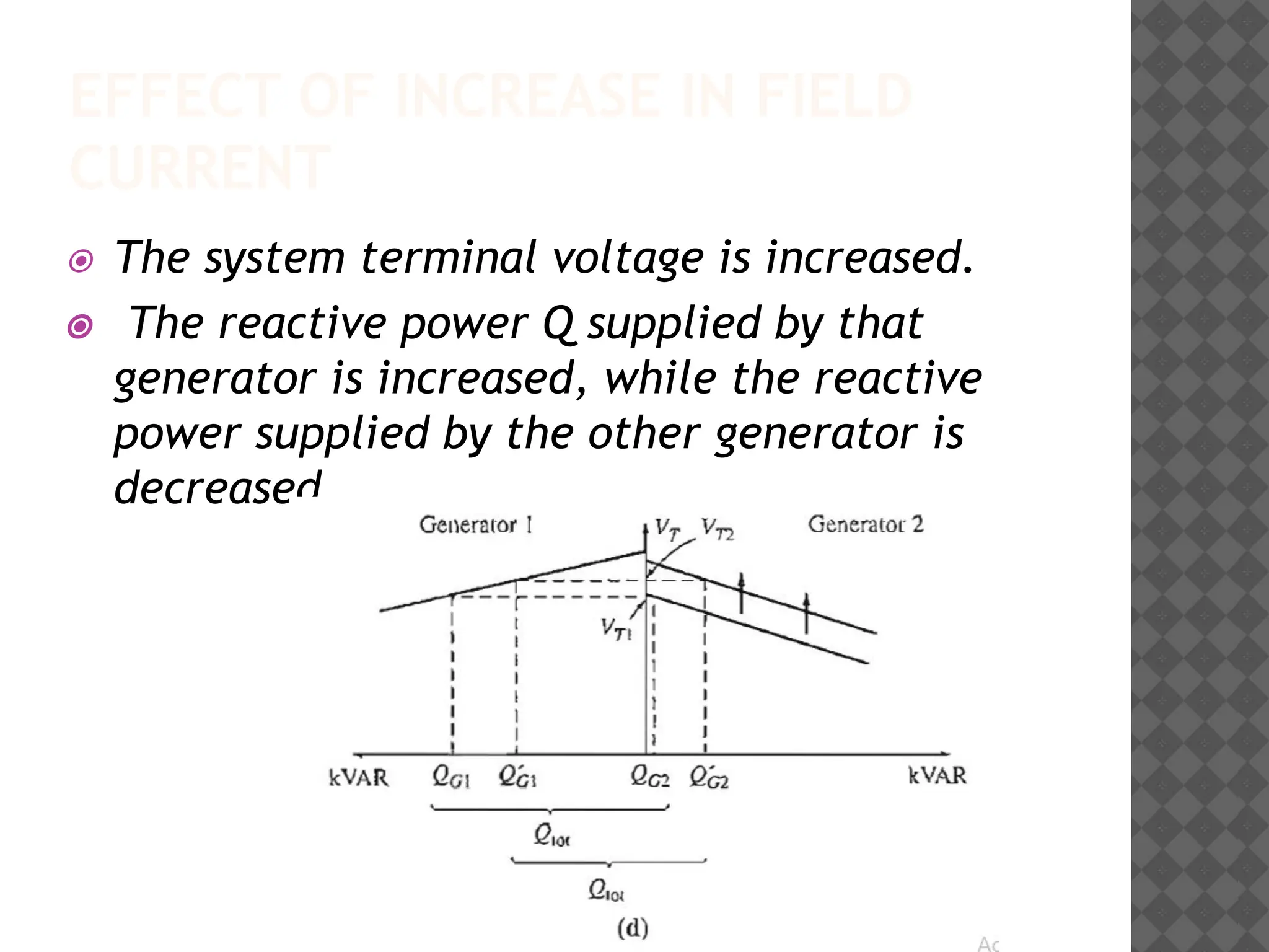
⦿ The system terminal voltage is increased.
⦿ The reactive power Q supplied by that
generator is increased, while the reactive
power supplied by the other generator is
decreased.