The document provides an overview of basic electronics concepts including:
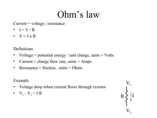
1) Ohm's law defines the relationship between voltage, current, and resistance in circuits.
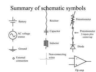
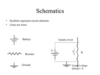
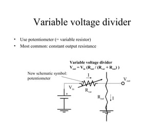
2) Schematics use symbols to represent circuit elements and show how they are connected.
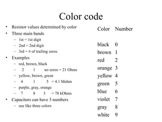
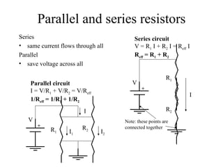
3) Resistors in series and parallel follow specific rules to calculate total resistance.
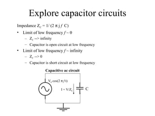
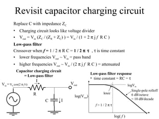
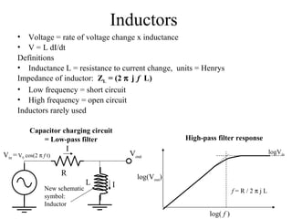
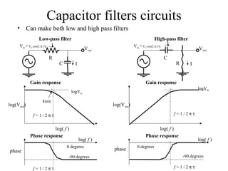
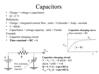
4) Capacitors store charge and their behavior changes with frequency based on impedance.
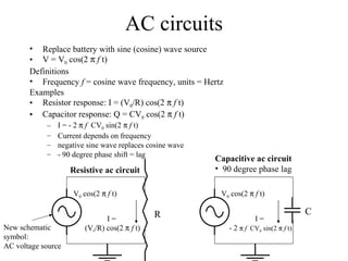
![Simplified notation: ac-circuits V = V 0 cos(2 f t) = V 0 [exp(2 j f t) + c.c.]/2 Drop c.c. part and factor of 1/2 V = V 0 exp(2 j f t) Revisit resistive and capacitive circuits Resistor response: I = (V 0 /R) exp(2 j f t) = V / R = V/ Z R Capacitor response: I = 2 j f CV 0 exp(2 j f t) = (2 j f C) V = V/ Z C Definition: Impedance, Z = effective resistance, units Ohms Capacitor impedance Z C = 1 / (2 j f C) Resistor impedance Z R = R Impedance makes it look like Ohms law applies to capacitive circuits also Capacitor response I = V / Z C](https://image.slidesharecdn.com/07-basic-electronics-100812005027-phpapp01/85/07-basic-electronics-9-320.jpg)