Download to read offline


![Download free ebooks at bookboon.com
Electrical Power
7
Summary
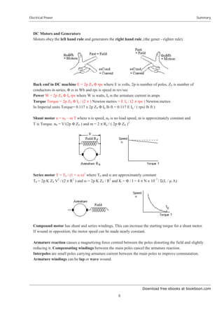
Closed magnetic circuit eg a ring with an air gap or the field circuit of an electrical machine,
mmf = sum of mmfs to drive same ĭ in each part, hence
ĭ = 1.26 N I x 10–6
/ Ȉ(L1/ȝ1A1) Where ĭ is in weber, I in amps, A in m2
and L in metres.
Force on a conductor in a magnetic field F = B I L Newtons where B in tesla, I in amps and L in metres
Force on parallel conductors F = [2 I2
/ d] 10–7
Newtons/metre where I is in amps and d is in metres
With currents in opposite directions, the force is pushing the conductors apart
Pull of Electromagnet Pull = B2
107
/ (8 S ) newtons per m2
of magnet face where B is in tesla
Definition of Volts. The potential difference between two points is 1 volt if 1 watt of power is dissipated
when 1 amp flows from one point to the other. W = V I
Ohms Law (for a direct current circuit with resistance R ohms) V = I R
Power loss in a resistor W = I2
R = V2
/ R
Resistance R = ȡ L (1 + ĮT) / A ohms where ȡ is resistivity in ohms per cm cube, L cm is the length, A
cm2
is the cross sectional area, Į is temp co-eff and T is the temperature in degrees Celsius.
Several sources give Copper ȡ = 1.7 x 10⁻⁶
ohms per cm cube and Į = 0.004. At very low
temperatures, the resistance of some materials falls to zero
Resistance R1 in series with R2. Equivalent resistance = R1 + R2
Resistance R1 in parallel with R2. Equivalent resistance = 1/ ( 1/R1 + 1/R2 )
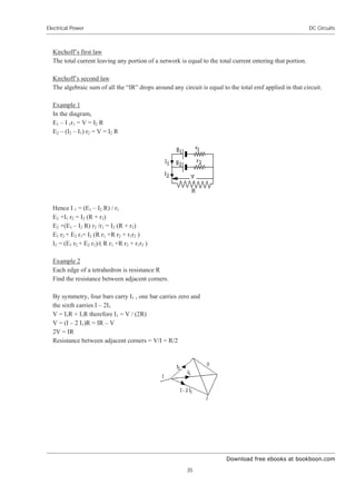
Kirchoff’s first law The total current leaving a point on an electrical circuit = total current entering
Kirchoff’s second law The sum of the voltages round any circuit = net “I R” drop in the circuit
Induced emf E = – N dĭ/dt where E is in volts, N is number of turns and dĭ/dt is in Wb/sec
This equation is the foundation on which Electrical Engineering is based.
Self Inductance E = – L dI/dt where E is in volts, L is inductance in henries and dI/dt is in amps/sec
Self inductance of a coil wound on a ring of permeability P is L = 1.26 N2
P A / S x 10– 6
Henries
where N is number of turns, A is cross sectional area in m2
and S metres is the length of the magnetic
circuit. Experimental results for a coil length S metres, diameter d metres and radial thickness t metres
with air core indicate L = 3 d2
N2
/ (1.2 d + 3.5 S + 4 t ) micro Henries. (t = 0 for a single layer coil).
Energy stored in an inductance = ½ L I2
Joules where L is in henries and I is in amps
Capacitance q = C V where q is in Coulombs (ie amps times seconds), C is Farads and V is volts
Capacitance of a parallel plate condenser area A cm2
and separated d cm and dielectric constant k
C = 1.11 x 10– 6
A k /(4 S d) microfarads
Capacitance of co-axial cylinders radii a and b C = 1.11 x 10– 6
k /[ 2 ln(b/a) ] microfarads per cm
Energy stored in a capacitance = ½ C V2
Joules where C is in farads and V in volts](https://image.slidesharecdn.com/electrical-power-221021180938-fb4e1a70/85/electrical-power-pdf-7-320.jpg)
![Download free ebooks at bookboon.com
Electrical Power
9
Summary
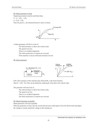
DC shunt generators will fail to excite if there is no residual magnetism or the field resistance is above
the critical value for the speed.
DC series or compound generators require special treatment especially when two or more are in parallel.
Alternating Current AC
AC emf E = Ep Sin (Ȧ t) = Ep Sin (2 S f t) where Ep is peak value, f is frequency and t is seconds. Mean
value of E for a half cycle = 2 Ep / ʌ = 0.636 Ep .
Root mean square (rms) value = Ep / ¥2 = 0.707 Ep
peak factor = (peak value) / (rms value).
form factor = (rms value) / (average value for ½ cycle)
Square wave peak factor = 1, form factor = 1 Sine wave peak factor = 1.41, form factor = 1.11
Triangular wave peak factor = 1.73, form factor = 1.15
Vector representation of AC voltage and current.
The projection on a vertical surface of a vector rotating at constant speed anti clockwise is equal to the
value of an AC voltage or current. The phase angle between V and I is the same as the angle between their
vectors. The diagram shows the Vector representation of current and voltage where the current lags the
voltage This diagram shows the vectors as the peak values. However the rms values are 0.707 times the
peak value. Thus the vector diagram shows the rms values to a different scale. Vector diagrams are rms
values unless stated otherwise.
Power Factor is Cos ij where ij is the angle between the vectors for V and I
Power in a single phase AC circuit W = V I Cos ij watts
Three phase ac. Three voltages with phase angles of 120 degrees between each.
Power in a three phase AC circuit W =¥3 V I Cos ij watts where V is the voltage between lines
Resistance is higher on AC due to eddy current loss.
Rf = R0 [ 1 + 100 S 4
f2
a4
/ (3 ȡ2
)] where Rf and R0 are the AC and DC resistances, f is the frequency,
a is the radius of the conductor in metres and ȡ is the resistance in microhms / cm cube.
V = I R and the voltage V is in phase with the current I.](https://image.slidesharecdn.com/electrical-power-221021180938-fb4e1a70/85/electrical-power-pdf-9-320.jpg)
![Download free ebooks at bookboon.com
Electrical Power
10
Summary
Inductance V = I XL where XL = 2 S f L where L is in Henries. I lags V by S /2.
At 50 cps, XL = 314 L
Capacitance V = I XC where XC = 1/ (2 S f C ) where C is in farads. I leads V by S /2.
At 50 cps XC = 3183/ C where C is in micro farads.
Inductive Impedance Z = R + jX. V = I ¥(R2
+ X2
) I lags V by arc tan (X/R)
Capacitive Impedance Z = R + jX. V = I ¥(R2
+ X2
) I leads V by arc tan (X/R)
Impedance R1 + jX1 in series with R2 + jX2 Equivalent impedance = (R1 + R2) + j(X1 + X2 )
Impedance R1 + jX1 in parallel with R2 + jX2 Put X +ive for inductance, –ive for capacitance
Put Z1 = ¥(R1
2
+ X1
2
) and Z2 = ¥(R2
2
+ X2
2
) Put A = R1 /Z1
2
+ R2 /Z2
2
and B = X1 /Z1
2
+ X2 /Z2
2
Equivalent impedance is R = A / (A2
+ B2
) and X = B / (A2
+ B2
)
Sum of two AC currents.
Add I1 at phase angle ș1 to current I2 at phase angle ș2 and the result is I3 at phase angle ș3
I3 and ș3 are obtained by the vector addition of I1 and I2.
Hysteresis loss Loss = f (area of hysteresis loop) watts/cubic metre where the hysteresis loop is in tesla
and ampere turns/ metre
Energy in magnetic field Energy = B2
107
/ (8 S ) joules per cubic metre where B is in tesla
Eddy current loss in laminated core Loss = S 2
f2
BM
2
b2
/(6 ȡ ) watts per cm3
Where B = BM Sin (2ʌf t) is parallel to the lamination, f is the frequency in Hz, b is the thickness in cm of
the lamination and U is the resistivity in ohms/ cm cube.
Star/Delta transformation
Three impedances R + jX in star = three impedances 3R + 3jX in Delta
AC generators and motors
Fundamental EMF of generator ERMS = 4.44 kP kD N f ĭTOTAL
where N is (number of turns) / (pairs of poles) and kP is the pitch factor. If each coil spans an angle of 2Ȝ
instead of the full angle S between the poles, then kP = Sin (Ȝ). kD is the distribution factor due to the
phase difference of the emf in each conductor. kD = (vector sum of emfs) /(scalar sum of emfs)
For Nth
harmonic, kNP = Sin (nȜ), and kND = Sin (nș/2) / [c Sin (nș/2c)] where ș = S / (no of phases) and c
= slots / phase / pole. Harmonic content can be kept small by suitable values for Ȝ, ș and c.
MMF including harmonics due to a three phase winding in slots
F = (4/ʌ) FMAX (3/2) [k1D Sin (ș – Ȧt) + (k5D/5) Sin (5ș – Ȧt) + (k7D/7) Sin (7ș – Ȧt) + . . . ]](https://image.slidesharecdn.com/electrical-power-221021180938-fb4e1a70/85/electrical-power-pdf-10-320.jpg)

![Download free ebooks at bookboon.com
Electrical Power
12
Summary
Vector Diagram of the emfs, current and mmfs of a synchronous generator.
magnitude of EdL
= magnitude of EL
Suffix L signifies on load condition
Automatic Voltage Regulator adjusts the excitation so that at the system design power factor, the voltage
is correct whatever the current. If however it adjusts the excitation to give the correct voltage at other
power factors, then two machines will not run in parallel. One can supply a huge leading current and the
other a huge lagging current. A “droop” is needed to give a lower voltage if the power factor lags by more
than the system design. This is achieved by the compounding. Faulty Compounding causes unstable
sharing of kVAr which can be quite violent.
System Faults. When a fault occurs, initially dc currents are induced in the damping winding and main
field circuit opposing the demagnetizing effect of the low power factor fault current. These currents die
away exponentially causing the fault current to fall. In extreme cases it can fall below the full load value.
Induction motor Power = 3 V2
(1 – Ȉ) Rr Ȉ / (Rr
2
+ X2
Ȉ2
) watts where the slip Ȉ = (n0 – n ) / n0
Power = 2 S T (1 –Ȉ) n0 watts where T is the torque in Newton metres and n0 is the synch speed
Torque = 3 V2
Rr Ȉ / [ 2 S n0 (Rr
2
+ X2
Ȉ2
) ] Torque is a maximum when Ȉ = Rr / X
Put Ȉ = 1, Starting Torque = 3 V2
Rr / [ 2 S n0 (Rr
2
+ X2
)]
If Rr = X, the maximum torque occurs when the speed is zero but the motor would be very inefficient.
However large motors sometimes have slip rings allowing an external resistance to be added for starting.
The Induction motor speed torque curve. Sometimes there is a kink in the curve at a speed below the
speed for maximum torque due to harmonics in the supply. In such cases, the motor may get stuck at this
speed , called “crawling”.](https://image.slidesharecdn.com/electrical-power-221021180938-fb4e1a70/85/electrical-power-pdf-12-320.jpg)
![Download free ebooks at bookboon.com
Electrical Power
13
Summary
Transformers
Power transformers are usually delta primary and star secondary. The primary is supplied through three
conductors.
Flux ĭmax = [4 S ȝ A N I max / L] x 10–7
weber
EMF Erms = 4.44 N ĭmax f volts
Delta Star Transformation
Three phase load, primary current equals
secondary current times voltage ratio.
A single phase load on the secondary results
in a current on two lines in the primary
governed by the turns ratio, not the voltage ratio.
Third harmonic voltages are the same at each end of each primary winding. Therefore no third harmonic
current flows in the primary and no third harmonic voltage appears in the secondary.](https://image.slidesharecdn.com/electrical-power-221021180938-fb4e1a70/85/electrical-power-pdf-13-320.jpg)


![Download free ebooks at bookboon.com
Electrical Power
19
Electromagnetism and Electrostatics
The force between two adjacent conductors
Two conductors lie parallel and d metres apart in air each carrying a current I amps in opposite directions.
Magnetic force at P due to left hand conductor
B = (2 I /d) x 10–7
tesla into the paper (corkscrew rule)
Mechanical force on įs at P = B I įs newtons
Mechanical force = [2 I2
/ d] 10–7
newtons/metre
where I is in amps and d is in metres. The force is pushing the conductors apart (left hand rule).
Example
Two conductors are 2 cm apart and each carries a current of 400 amps in opposite directions. Find the
force each exerts on the other.
The Force is [2 x 4002
/ (2 x 10⁻²
) ] x 10–7
= 4002
x 10–5
= 1.6 newtons / metre
The magnetizing force at a point on the axis of a circle of wire carrying a current I em units
įH =I įs / d2
Component along axis
įH Sin ș = I įs Sin ș / d2
H = 2S I r Sin ș / d2
= 2S I Sin3
ș / r
By symmetry, the sum of the components of H perpendicular to the axis is zero
Magnetic field due to I,
B = [2Sȝ I Sin3
ș / r] 10–7
where B is in tesla, I is in amps and r is in metres.](https://image.slidesharecdn.com/electrical-power-221021180938-fb4e1a70/85/electrical-power-pdf-19-320.jpg)
![Download free ebooks at bookboon.com
Electrical Power
20
Electromagnetism and Electrostatics
The magnetizing force on the axis of a solenoid
N turns uniformly wound
N Gx /L turns in element Gx
Magnetizing force at P due to element Gx
GH = 2 S I Sin3
ș N Gx / (L r)
But x = r Cot ș
Gx = – r Cosec2
ș Gș
GH = – 2 S I Sin3
ș N r Cosec2
ș Gș /(L r)
GH = – (2 S I N / L) Sin ș Gș
H = œ [– (2 S I N / L) Sin ș ] Gș from ș1 to ș2
= (2 S I N / L) (Cos ș2 – Cos ș1)
If P is at the centre of the solenoid,
ș2 = I and ș1 = SI
+ (4 S I N Cos I ) / L
In Paris or Online
International programs taught by professors and professionals from all over the world
BBA in Global Business
MBA in International Management / International Marketing
DBA in International Business / International Management
MA in International Education
MA in Cross-Cultural Communication
MA in Foreign Languages
Innovative – Practical – Flexible – Affordable
Visit: www.HorizonsUniversity.org
Write: Admissions@horizonsuniversity.org
Call: 01.42.77.20.66 www.HorizonsUniversity.org
Please
click
the
advert](https://image.slidesharecdn.com/electrical-power-221021180938-fb4e1a70/85/electrical-power-pdf-20-320.jpg)

![Download free ebooks at bookboon.com
Electrical Power
22
Electromagnetism and Electrostatics
The cross section area of iron A1 = cross section of air gap A2 = A
B = ĭ / A = (4 S N I x 10–6
/ [L1/ȝ1 + L2] tesla
0.8 = (4 S x 3400 x 10–6
/ [0.628/ ȝ + 5/1000]
0.628 /ȝ + 0.005 = 1.26 x 3400 x 10–6
/0.8 = 5.355 x 10⁻³
1/ȝ = 0.355 x 10⁻³
/ 0.628
ȝ = 1770
What current is needed to give the same flux in a ring with the same number of turns and same air gap but
twice the diameter.
B = (4 S N I x 10–6
/ [L1/ȝ1 + L2]
0.8 = (4 S 680 x I x 10–6
/ [2 x 0.628/ 1770 + 0.005]
I = 5.33 amps
Example
Part of the B – H curve for a ring of iron is;
AmpTurns/cm 5.4 1.3 – 0.4 – 1.0 – 1.4 – 1.6
Tesla 1.1 1.0 0.8 0.6 0 – 0.3
The mean diameter of the ring is 15 cms and it is in two parts separated by 0.2mm
The iron is magnetized by a uniformly distributed coil to a maximum flux density of 1.1 tesla. What are
the ampere turns?
The ampere turns for the iron = 5.4 x ʌ x 15 = 254
The ampere turns for the air gaps are given by
(ampere turns) x 10–6
/(2 x 0.2/1000) tesla = B = 1.1
ampere turns = 349
Total ampere turns = 254 + 349 = 603
Without altering the current, the ring is separated by a further 0.4 mm. Find B
Ampere turns for the air gaps
% (ampere turns) x 10–6
/(2 x 0.6/1000) tesla
ampere turns = B x (2 x 0.6/1000) x 106
/1.26= 955 B
Plot the B-H curve in tesla against ampere turns
And plot (total AT – AT for air gaps)
ie AT = 603 – 955 B
The plots cross when AT for iron + AT for air gaps = 603](https://image.slidesharecdn.com/electrical-power-221021180938-fb4e1a70/85/electrical-power-pdf-22-320.jpg)


![Download free ebooks at bookboon.com
Electrical Power
27
Induced EMF
Self Inductance
The current in a coil causes a magnetic field that links with the coil. Therefore any change in the current
will induce an emf in the coil. The coil is said to have self inductance. The symbol for self inductance is L
and the Engineering unit is the henry. A coil is said to have an inductance of one henry if a rate of change
in current of one amp per second induces an emf of one volt.
E = – L dI/dt where E is in volts, L is in henries, I is in amps and t is in seconds. The minus sign signifies
that the emf opposes the change.
Self Inductance of a coil
A coil is wound with N turns on a ring D metres mean diameter and cross sectional area A square metres
and permeability ȝ.
Let the current be I amps
Magnetising force, H = 4 ʌ N I /( ʌ D) x 10–7
ĭ = ȝ H A Weber
ĭ = 4 ʌ ȝ N I A /( ʌ D) x 10–7
Wb.
emf due to change in I is given by;
E = – N dĭ/dt = - N 4 ʌ ȝ N A /( ʌ D) x 10–7
dI/dt volts
= – (4 N2
ȝ A /D) x 10-7
dI/dt volts
But E = – L dI/dt
Therefore L = (4 N2
ȝ A / D) x 10–7
henries
For a magnetic circuit length S metres
L = 1.26 N2
ȝ A / S x 10–6
henries
Example
A coil of 500 turns is wound on a wooden ring 20 cms diameter
The cross section of the ring is 4 cms diameter. Estimate the self inductance
L = (4ʌ/10) x 5002
x [ʌ x (2/100)2
] x 10–6
/ (ʌ x 0.2) = 2ʌ x 10–4
henries
Energy stored in an inductance
An inductance L henries carries a current I amps.
Let the inductance be disconnected from the supply but allowed to discharge through a resistor. The power
supplied by the inductance;
w = e i watts
where w, e and i are the values of power, emf and current at any instant during the discharge.
e = –L di/dt w = – L i di/dt](https://image.slidesharecdn.com/electrical-power-221021180938-fb4e1a70/85/electrical-power-pdf-27-320.jpg)

![Download free ebooks at bookboon.com
Electrical Power
29
Induced EMF
Inductance discharged through a resistance
When an inductance L henries is discharged through a resistance R ohms, the current decays exponentially
with a time constant T
Let I0 be the current at t = 0
E = – L di/dt and E = iR
(L/i)di = R dt
œ(1/i) di from I0 to i = – (R/L) œdt from 0 to t
ln(i/I0) = – (R/L)t
i = I0 e –(R/L) t
But i = I0 e –( t/T)
for exponential decay with time constant T
Hence the current decays exponentially with a time constant T = L/R
Inductance charged through a resistance from constant volt supply
When t = 0, the current is zero
At time t, V = L di/dt + iR
Multiply by integrating factor eR/L t
V eR/L t
= L eR/L t
di/dt + R i eR/L t
= L d/dt [ i eR/L t
]
Integrating
(L/R) V eR/L t
= L[ i eR/L t
] + Const
When t = 0, i = 0 therefore Constant = (L/R)V
i = V/R – V/R e–R/L t
= (V/R) (1 – e–R/L t
)
The current rises exponentially with a time constant T = L/R towards I = V/R
Power to inductance charged through a resistance
Power to inductance W = v i = i Ldi/dt
W = [(V/R) (1 – e-R/L t
)] [ L (V/R) (R/L) e–R/L t
]
W = (V2
/R) (e–R/L t
) (1 – e–R/L t
)
Put x = (e-R/L t
) W = (V2
/R) (x – x2
)
dW/dx = (V2
/R) (1 – 2x)
dW/dx = 0 when x = ½
d2W/dx2
= (V2
/R) (– 2) which is negative
Therefore W is a maximum when x = ½
WMAX = (V2
/R) [ ½ – ( ½)2
]
= V2
/(4R) and is independent of L
Change in Flux and Quantity
A coil with N turns is connected to a circuit with a total resistance R ohms.
The Flux through the coil is ĭ
– N dĭ/dt = I R = dq/dt R
Integrate wrt t from 1 to 2
N (ĭ1 – ĭ2 ) = R (q2 – q1 ) where ĭ is in weber, q is in coulombs and R is in ohms](https://image.slidesharecdn.com/electrical-power-221021180938-fb4e1a70/85/electrical-power-pdf-29-320.jpg)
![Download free ebooks at bookboon.com
Electrical Power
30
Induced EMF
Capacitor
A capacitor stores a quantity of electricity. The storage is proportional to the voltage and capacitance.
The symbol for capacitance is C
The SI unit is the farad = coulombs/volt but this is too large for practical use. The Engineering unit is the
microfarad (ȝF) = 10–6
farad.
q = C V where C, q and V are in the same units
Conversion of esu units to mks units
1 esu of quantity = 1 / (3 x 10¹⁰
) emu of quantity = 1/(3 x 109
) coulomb
where 3 x 10¹⁰
cm/sec is the speed of light (actually 2.998 x 10¹⁰
)
1 esu of pd = 3 x 10¹⁰
emu of pd = 3 x 1010
x 10– 8
volts = 3 x 10²
volts
thus 1 esu of capacitance = (1 esu of quantity) / (1 esu of pd)
= [1/(3 x 109
) coulomb] / [3 x 10²
volts]
= [1/(9 x 1011
)] coulombs / volt
= [1.11 x 10⁻¹²
] coulombs / volt or farads
= [1.11 x 10⁻¹²
106
] ȝF
= [1.11 x 10– 6
] ȝF
hence (value of C in ȝF) = 1.11 x 10– 6
x (value of C in es units)
Parallel plate condenser
Let area of plate = A sq cm
and charge on the plate = ı per unit area
Total normal electric induction
= 4ʌ ı / k per unit area
V equals the work done in taking the charge from one plate to the other
V = œF dx = 4ʌ ı d / k where d is the distance between the plates in cms
The capacitance of the condenser C = q / V = Aı / V = A k / (4ʌ d) in es units
C = 1.11 x 10⁻⁶
x A k / (4ʌ d) microfarads
Parallel plate condenser with two insulations
Electric induction ij = 4ʌ ı
Fa = ij / ka = 4ʌ ı / ka per unit area
Fb = ij / kb = 4ʌ ı / kb per unit area
V = 4ʌ ı a / ka + 4ʌ ı b / kb
Capacitance per unit area = ı / V = 1/[4ʌ(a / ka + b / kb) es units](https://image.slidesharecdn.com/electrical-power-221021180938-fb4e1a70/85/electrical-power-pdf-30-320.jpg)
![Download free ebooks at bookboon.com
Electrical Power
31
Induced EMF
C = 1.11 x 10⁻⁶
/[4ʌ(a / ka + b / kb) ȝF per square cm
Co-axial cylinders radius a and b, length L
Let charge per unit length = ı
Gauss’s theorem ij 2ʌ r L = 4ʌ ı L
ij = 2 ı / r
F = ij / k = 2 ı / (r k)
V = œ F dr from a to b
= (2 ı / k) ln (b / a)
Capacitance C = ı / V = k / [2 ln (b / a) ] in es units
C = 1.11 x k x 10-6
/ [2 ln (b / a) ] ȝF per cm
Develop the tools we need for Life Science
Masters Degree in Bioinformatics
Bioinformatics is the
exciting field where biology,
computer science, and
mathematics meet.
We solve problems from
biology and medicine using
methods and tools from
computer science and
mathematics.
Read more about this and our other international masters degree programmes at www.uu.se/master
Please
click
the
advert](https://image.slidesharecdn.com/electrical-power-221021180938-fb4e1a70/85/electrical-power-pdf-31-320.jpg)
![Download free ebooks at bookboon.com
Electrical Power
32
Induced EMF
Example 1
Calculate the capacitance per kilometer of a lead covered cable where a = 2.5 mm and insulation is 2 mm
thick and k = 4. Therefore b = 4.5 mm.
Capacitance / cm = 1.11 x 4 x 10–6
/ [2 ln (4.5 / 2.5) ] ȝF
Capacitance / kilometer = 1.11 x 4 x 10–6
/ [2 ln (4.5 / 2.5) ] x 100 x 1000 = 0.38 ȝF
Example 2
Calculate the capacitance if the outer 1 mm of the insulation has k = 2
ij = 2 ı / r throughout the cable.
For inner 1 mm, F1 = ij /4 = 2 ı /(4 r)
For outer 1 mm, F2 = ij /2 = 2 ı /(2 r)
V = œ F1 dr from .25 to .35 + œ F2 dr from .35 to .45
= 2 ı [(1/4) ln(.35/.25) + (1/2)ln(.45/.35)]
Hence ı / V = 2.37 esu / cm = 2.37 x 10⁵
esu / km
Capacitance = 1.1 x 10–6
x 2.37 x 105
ȝF per km = 0.26 ȝF per km
Energy stored in a capacitor
Work done in increasing the charge by įq = V įq
But q = C V
įq = C įV
Work done = CV įV
Energy stored œ CV dV from V = 0 to V = V
Energy stored = (1/2) C V2
where energy is in joules, C is in farads and V is in volts
Capacitor discharged through a resistance
At time t, q = Cv and v = iR and i = dq/dt
q = CR dq/dt
Integrate from q0 to q, CR ln(q/q0 ) = – t
q = CR i, therefore CR ln( i/i0 ) = – t hence i = i0 e– (1/CR) t
The current decays exponentially with a time constant T = CR
Capacitor charged through a resistance from a supply at constant voltage V
When t = 0, q = 0
At time t, q = Cv and V = iR + q/C and i = dq/dt
q/CR + dq/dt = V/R
Multiply by the integrating factor e(1/CR) t
d/dt[ q e(1/CR) t
] = (V/R) e(1/CR) t
Integrating
q e(1/CR) t
= (V/R) (CR) e(1/CR) t
+ constant = (CV) e(1/CR) t
+ constant
When t = 0, q = 0 therefore constant = – CV
q = CV [ 1 – e– (1/CR) t
]
The charge rises exponentially with a time constant T = CR towards Q = CV](https://image.slidesharecdn.com/electrical-power-221021180938-fb4e1a70/85/electrical-power-pdf-32-320.jpg)

![Download free ebooks at bookboon.com
Electrical Power
34
DC Circuits
DC Circuits
Internal resistance of a cell
The current I in a circuit of resistance R connected to a cell of voltage E and internal resistance r is
I = E/(R + r)
If V is the voltage across R
then V = IR
hence r = (E – V)/I
E is the voltage on open circuit and can be measured with a potentiometer
hence r can be found.
Alternatively;
If I1 is the current with Resistance R1 and I2 is the current with Resistance R2
Then I1 ( R1 + r) = E = I2 (R2 + r)
Thus r = (I2 R2 – I1 R1) / (I1 – I2)
Resistances in series
V1 = I R1 V2 = I R2
V = I R V = V1 + V2
I R = I R1 + I R2
Hence R = R1 + R2
Resistances in parallel
V = I1 R1 V = I2 R2
V = I R I1 = V / R1
I2 = V / R2 I1 + I2 = I =V / R
V / R = V / R + V / R2
R = 1 / [ (1 / R1) + ( 1 / R2)]](https://image.slidesharecdn.com/electrical-power-221021180938-fb4e1a70/85/electrical-power-pdf-34-320.jpg)
![Download free ebooks at bookboon.com
Electrical Power
36
DC Circuits
Thevenin’s Theorem
To find the current in a resistance r, a branch of a network, remove the branch and find the voltage E
across the ends of the branch. Short circuit all sources of emf and find the resistance R of the network
between the ends of the branch with the branch removed. The current in the branch is E / (R + r).
Example
Find the current in branch QS
All values are in ohms.
4 ohm resistor in parallel with 1 and 2
equals 1/(1/4 + 1/3) = 12/7
Remove QS and
voltage between Q and S = E (5 + 12/7) / (8 + 12/7) = 0.691 E
Resistance between Q and S = 1/[1/3 +1/(5 + 12/7)] = 2.074
Current in QS = 0.691 E / (2.074 + 2) = 0.170 E
Wheatstone Bridge
A Wheatstone Bridge consists of four resistances connected as shown. D is a galvanometer to detect any
current.
If the galvanometer cannot detect any current, then P/Q = R/S.
For example, P, Q and R are resistances that can be switched to any value within a range. An unknown
resistance S is connected and P, Q and R adjusted till the galvanometer shows the bridge to be balanced.
Hence the value of S can be found.
Potentiometer
A voltage V connected internally through a high resistance cannot be measured by a meter. As soon as the
meter takes current, the voltage drops.
A potentiometer allows the voltage to be measured without taking any current. A dc supply and voltmeter
E are connected across a uniformly wound rheostat](https://image.slidesharecdn.com/electrical-power-221021180938-fb4e1a70/85/electrical-power-pdf-36-320.jpg)


![Download free ebooks at bookboon.com
Electrical Power
39
Alternating Current (AC)
Root Mean Square value (rms value)
Integrate the value of e2
over a full cycle to obtain the average value of e2
2S average value of e2
) = œ Ep
2
Sin2
T dT from 0 toS
= ½ Ep
2
ˆ (1– Cos 2T dT from 0 to 2S
= ½ Ep
2
[T– Sin 2T@from 0 to 2S
= ½ Ep
2
( 2S – 0 – 0 + 0) = S Ep
2
Hence average value of e2
= ½ Ep
2
Take the square root to obtain the rms value
Erms = Ep / / 2 = 0.707 Ep
The power of an electrical circuit is proportional to e2
hence the use of the Erms value Unless stated
otherwise, the value given for an AC voltage or current is the rms value. A DC voltage is equivalent to an
AC voltage with the same rms value.
Peak factor and Form factor
Peak factor = (peak value) / ( rms value)
Form factor = (rms value) / (av value for ½ cycle)
Sine wave form factor = (0.707) / ( 0.636 Ep) = 1.11
Triangular wave form E = Ep ș/ ( ʌ /2) between 0 and ʌ /2
Eav = 0.5 Ep
Erms = Ep ¥[ œ {ș2
/ ( ʌ /2) 2
} d ș / ( ʌ /2)]
with the integral from 0 to ʌ /2
Erms = Ep / ( ʌ /2) 3/2
¥[ œ ș2
d ș ]
Erms = Ep / ( ʌ /2) 3/2
¥[ ș3
/3 d ș ] from 0 to ʌ /2
Erms = Ep / ( ʌ /2) 3/2
¥[ (ʌ /2)3
/3] = Ep /¥3 = 0.577 Ep
Triangular wave Form factor = 0.577 Ep / 0.5 Ep = 1.15
Square wave Eav = Ep and Erms = Ep
Square wave form factor = Ep/Ep 1
Summarising
Sine wave form factor = 1.11 peak factor = ¥2 = 1.41
Square wave form factor = 1 peak factor = 1
Triangular wave form factor = 1.15 peak factor = ¥3 = 1.73
Thus the form factor is a measure of how peaky the wave is.
Example
Find the average value for half cycle, the rms value and the form factor of the wave shown where 3T = ʌ](https://image.slidesharecdn.com/electrical-power-221021180938-fb4e1a70/85/electrical-power-pdf-39-320.jpg)
![Download free ebooks at bookboon.com
Electrical Power
40
Alternating Current (AC)
Average value for ½ cycle = 2 x 200/3 = 133 volts
rms value = ¥[{2 x œ2002
(t/T)2
dt + 2002
xT}/ʌ] where the integral is from 0 to T
= ¥[2002
x { 2 t3
/( 3T 2
) + T}]/ʌ where the integral is from 0 to T
= ¥[2002
x { 2T3
/( 3T 2
) + T}]/ʌ = 200 x ¥ [ 5T/3]/ʌ where T = ʌ/3
= ¥[2002
x {5ʌ / 9}/ʌ] = ¥2002
x [ 5 / 9]
= 200 x ¥5 / 3 = 149 volts
Form factor = rms value /average value = 149 / 133 = 1.12
Frequency
The number of complete cycles per second is the frequency in Hertz (Hz)
Mains electricity is at a frequency of 50 Hz in Europe and 60 Hz in America.
e = Ep Sin Zt so the time taken for N cycles is given by ZT = 2 SN
Therefore T = 2 SN / Z But the time taken for N cycles = N / f
Hence N / f = 2 SN / Z thus Z = 2 Sf
Do you want your Dream Job?
More customers get their dream job by using RedStarResume than
any other resume service.
RedStarResume can help you with your job application and CV.
Go to: Redstarresume.com
Use code “BOOKBOON” and save up to $15
(enter the discount code in the “Discount Code Box”)
Please
click
the
advert](https://image.slidesharecdn.com/electrical-power-221021180938-fb4e1a70/85/electrical-power-pdf-40-320.jpg)
![Download free ebooks at bookboon.com
Electrical Power
41
Alternating Current (AC)
Vector representation of AC
Let the vector Vp rotate anti-clockwise at a speed of Ȧ radians/sec.
The projection of Vp on a vertical is sinusoidal with respect to time.
Let another vector Ip at an angle of ) with Vp also rotate anti-clockwise at
the same speed of Ȧ radians/sec.
The projection of Ip on the vertical is sinusoidal displaced ) behind of Vp.
The vectors Vp and Ip represent the two sinusoidal quantities.
Thus alternating currents and voltages can be represented by vectors.
Addition of two AC voltages or two AC currents
Let V1 and V2 be two AC voltages at the same frequency but of different magnitude and phase angle.
V1 = Vp1 Sin (Ȧt + ș1) and V2 = Vp2 Sin (Ȧt + ș2)
V1+V2=Vp1[Sin Ȧt Cosș1 + Cos Ȧt Sinș1] + Vp2[Sin Ȧt Cosș2 + Cos Ȧt Sinș2]
= Sin Ȧt [Vp1 Cosș1 + Vp2 Cosș2] + Cos Ȧt [Vp1 Sinș1 + Vp2 Sinș2]
Put V1+V2=Vp3[Sin Ȧt Cosș3]
= Sin Ȧt (Vp3 Cosș3) + Cos Ȧt (Vp3 Sinș3)
Thus [Vp1 Cosș1 + Vp2 Cosș2] = Vp3 Cosș3
And [Vp1 Sinș1 + Vp2 Sinș2] = Vp3 Sinș3
Inspection of the vector diagram of the two voltages shows that this result could have been obtained
directly from the vector diagram.](https://image.slidesharecdn.com/electrical-power-221021180938-fb4e1a70/85/electrical-power-pdf-41-320.jpg)
![Download free ebooks at bookboon.com
Electrical Power
42
Alternating Current (AC)
tan ș3 = Vp3 Sinș3 / (Vp3 Cosș3)
= [Vp1 Sinș1 + Vp2 Sinș2] / [Vp1 Cosș1 + Vp2Cosș2]
and Vp3 = ¥[(Vp3 Sinș3)2
+ (Vp3 Cosș3)2
]
= ¥[(Vp1 Sinș1 + Vp2 Sinș2)2
+ (Vp1 Cosș1 + Vp2 Cosș2) 2
]
If two AC voltages V1 and V2 (at the same frequency but different phase) are added together, the result is
another AC voltage whose magnitude is the vector addition V1 + V2.
Similarly if two AC currents I1 and I2 (at the same frequency but different phase) are added together, the
result is another AC current whose magnitude is the vector addition I1 + I2.
The vectors have been shown as the peak value of the vector. However the rms value of a sine wave is
always 1/¥2 times the peak value. Thus the vector diagram of the rms values is exactly the same to a
different scale as the vector diagram for the peak values.
The vector diagrams of voltage and current are therefore the rms values unless otherwise stated.
Power in a single phase AC circuit
The power in an AC circuit is the product of Volts and Amps.
Let the phase angle between voltage and current be ij.
Let v = Vp Sin x and i = Ip Sin (x + ij )
w = Vp Ip Sin x Sin (x + ij )
= Vp Ip Sin x (Sin x Cos ij + Cos x Sin ij )
= Vp Ip [Sin2
x Cos ij + (1/2) Sin 2x Sin ij]
The mean value of Sin 2x over a complete cycle is zero,
w = Vp Ip Cos ij Sin2
x
The mean value of Sin2
x = (1/2ʌ ) œSin2
x dx from 0 to 2ʌ
= (1/2ʌ ) œ[1 – Cos 2x)/2] dx from 0 to 2ʌ
= (1/4ʌ ) [x – Sin 2x] from 0 to 2ʌ
= (1/4ʌ ) [2ʌ – 0 – 0 + 0] = ½
But Vp Ip = 2Vrms Irms
Hence W = Vrms Irms Cos ij
Using the rms values W = V I Cos ij
This can be written by the vector equation W = V ƔI
Cos ij is called the power factor (or pf).](https://image.slidesharecdn.com/electrical-power-221021180938-fb4e1a70/85/electrical-power-pdf-42-320.jpg)

![Download free ebooks at bookboon.com
Electrical Power
44
Alternating Current (AC)
The voltages V1, V2 and V3 are called the line voltages or Vline.
It can be seen by the 300
and 600
triangles that the magnitude of the line voltage is ¥3 times the magnitude
of the phase voltage.
The voltage of a three phase supply is defined by the line voltage.
Thus a 415 volt three phase supply can provide three separate 240 volt single phase domestic supplies .
If all three phases have currents of the same magnitude and power factor, then the total power
W = 3 Vph I Cos ij = ¥3 Vline I Cos ij
W = ¥3 Vline I Cos ij
Power to a balanced three phase system is constant
Ea Ia = E Sin (Ȧt) x I Sin (Ȧt – ij)
Eb Ib = E Sin (Ȧt + 1200
) x I Sin (Ȧt + 1200
– ij)
Ec Ic = E Sin (Ȧt – 1200
) x I Sin (Ȧt – 1200
– ij)
Sin A Sin B = ½[Cos(A – B) – Cos(A + B)]
Ea Ia = ½E I[Cos(ij) – Cos(2Ȧt – ij)]
Eb Ib = ½E I[Cos(ij) – Cos(2Ȧt + 2400
– ij)]
Ec Ic = ½E I[Cos(ij) – Cos(2Ȧt - 2400
– ij)]
W = Ea Ia + Eb Ib + Ec Ic
= ½E I[3 Cos(ij) – Cos(2Ȧt – ij) – [Cos(2Ȧt + 2400
– ij) + Cos(2Ȧt - 2400
– ij)]]
CosA + Cos B = 2 Cos{(A + B)/2} Cos{(A – B)/2}
W = ½E I[3 Cos(ij) – Cos(2Ȧt – ij) – 2{Cos(2Ȧt – ij) Cos (4800
)}
Cos (4800
) = – 1/2
Hence W = ½ EI 3 Cos(ij) where E and I are peak values per phase
E = ¥2 Erms and I = ¥2 Irms
W = 3 Erms Irms Cos(ij) where Erms is the phase voltage
W = ¥3 Erms Irms Cos(ij) where Erms is the line voltage
This does not include t, ie it is constant for all values of t.
Measurement of power
The power in a three phase, three wire, system can be measured by two single phase wattmeters.](https://image.slidesharecdn.com/electrical-power-221021180938-fb4e1a70/85/electrical-power-pdf-44-320.jpg)
![Download free ebooks at bookboon.com
Electrical Power
45
Alternating Current (AC)
W1 reads the vector dot product (Va – Vb)ƔIa
W1 = (Va – Vb)ƔIa
W2 = (Vc – Vb)ƔIc
W1 + W2 = VaƔIa –VbƔ(Ia + Ic) + VcƔIc
For a three wire system, Ia + Ib + Ic = 0
W1 + W2 = VaƔIa + VbƔIb + VcƔIc = total power in the three phases
The sum of two wattmeter readings gives the power in a three phase three wire system. The phases do not
need to carry the same current or have the same power factor.
If the load is an electric motor, the voltages are usually balanced
Power Factor measurement by two wattmeters.
Three phase system with the currents and power factors the same on each phase. In this case, the power
factor can be obtained from the two wattmeter readings.
W1 = Va Ia Cos ij – Vb Ia Cos(1200
- ij )
W2 = Vc Ic Cos ij – Vb Ic Cos(1200
+ ij )
Vc Ic Cos ij = (W1 + W2)/3
Vb Ic Cos(1200
+ ij )
= V I [Cos1200
Cos ij -Sin1200
Sin ij ]
= V I Cos ij [(–1/2) – (¥3/2) Tan ij ]
= [(W1 + W2)/3] [(-1/2) ) – (¥3/2) Tan ij ]
hence
W2 = [(W1 + W2)/3] [(3/2) ) + (¥3/2) Tan ij ]
2 W2 = (W1 + W2) + (1/¥3) (W1 + W2) Tan ij
W2 - W1 = (1/¥3) (W1 + W2) Tan ij
Tan ij = ¥3 (W2 – W1) / (W1 + W2)
Power factor = Cos ij = 1/ ¥[ 1 + Tan 2
ij ]](https://image.slidesharecdn.com/electrical-power-221021180938-fb4e1a70/85/electrical-power-pdf-45-320.jpg)


![Download free ebooks at bookboon.com
Electrical Power
48
Resistance, Inductance and Capacitance on AC
Eddy Currents in a conductor
A conductor, radius a metres carries a current I Sin(pt) amps
H outside the conductor is (2I/r) Sin (pt) 10-7
where r is the distance in metres from the centre of the conductor
At the surface of the conductor
H = (2I/a) Sin (pt) 10-7
At the centre of the conductor, H = 0
Thus inside the conductor
H = (2I r/a2
) Sin (pt) 10-7
Let ı be the eddy current in amps/m2
at radius r metres
and ı0 be the current in amps/m2
at the centre of the conductor
(ı + ı0 ) ȡ = ņ ˜ĭ / ˜t
= ņ œ [ ˜H / ˜t] dr from r = 0 to r = r
= ņ œ [ (2 p I / a2
) Cos (pt) ] 10–7
r dr from r = 0 to r = r
= (p I r2
/ a2
) Cos (pt) 10–7
hence ı = p I r2
/ (ȡ a2
) Cos (pt) 10–7
ņ ı0
But 2ʌ œ ı r dr = 0 from r = 0 to r = a
2ʌ œ [p I r2
/ (ȡ a2
) Cos (pt) 10–7
ņ ı0 ] r dr = 0 from r = 0 to r = a
2ʌ [p I r4
/ (4 ȡ a2
) Cos (pt) 10–7
ņ ı0 r2
/2] = 0 from r = 0 to r = a
p I a2
/ (4 ȡ ) Cos (pt) 10–7
ņ ı0 a2
/2] = 0
ı0 = p I / (2 ȡ ) Cos (pt) 10–7
hence ı = (p I / ȡ ) Cos (pt) [r2
/ a2
ņ ½]10–7
and ı = 0 when r = a/¥2
Total current density i = ı + [ I Sin (pt) ] / (ʌ a2
)
Put [ I Sin (pt) ] / (ʌ a2
) = C
i2
= ı2
+ 2ıC + C2
Energy loss = 2ʌ œ i2
ȡ r dr from r = 0 to r = a
= 2ʌ œ [ı2
+ 2ıC + C2
] ȡ r dr from r = 0 to r = a
But as before, 2ʌ œ ı r dr = 0 from r = 0 to r = a
Therefore 2ʌ œ 2 ıC ȡ r dr = 0 from r = 0 to r = a
Energy loss = 2ʌ œ [ı2
+ C2
] ȡ r dr from r = 0 to r = a](https://image.slidesharecdn.com/electrical-power-221021180938-fb4e1a70/85/electrical-power-pdf-48-320.jpg)
![Download free ebooks at bookboon.com
Electrical Power
49
Resistance, Inductance and Capacitance on AC
Additional loss due to eddy currents = integral from 0 to a
2ʌ œ ı2
ȡ r dr = 2ʌ (p2
I2
/ ȡ ) Cos2
(pt) 10–14
œ [r5
/a4
ņ r3
/a2
+r/4] dr
= 2ʌ (p2
I2
/ ȡ ) Cos2
(pt) [a2
/6 ņ a2
/4 +a2
/8] 10–14
= ʌ p2
I2
a2
/(12 ȡ ) Cos2
(pt) 10–14
Mean value of Imax
2
Cos2
(pt) = Irms
2
Mean value of energy loss = ʌ p2
Irms
2
a2
/(12 ȡ ) 10–14
Total loss = Irms
2
[ȡ / (ʌ a2
)+ ʌ p2
a2
/(12 ȡ ) 10–14
]
= Irms
2
R0 [ 1 + ʌ2
p2
a4
/(12 ȡ2
) 10–14
]
where a is in metres and ȡ is in ohms per metre cube
hence Rf / R0 = 1 + ʌ2
p2
a4
/(12 ȡ2
) 10–14
but p = 2ʌf
Rf / R0 = 1 + 100ʌ4
f2
a4
/(3 ȡ2
)
where f is in Hz, a is in metres and ȡ is in ȝȍ per cm cube
Example
Conductor 1.29 cm radius, 50 Hz, ȡ = 1.65 ȝȍ per cm cube
Rf / R0 = 1 +100 x 3.144
x 502
x (1.29/100)4
/(3 x 1.652
)
= 1.08
AC Current through an Inductor
Let the inductance be L henries
L di/dt = back emf
= applied voltage v
=Vp Sin 2Sf t
Integrating,
L i = Vp(1 / 2Sf ) Cos 2Sf t + Const
The constant is a DC current (usually zero)
i = ņ [Vp / (2Sf L)] Cos 2Sf t
Irms = Vrms / (2Sf L)
But Vrms = Irms XL
where XL is the reactance of the inductor
Thus XL = 2Sf L
At 50 Hz XL = 314 L
where XL is in ohms and L is in henries
The current lags the voltage by 1/4 cycle](https://image.slidesharecdn.com/electrical-power-221021180938-fb4e1a70/85/electrical-power-pdf-49-320.jpg)


![Download free ebooks at bookboon.com
Electrical Power
53
AC Circuits
AC Circuits
Series and Parallel Circuits
Resistance, Inductance and Capacitance in series
Let a circuit consist of a Resistor, Inductor and a Capacitor is series all carrying an AC current I
VR is in phase with I, VC lags I by 900
and VL leads I by 900
VR = IR and VL = j IXL and VC = – j IXC
where XL and XC are the reactances of L and C
These voltages can be represented by vectors
on the same diagram as I
It can be seen from the vector diag that
V2
= VR
2
+ (VC – VL)2
And the current leads the voltage by
arc tan [(VC – VL)/ VR] = arc tan [(XC – XL)/R]
Where a circuit contains reactance and resistance, the combination is called impedance. The symbol for
impedance is Z and the units are ohms.
V = I Z
IZ = IR + j IXL – j IXC
Thus Z I = [R + j XL – j XC] I
ie Z can be considered an operator Z = [R + j XL – j XC]
Magnitude of Z =¥ [R2
+ (XL – XC)2
] by pythagoras, see the vector diagram.
Resonance of a Series LC circuit with a variable frequency AC supply
Let the coil have resistance R ohms and Inductance L henries and the Capacitance be C farads.
The impedance of the circuit
Z = R + j 2ʌf L – j /(2ʌf C)](https://image.slidesharecdn.com/electrical-power-221021180938-fb4e1a70/85/electrical-power-pdf-53-320.jpg)
![Download free ebooks at bookboon.com
Electrical Power
54
AC Circuits
Z has a minimum whem j 2ʌf L = j /(2ʌf C) and this minimum value of Z is R
This occurs at the Resonant Frequency
f0 = 1 /[ 2ʌ ¥( LC) ]
The reactance of the coil at resonance = 2ʌ f0 L = ¥( L / C)
If a variable frequency supply at a constant voltage is applied to the circuit, a plot of current against f will
be of the form shown.
The exact shape depends on the relative values of R and L, ie on the Q factor of the coil where
Q factor = reactance at resonance / R = [ ¥( L/C) ]/R
At a frequency (f0 + įf ) near resonance,
Z = R + j 2ʌ(f0 + įf ) L – j /[2ʌ(f0 + įf ) C]
= R + j 2ʌf0 L + j 2ʌįf L – j /[2ʌf0 C(1 + įf/ f0 )]
= R + j 2ʌf0 L + j 2ʌįf L – [j /(2ʌf0 C)](1 – įf/ f0 )
= R + j 2ʌįf L + [j /(2ʌf0 C)]( įf/ f0 )
= R + j 2ʌįf L + [j 2ʌf0 L)]( įf/ f0 )
= R + j 4ʌįf L
Hence near resonance, I = V /( R + j 4ʌLįf )
Phase angle changes rapidly from positive to negative as resonance is passed.
Resistances, Inductances and Capacitances in series on an AC supply
Let the circuit be equivalent to a single resistance R and a single reactance X
By inspection of the vector diagram of voltages, it can be seen that
R = R1 + R2
and X = XL1 – XC1 + XL2 – XC2
If X is positive then X is an inductance
If X is negative then X is a capacitance.](https://image.slidesharecdn.com/electrical-power-221021180938-fb4e1a70/85/electrical-power-pdf-54-320.jpg)


![Download free ebooks at bookboon.com
Electrical Power
57
AC Circuits
Resonance of a parallel LC circuit
I1 = V / [– j / (ȦC)]
I2 = V / [ R + j ȦL ]
I1 + I2 = V [ 1/{– j /(ȦC)} + 1 / (R + j ȦL) ]
= V[R + j ȦL – j /(ȦC)] / [(R + j ȦL){ – j/( ȦC)}]
But I1 + I2 = V / Z
Z = [(R + j ȦL){ – j/( ȦC)}] / [R + j ȦL – j /(ȦC)]
At resonance, Ȧ = Ȧ0 and j Ȧ0L = j /(Ȧ0C)
Z = [ (R + j Ȧ0L) (– j Ȧ0L)] / R
Q = Ȧ0L / R
If Q is large, R + j Ȧ0L § j Ȧ0L
Z § j Ȧ0L (– j Ȧ0L) / R = (Ȧ0L)2
/ R
Z § Q2
R
Z is a maximum at resonance
Delta / Star transformation of balanced load
Delta connection
Ia = (Va – Vb) / (R + jX)
+ (Va – Vb)/ (R + jX)
= [2Va – (Vb + Vc)]/(R + jX)
But Va + Vb + Vc = 0
Ia = 3Va/(R + jX)](https://image.slidesharecdn.com/electrical-power-221021180938-fb4e1a70/85/electrical-power-pdf-57-320.jpg)
![Download free ebooks at bookboon.com
Electrical Power
58
AC Circuits
Star connection
Ia = Va / (r + jx)
Hence 3 / (R + jX) = 1 / (r + jx)
R + jX = 3r + 3jx
Equate real and imaginary terms R = 3r and X = 3x
Example on mains supply power loss
A single phase power line has resistance R ohms per mile in each of the phase and neutral lines.
It supplies a current I1 to a consumer at the end of the line and a total of I2 amps to consumers uniformly
distributed along its total length of L miles.
Calculate the total power loss in the line.
Current in element įx of the line = I1 + I2 x/L
Power loss in each element of line and neutral
įW = (I1 + I2 x/L)2
R įx
Total power loss in both line and neutral
W = 2 œ(I1 + I2 x/L)2
R dx from 0 to L
= 2 R œ [I1
2
+ 2 I1 I2 x/L + (I2 x/L) 2
] dx from 0 to L
= 2R [I1
2
x + 2 I1 I2 x2
/2L + I2
2
x3
/ 3L 2
] from 0 to L
= 2 R L [I1
2
+ I1 I2 + I2
2
/ 3]
Example on mains supply volt drop
A supply cable has resistance X ohms/km and reactance X ohms/km
It supplies a load I1 at pf1 distant L1 km from the source
and a load I2 at pf2 a further L2 km from the source
and a load I3 at pf3 a further L3 km from the source
Find the voltage required at the source of the supply to give the specified voltage V3 at the last consumer
Draw the vectors V3 and I3 at Arc Cos (pf3 ), the angle between them
Draw the vectors RL3 I3 and jXL3 I3 to obtain V2
Draw vector V2 and I2 at Arc Cos (pf2 ) relative to V2
Complete the parallelogram to get vector (I2 + I3)
Draw vectors RL2 (I2 + I3) and jXL2 (I2 + I3) to obtain V1
Repeat to obtain V](https://image.slidesharecdn.com/electrical-power-221021180938-fb4e1a70/85/electrical-power-pdf-58-320.jpg)


![Download free ebooks at bookboon.com
Electrical Power
61
AC Circuits
P S + XL XC = Q R
P XC = S XL
AC Bridge alternative arrangement
With no current through D
I1 P + j I1 XL = I2 R
I1 Q = I3 S = – j I4 XC
I2 = I3 + I4
Hence I2 = [(P + j XL)/R] I1
I3 = (Q/S) I1
I4 = [Q/(– j XC)] I1
[(P + j XL)/R] = (Q/S) + [Q/(– j XC)]
Equate real and imaginary terms
P/R = Q/S and XL/R = Q/ XC
Bridge circuit to find R and L
I1 (R + jȦL) = I2 [P – j/(ȦC)]
I1 Q = I2 [ – j/(ȦK)]
(R + jȦL) [– j/(ȦK)] = [P – j/(ȦC)] Q
– jR/(ȦK) + L/K = P Q – jQ/(ȦC)
Equate real and imaginary terms
L = P Q K and R = Q K / C
Note this result does not include Ȧ, thus a buzzer which contains a multiple of sine waves can be used as
the AC supply.](https://image.slidesharecdn.com/electrical-power-221021180938-fb4e1a70/85/electrical-power-pdf-61-320.jpg)

![Download free ebooks at bookboon.com
Electrical Power
63
Magnetic Properties of Materials
For many materials
H = Į B1.6
in the range 0.5 to 1.2 tesla
ȝ = B / H
where B is in tesla and H = 1.26 x (NI/m)] x 10-6
Hence
ȝ = [B / {1.26 x (Ampere Turns/cm)} ] x 104
Thus for Dynamo Cast Steel, ȝ is about [ 1 / (1.26 x 5) ] x 104
= 1600
Hysteresis
When a magnetic material is magnetized, it retains some magnetism when the magnetizing force is
switched off. If H is raised from zero to a positive value then reduced to the same value negative and again
to the positive, the magnetic field B lags behind the magnetising force. This is called the hysteresis loop.
The area of the loop is a measure of work done in magnetizing the iron through this cycle.
The graph shows the hysteresis loops for Dynamo Cast Steel and for Silicon Iron (Stalloy). The Stalloy is
the inner loop. As the area is a measure of the energy loss per cycle, the Stalloy has less energy loss per
cycle than the Dynamo Cast Steel.
Flux Temperature relation
With a constant Magnetizing Force, the Flux rises slightly with Temperature till about
600 0
C and then falls rapidly to zero at the Curie point.](https://image.slidesharecdn.com/electrical-power-221021180938-fb4e1a70/85/electrical-power-pdf-63-320.jpg)
![Download free ebooks at bookboon.com
Electrical Power
64
Magnetic Properties of Materials
Energy spent in Hysteresis
Consider a laminated ring of the material, cross sectional area A cm2
and circumference of the ring L cms.
The ring has a coil of N turns taking a current i emu at time t.
H = 4ʌ N i / L
(H in oersted, i in emu and L in cm)
Power taken = copper loss + loss in field
Loss in field = ei where e is the back emf
But e = – N dĭ / dt = – N A dB / dt
Energy put into the field in time įt
= e i įt ergs
= [ N A dB / dt] H L/ (4ʌ N) įt
= (1/4ʌ) H L A įB
Energy put into the field in element of time = (1/4ʌ) H L A įB ergs
Energy put into the field in finite time = (1/4ʌ) L A œH įB ergs
L A = volume of the core material in cc
œH įB over one cycle = area of the hysteresis loop
Hence Energy loss due to hysteresis = (1/4ʌ) (area of hysteresis loop) ergs / cycle / cc
where the hysteresis loop is in oersteds/cm and gauss
Let AT be the ampere turns / metre
AT / 100 is the ampere turns / cm
AT / 1000 is the emu of current turns / cm
H in oersted = 4ʌ AT / 1000
Let F be the flux density in tesla
Flux density in gauss = 104
F
Area of the hysteresis loop in oersted and gauss = 4ʌ AT F x 10
Hence Energy loss due to hysteresis
= (1/4ʌ) (4ʌ AT F x 10) ergs / cycle / cc
= AT F x 10 x 106
ergs / cycle / cubic metre
= AT F joules / cycle / m3
At frequency f cycles/sec
Power loss = f x (area of hysteresis loop) watts/ cubic metre
where the hysteresis loop is in tesla and ampere turns / metre](https://image.slidesharecdn.com/electrical-power-221021180938-fb4e1a70/85/electrical-power-pdf-64-320.jpg)
![Download free ebooks at bookboon.com
Electrical Power
65
Magnetic Properties of Materials
Example
Steel used for an armature has a B-H curve of area 4 sq ins for the relevant cycle. Bmax = 1 tesla. Scales 1”
= 2 oersted, 1” = 0.5 tesla
Find the approx hysteresis loss if stampings weigh 200 lb
Machine has 4 poles and runs at 600 rpm.
H = (4ʌ/10) NI/cm = [(4ʌ/1000) (AmpTurns/metre)] oersted
Area of hysteresis loop = 4 x 2 x 0.5 = 4 oersted x tesla
= 4 x 1000 /(4ʌ) (Amp Turns/metre) x tesla
= 318.3 joules / cu metre
Volume of steel = 200 x 453.6/7.7 cubic cms = 0.01176 cu metres
Cycles per sec = 2 x 600 / 60 = 20 cycles / sec
Hysteresis loss = 318.3 x 0.01176 x 20 joules/sec = 74.9 watts
6JGFGUKIPQHGEQHTKGPFN[OCTKPGRQYGTCPFRTQRWNUKQPUQNWVKQPUKUETWEKCNHQT/#0KGUGN6WTDQ
2QYGTEQORGVGPEKGUCTGQHHGTGFYKVJVJGYQTNFoUNCTIGUVGPIKPGRTQITCOOGsJCXKPIQWVRWVUURCPPKPI
HTQOVQM9RGTGPIKPG)GVWRHTQPV
(KPFQWVOQTGCVYYYOCPFKGUGNVWTDQEQO
.QYURGGF'PIKPGU/GFKWOURGGF'PIKPGU6WTDQEJCTIGTU2TQRGNNGTU2TQRWNUKQP2CEMCIGU2TKOG5GTX
The Wake
the only emission we want to leave behind
Please
click
the
advert](https://image.slidesharecdn.com/electrical-power-221021180938-fb4e1a70/85/electrical-power-pdf-65-320.jpg)
![Download free ebooks at bookboon.com
Electrical Power
66
Magnetic Properties of Materials
Energy in an electro-magnetic field in air
Let the current i amps be raised uniformly over T seconds from 0 to the final value I
The back emf during T is constant at N dĭ/dt
E = - N dĭ/dt
Energy input in joules during T = œE i dt
= N(ĭ/T) œ i dt from 0 to T j
= N(ĭ/T) œ (I t/T)dt from 0 to T
= N(ĭ/T) (I t2
/2T) from 0 to T
= N(ĭ/T) (I T2
/2T)
= NI ĭ /2
But in air, B = (4ʌ/107
) NI / L and ĭ = B A
where L metres is the length of path
hence NI = B L x 107
/(4ʌ)
Energy input = [B L x 107
/(4ʌ)] B A/2 joules
= B2
x 107
/(8ʌ) joules per cubic metre
Energy stored in a uniform magnetic field in air = B2
x 107
/(8ʌ) joules per m3
where B is in tesla
Eddy Currents in laminated iron core all dimensions in metres
Consider an elemental path, distance x metres from the centreline and width įx in a flux density B tesla in
a direction parallel to edge w.
emf induced in the loop e = d/dt(B L2x)
Resistance = 2L ȡ / (w įx) where ȡ is ohms per metre cube
power loss = e2
/ R
= [d/dt(B L2x)]2
/ (2L ȡ/w įx)
= [(dB/dt)2
2Lx2
w/ȡ] įx](https://image.slidesharecdn.com/electrical-power-221021180938-fb4e1a70/85/electrical-power-pdf-66-320.jpg)
![Download free ebooks at bookboon.com
Electrical Power
67
Magnetic Properties of Materials
total power loss = [(dB/dt)2
2L w/ȡ] œ x2
įx from 0 to b/2
= [(dB/dt)2
2L w/ȡ] (1/3) (b/2)3
= (dB/dt)2
L w/ȡ] (1/12) b3
Let B = Bm Sin (2ʌf t)
dB/dt = Bm 2ʌf Cos (2ʌf t)
Mean value of (dB/dt)2
= ½ (Bm 2ʌf) 2
= 2 ʌ2
f2
Bm
2
This is the loss in a volume Lbw
Power loss / cubic metre = 2 ʌ2
f2
Bm
2
b2
/(12ȡ) metre = ʌ2
f2
Bm
2
b2
/(6 ȡ)
Eddy current loss = ʌ2
f2
Bm
2
b2
/(6 ȡ) watts / cubic metre
where f is the freq, Bm is the maximum magnetic field in tesla, b is in metres and ȡ is ohms/metre cube
Eddy current loss = ʌ2
f2
Bm
2
b2
/(6 ȡ) watts / cm3
where b is in cm and ȡ is ohms/cm cube
Empirical formula
Iron loss = eddy current loss + hysteresis loss
= K1 f2
B2
+ K2 f B1.6
where K1 and K2 are constants, f is the number of cycles / sec (or rps) and B is the flux density in the
range 0.5 to 1.2 tesla.
K2 depends on the material and is typically in range 500 – 5000 watts/cu metre
Electromagnet
Let A = total area of pole faces in contact be m2
, assume North and South faces are equal.
B = Flux density in the gap in tesla
z = air gap in metres
Let the gap be widened by įz metres and the current in the coil increased by įI to keep the flux density
constant in the air gap.
There is no change in the flux turns linked with the winding.
Therefore no emf set up in the winding
Therefore no power change in the winding except for the I2
R loss.](https://image.slidesharecdn.com/electrical-power-221021180938-fb4e1a70/85/electrical-power-pdf-67-320.jpg)
![Download free ebooks at bookboon.com
Electrical Power
68
Magnetic Properties of Materials
In the non magnetic air gap,
energy stored = B2
x 107
/ (8 ʌ ) joules per cubic metre.
Increase in energy stored in the air gap = (A įx) B2
x 107
/ (8 ʌ )
This must have come from mechanical work done = P įx joules
Hence Pull P = B2
x 107
/ (8 ʌ ) newtons per m2
where B is in tesla
Example
The total loss in a cylindrical core of steel stampings running at 400 rpm in a given field is 300 watts. At
600 rpm in the same field, loss is 525 watts. Estimate how much of loss at 400 rpm is due to hysteresis.
Let W1 be hysteresis loss and W2 be eddy current loss at 400 rpm
Then W1 + W2 = 300
At 600 rpm, W1 x 600/400 + W2 x [600/400]2
= 525
W1 x 400/600 + W2 = 525 x [400/600]2
= 233
W1 x 1/3 = 300 – 233
W1 = 200 and W2 = 100 watts
A new core is made of stampings 1.5 times the thickness, other dimensions unchanged. Estimate the iron
loss in a flux density 20% higher and at 500 rpm.
New hysteresis loss = 200 x (120/100)1.6
x (500/400) = 335 watts
New eddy current loss = 100 x (120/100)2
x (500/400)2
x (1.5)2
= 506
Total loss = 840 watts
Example
At flux density B, the iron loss for Stalloy sheet 0.014” thick
at 50 Hz is 0.89 watts/lb and at 100 Hz is 2.17 watts/lb
Estimate the hysteresis loss at 50 hz and the total loss at 100 hz of 0.02” sheet
Let W1 be hysteresis loss and W2 be the eddy current loss at 50 hz
W1 + W2 = 0.89 watts/lb
W1 x (100/50) + W2 x (100/50)2
= 2.17 watts/lb
W2 = (2.17 – 2 x 0.89)/2 = 0.195 and W1 = 0.89 – 0.195 = 0.695
New hysteresis loss = 0.695 x (100/50) = 1.39 watts/lb
New eddy current loss = 0.195 x (100/50)2
x (0.02/0.014)2
= 1.59 watts/lb
Total loss = 2.98 watts/lb](https://image.slidesharecdn.com/electrical-power-221021180938-fb4e1a70/85/electrical-power-pdf-68-320.jpg)

![Download free ebooks at bookboon.com
Electrical Power
70
DC Motors and Generators
The armature windings are on the rotor and are put in slots on the laminated core and held in place by
strips of insulating material. Each slot usually contains two layers, half a coil in each layer. The coil may
be anything from a single conductor to a multitude of turns. The whole assembly is then impregnated with
varnish to remove air and prevent any movement.
The rotor windings are connected to the commutator. The commutator is made with copper strips that
have a wedge shaped cross section. These are stacked together with insulation between the strips. The
assembly is clamped together onto the shaft between two discs each having a tapered flange. Each
segment has a strip of copper or steel soldered in a slot in the segment to connect the segment to the
windings.
The connection to the commutator is by the “brushes”. These are carbon or graphite blocks spring loaded
to rub against the commutator.
Output Coefficient
Output coefficient = kW / D2
L x (rpm)
where D is the armature diameter and L is the armature Length
Output = E I watts ` B x ʌDL x ZS x I x (rpm)
Output coefficient = kW / D2
L x (rpm)
` [B x ʌDL x ZS x I x (rpm)] / [D2
L x (rpm)]
` B x ZS x (I/D)
Output coefficient ` (flux density) x (ampere wires/cm)](https://image.slidesharecdn.com/electrical-power-221021180938-fb4e1a70/85/electrical-power-pdf-70-320.jpg)
![Download free ebooks at bookboon.com
Electrical Power
71
DC Motors and Generators
Back emf distribution
As one conductor moves past the pole face, an emf is induced in this conductor proportional to the flux
density.
The armature contains many conductors in series spaced round the armature. The emf in each follows the
same pattern. The total due to all the conductors in series is the mean value times the number of
conductors.
Total back emf.
In one revolution, each conductor on the rotor cuts the magnetic flux of each pole once. Poles are always
in pairs, a North and a South pole.
Let there be p pairs of poles each with a magnetic flux ĭ weber.
Therefore each conductor cuts 2pĭ of magnetic flux in one revolution.
Assume that the conductor is connected to the commutator so that the emf generated is the same polarity
under a North pole as under a South pole.
In one second, each conductor cuts a flux of 2pĭ x (revolutions per second).
Emf generated in one conductor = webers cut per second = 2pĭ (rps)
Let there be ZS conductors connected in series
Back emf = 2p ĭ ZS (rps) volts
Power in a DC machine
Power = (back emf) x (Armature Current)
Power = E Ia watts
= 2p ĭ ZS Ia (rps) watts
Torque of a DC machine
But Power in watts = (Torque in newton metres) x (2ʌ rps)
Torque = 2p ĭ ZS Ia / (2ʌ ) newton metres
= E Ia /[2ʌ x (rps )] newton metres
= 0.117 x 2p ĭ ZS Ia lb ft
= 0.117 E Ia / (rps) lb ft](https://image.slidesharecdn.com/electrical-power-221021180938-fb4e1a70/85/electrical-power-pdf-71-320.jpg)

![Download free ebooks at bookboon.com
Electrical Power
73
DC Motors and Generators
Thus (Output torque + torque due to losses) is proportional to Ia and ĭ
Substitute for Ia,
T = 2p ĭ Zs (V – 2p ĭ Zs n ) / (2ʌ Ra )
[(2ʌ Ra ) / (2p ĭ Zs)]T = V – 2p ĭ Zs n
n = [V / (2p ĭ Zs )] – [(2ʌ Ra ) / (2p ĭ Zs)2
] T
n = n0 – m T
where n is the speed in rps and T is the input torque in newton metres
ie Torque = output torque + torque loss due to eddy currents, hysteresis, bearing friction, windage and
brush friction.
and n0 = [V / (2p ĭ Zs )] is the speed in rps when T = 0
and m = [(2ʌ Ra ) / (2p ĭ Zs)2
] is the gradient of the n - T curve
Ra is small, hence DC shunt motors run at nearly constant speed whatever the torque. They are used where
a constant speed is required, eg to drive rolling mills, pit winding gear, machine tools etc.
DC Motor Series Connected
The DC series motor has a high current field winding
in series with the armature.
Let the total resistance of armature and field be R ohms and the current be I amps.
Applied voltage V = E + IR
E = 2p ĭ Zs (rps)
ĭ = 4ʌ N I / Ȉ[L /ȝA]
where Ȉ[L /ȝ A] is the sum of the several parts of the magnetic circuit
Put 4ʌ N / Ȉ[L /ȝ A] = K
ĭ = K I and therefore E = 2p K I Zs (rps)
But V – E = I R and T 2ʌ rps = E I
V – I R = E = 2p K I Zs (rps)
V = I [R + 2p K Zs (rps)]
I = V / [R + 2p K Zs (rps)]
E = 2p K Zs (rps) V / [R + 2p K Zs (rps)]
T 2ʌ rps = E I = 2p K Zs (rps) V2
/ [R + 2p K Zs (rps)] 2
T = [2p K Zs V2
/2ʌ]/ [R + 2p K Zs (rps)] 2
T = P / [1 + Q n ]2
Where P and Q are constants, P = 2p K Zs V2
/(2ʌR2
) and Q = 2p K Zs/ R2
T is the input torque in newton metres and n is rps
T [1 + Q n ]2
= P](https://image.slidesharecdn.com/electrical-power-221021180938-fb4e1a70/85/electrical-power-pdf-73-320.jpg)
![Download free ebooks at bookboon.com
Electrical Power
74
DC Motors and Generators
This is a hyperbola of [1 + Q n ]2
against T
The starting torque (n = 0) is T = 2p K Zs V2
/(2ʌR2
)
On light load, (ie T nearly zero) n is very high.
DC Series Motors have a high torque at low speed which makes them suitable for traction motors or
starter motors for petrol and diesel engines.. They are not suitable for applications where they may be run
without load as they may overspeed.
DC Compound Connected
A combination of Series and Shunt fields can give an alternative Speed/Torque relationship. For example,
a shunt motor with a few turns on the field series connected in opposition to the shunt field can give a
truly constant speed whatever the torque.
Armature Reaction
The current in the armature of a DC machine causes a magnetising force in a direction between the pole
faces. This increases the magnetising force on part of the pole and reduces the magnetising force on the
other part by the same amount. Due to saturation of the field magnetic circuit, the increase in flux in part
of the pole is less than the decrease in the other part of the pole. Thus the effect of armature reaction is to
give an overall reduction in flux. The magnetic field across the pole face is distorted and the neutral point
is moved.
The effect can be reduced by;
(i) Compensating windings on the stator connected in series with the armature. These are connected
to give a field in opposition to the armature reaction. They can be installed on the pole face close
to the armature conductors to almost completely eliminate armature reaction.
(ii) A deep slot in the pole face that puts an air gap in the field due to armature reaction but not in the
main field.
(iii)Increased air gap on pole face.
Compensating Winding
Compensating windings are additional windings on the field that are connected in series with the armature
and exactly oppose the armature reaction.
Interpoles
The current reversal is impeded by the self inductance of the winding. Lenz’s law means that the change is
opposed. Large DC Motors often have Interpoles. These are small poles, connected in series with the
armature, sited between the main poles. Their purpose is to induce a voltage in the winding when the
current reversal occurs. This voltage is arranged to oppose the self induced emf and assist the current
reversal.](https://image.slidesharecdn.com/electrical-power-221021180938-fb4e1a70/85/electrical-power-pdf-74-320.jpg)


![Download free ebooks at bookboon.com
Electrical Power
77
DC Motors and Generators
Example
6 pole 200 kW 500 volt generator 550 rpm, armature winding 75 cms diameter, active length 20 cms,
simple lap winding of full pitch and 880 conductors, 2 turns / commutator bar (ie 220 segments).
Calculated reactance volts at full load = 4.5 volts. Find mean flux density under an interpoleat full load
(assume uniform). Interpole air gap is 0.5 cms. Find turns required on each interpole.
Output amps = 200 x 1000 / 500 = 400 amps
4.5 volts is to be generated in 2 x (4 conductors of short circuit coil)
But emf = (short circuit turns) x (swept area/sec) x (flux density)
E = 4 x (ʌ D x L x rps) x B
= 4 x (ʌ 75 x 20 x 550/60)/104
x B
B = 0.26 tesla
œH dl =2600 x 0.5 x 2
= (4ʌ/10) [amps x N x 2 – (number of cond/pole) x (amps/path)]
= (4ʌ/10) [ 400 x N x 2 – (880/6) x (400/6)]
800N = 880x400/36 + 2600 x (10/4ʌ)
N = 12.2 + 2.6 =15
(12.2 turns to balance armature reaction + 2.6 turns to give voltage)
Armature Windings
Armature windings can be Lap Wound or Wave Wound.
With a Lap winding,
Zs = (total number of conductors) / (number of poles)
With a Wave winding, Zs = (total number of conductors) / 2](https://image.slidesharecdn.com/electrical-power-221021180938-fb4e1a70/85/electrical-power-pdf-77-320.jpg)


![Download free ebooks at bookboon.com
Electrical Power
91
DC Motors and Generators
The motor and generator operate up to full load while taking a fraction of this power from the supply.
Thus the machines can be tested and run for extended periods on full load in a location where the supply is
inadequate to provide full load power, eg to measure the rise in the winding and bearing temperatures.
Decceleration tests
In this test, the weight and dimensions of a heavy flywheel are measured and the moment of inertia is
calculated. The flywheel is fitted on the output shaft of a motor and the motor run up to speed. The motor
is switched off and the speed is plotted against time as the motor slows down.
The test is repeated with a different flywheel.
At a given speed, the slope dȦ/dt of each curve is measured.
(flywheel inertia + motor inertia) x (- dȦ/dt) = torque due to losses
( I1 + motor inertia) x (- dȦ1/dt) = ( I1 + motor inertia) x (- dȦ1/dt)
motor inertia = [I1 x (dȦ1/dt) – I2 x (dȦ2/dt) ] / [ (dȦ1/dt) – (dȦ2/dt)]
Loss in watts = (Torque in newton metres) x 2ʌ x rps
Hence the friction and windage loss can be plotted against speed.
The test is repeated with the field energised during decceleration. The additional loss is the iron loss due to
eddy currents and hysteresis.
Example
A torque of 2 ft lb will just keep the armature of a motor turning. With the field fully excited, the power
required to keep the motor spinning at 600 rpm is 250 watts. The time taken to stop from 600 rpm is 30
sec with the field fully excited and armature open circuited.
Show the moment of inertia of armature is 38 lb ft2
At 600 rpm, power = 250 watts
Torque = power / speed = (250 x 550) / (746 x 20 ʌ) = 2.93 ft lb
T = Į + ȕȦ where Į= 2 ft lb and ȕ = 0.93/(20 ʌ)
K dȦ/dt = ņ g (Į + ȕȦ)
œ[ K / (Į + ȕȦ)] dȦ from 20 ʌ to 0 = ņ g œdt from 0 to t
K / ȕ [ ln(Į + ȕȦ) ] from 20 ʌ to 0 = ņ g t
K = ȕ g t / [ ln { (Į + 20 ʌ ȕ) / Į }] = 37.5 lb ft2
[This assumes all the iron loss is hysteresis loss. What about eddy current loss which is proportional to Ȧ2
]](https://image.slidesharecdn.com/electrical-power-221021180938-fb4e1a70/85/electrical-power-pdf-91-320.jpg)
![Download free ebooks at bookboon.com
Electrical Power
92
DC Motors and Generators
Brush Drop
There is a voltage drop across the brushes, which is slightly different at the positive and negative brushes.
At current densities of 40 amps/sq in or more, the Carbon to Copper drop is about one volt and the Copper
to Carbon drop is a little less. At lower current density, the drop is lower, almost zero at a small current.
The drop depends on the type of brush, the state of the commutator and on the brush pressure and to a less
extent on speed.
Brush position
The voltage of a DC generator follows a sine wave as the brush angle in moved through the position for
the maximum. Thus the exact setting is difficult to find due to the flat response near the maximum. If
however an AC voltage is applied to the field, the AC output at the brushes passes through zero as the
brush angle is changed. This allows the neutral position to be set more accurately. In practice, rather than
AC, a DC current is used and the kick of a voltmeter noted when the current is switched off. This is called
the “kick test”. The best position for the brushes may be to one side of this neutral position due to self
inductance of the armature which delays the current reversal.
Example
A 4 pole 75 kW, 525 volt, 750 rpm DC Generator is to be designed.
Flux per pole 0.0422 weber.
Armature OD 43.5 cms, ID 16.5 cms, length 22 cms and 3 vent ducts 0.75 cms
Net length of iron = [22 – 3 x 0.75] x 0.89 packing factor = 17.4 cms
Magnetic circuit
Part Material Length Section Flux B (tesla) H HL
Core Dynamo sh steel 20 cms 165 cm2
0.0211 1.28 10 200
2 teeth Dynamo sh steel 2x4 102.5 0.0211 2.06 280 2240
Air gaps Air 2x0.25 256 0.0211 0.825 8250 4125
2 pole bodies W.I. 52 157 0.0253 1.61 40 2080
Yoke Cast steel 84 192 0.0253 1.32 12 1008
Total 9653
Ampere Turns/pole = (10/4ʌ) x 9653 / 2 = 3840 on each pole
Equalising Connections
The air gaps at the pole faces may change with time, eg due to wear in the bearings. A Lap Wound
machine has the same number of brushes as poles. All brushes of the same polarity are connected together
on the stator. If the air gaps of the poles are not all the same, then some brushes will carry more current
than others. This can be avoided if the commutator segments at the same voltage on the rotor are
connected together.](https://image.slidesharecdn.com/electrical-power-221021180938-fb4e1a70/85/electrical-power-pdf-92-320.jpg)


![Download free ebooks at bookboon.com
Electrical Power
97
AC Synchronous Machines
AC Synchronous Machines
AC Machines
AC Generators have slip rings instead of the commutator. These are solid copper or brass rings insulated
from the shaft. Spring loaded carbon brushes rub against the rings to make the connection. The generator
speed is determined by the supply frequency and the number of magnetic poles. A two pole machine on a
50 cycle/sec system rotates at 3000 rpm. (50 cycles/sec times 60 sec/minute). A four pole machine rotates
at 1500 rpm. Brushless generators do not need slip rings. The exciter is on the same shaft and the exciter
rotor supplies the ac generator field through silicon diode rectifiers.
Back emf on AC machine
Flux linking a coil on the machine is BA Sin ș
The coil rotates at an angular velocity Ȧ
ș = Ȧt = 2ʌ f t / p
where p is pairs of poles
dș/dt = Ȧ = 2ʌ f / p
Back emf
e = – N p d ĭ/dt where N is turns / pairs of poles
= – N p d[ BA Sin(2ʌ f t / p)] / dt
= – N BA 2ʌ f Cos (2ʌ f t / p)
But BA = ĭmax
Erms =( 1 / ¥2) N 2ʌ f ĭmax = 4.44 N f ĭmax
This emf equation is for a single coil rotating in a uniform magnetic field. A practical generator has
windings distributed round the machine.
Large generators have the field winding on the rotor and three phase armature windings on the stator.
Three phase generation
Advantages are
Generation and transmission costs are less
Motors have a rotating field, which makes starting easy
The power and torque are constant, unlike single phase
Star/Delta transformation gives a choice of voltage
Voltage and Frequency
Most machines in the UK generate at 11 kV and in the USA at 13.8 kV. The frequency in the UK is 50
hertz and in the USA is 60 hertz.](https://image.slidesharecdn.com/electrical-power-221021180938-fb4e1a70/85/electrical-power-pdf-97-320.jpg)

![Download free ebooks at bookboon.com
Electrical Power
99
AC Synchronous Machines
Where kp = œ Sinș dș from ʌ/2–Ȝ to ʌ/2+Ȝ
œ Sinș dș from ʌ/2–ʌ/2 to ʌ/2+ʌ/2
hence kp = [– Cosș ] from ʌ/2–Ȝ to ʌ/2+Ȝ
[– Cosș ] from 0 to ʌ
kp = – [Cos (ʌ/2+Ȝ) – Cos(ʌ/2-Ȝ)]
– [Cos (ʌ) – Cos (0)]
kp = (2 Sin Ȝ )/ 2 = Sin Ȝ
Erms = 4.44 kp N f ĭtotal where kp = Sin Ȝ is the pitch factor
The reduction in coil pitch causes a much larger reduction in the harmonic content. The pitch factor for the
n th harmonic is Sin[ʌ/2 – n (ʌ/2 – Ȝ) ].
For n th harmonic where n = 2m + 1, pitch factor knp = (–1)m
Sin(n Ȝ )
Thus for the 3rd
harmonic the pitch factor k3p = – Sin(3 Ȝ)
5th
harmonic k5p = Sin (5 Ȝ)
7th
harmonic k7p = – Sin (7 Ȝ)
Example
6 slots / pole pitch and 5 slots / coil pitch
2Ȝ = (5/6) ʌ
Pitch Factor kp = Sin Ȝ = Sin (750
) = 0.966
Hence the smaller coils cause a reduction in emf of only 3.4%
Ȝ = 750
thus the pitch factor for the 3rd
harmonic is –Sin(2250
) = 0.707
and for the 5th
harmonic the pitch factor is 0.259.
Factor due to phase difference in conductor emfs
With the conductors evenly distributed round the machine, the voltages induced in each conductor are not
in phase. The conductors of a single phase machine generate voltages whose vectors follow the
circumference of a circle. The vector sum is proportional to D while the scalar sum is proportional to ʌD/2.
Thus the voltage generated with a large number of conductors is D/( ʌD/2) of the possible maximum, ie
64%.](https://image.slidesharecdn.com/electrical-power-221021180938-fb4e1a70/85/electrical-power-pdf-99-320.jpg)

![Download free ebooks at bookboon.com
Electrical Power
101
AC Synchronous Machines
In this example, the coil pitch is (8/9)ʌ
Hence the pitch factor kp = Sin (80 0
) = 0.985
But the voltages in each conductor are not in phase. It can be seen that the voltage in each of the three
conductors is 2 r Sin (100
) where r is their vector sum.
The distribution factor kd = (vector sum) / (scalar sum)
kd = 2 Sin (ș/2) /[2 c Sin{ ș /(2c)}]
where șc
= ʌ/number of phases and c = slots/phase/pole
If the number of phases = 3, then 2 Sin (ș/2) = 1
and kd = 1 /[2 c Sin{ʌ /(6c)}c
] or kd = 1 /[2 c Sin (300
/c)]
If c = 1, kd = 1
If c is very large kd = 1 /[2c ʌ/(6c)] = 3/ʌ = 0.955
In this example, phases = 3 and c = 3
kd = 1 /[6 Sin (100
)] = 0.960
Total factor = kp kd = 0.985 x 0.960 = 0.946
For the nth
harmonic
knp = Sin (nȜ)
knd = Sin (nș/2) /[ c Sin{ nș /2c}]
For the 5th
harmonic
k5p = Sin (4000
) = 0.642
k5d = Sin (1500
) /[ 3 Sin{ 3000
/6}] = 0.5 / (3 Sin 500
) = 0.218
Total factor = k5p k5d = 0.642 x 0.218 = 0.140
The factor for the 5th
harmonic is only 15% of the fundamental factor.
In the example, suppose there are 30 turns per phase, ie 10 conductors in each layer in each slot
The generated emf would be
Erms = 4.44 x 0.946 x 30 x f x ĭtotal
= 6300 ĭtotal at 50 hertz](https://image.slidesharecdn.com/electrical-power-221021180938-fb4e1a70/85/electrical-power-pdf-101-320.jpg)
![Download free ebooks at bookboon.com
Electrical Power
102
AC Synchronous Machines
If the maximum flux density is 1.2 tesla and the generated emf is 240 volts per phase, the area of the pole
face is 317 cm2
.
Fractional Slots per pole per phase
In the above example. There were 3 slots per pole per phase.
It is possible to have fractional slots per pole per phase.
The following arrangement has 3 ½ slots per pole per phase.
Fractional slots have a number of advantages.
The same laminations can be used for a different number of poles
There is greater flexibility in the make up of the winding
Certain harmonics are killed
Example
An 8 pole generator has a flux density in the air gap
1/12th
pole
pitch
0 1 2 3 4 5 6 7
B tesla 0 0.06 0.5 0.76 0.83 0.85 0.86 0.85
Armature dia 100 cms, conductor length 25 cms speed 750 rpm
Speed of conductor 750 x ʌ x 1 / 60 = 39.3 m/sec
Area swept by conductor = 0.25 x 39.3 = 9.825 m2
/ sec
emf = B x 9.825 volts
1/12th
pole
pitch
0 1 2 3 4 5 6 7
B tesla 0 0.06 0.5 0.76 0.83 0.85 0.86
emf 0 0.59 4.91 7.47 8.15 8.35 8.45
emf 2
0 0.35 24.1 55.8 66.4 69.7 71.4
emfrms per conductor = ¥[{ Ȉ(0.35 to 69.7) + 71.4/2}/6] = 6.45 volts](https://image.slidesharecdn.com/electrical-power-221021180938-fb4e1a70/85/electrical-power-pdf-102-320.jpg)
![Download free ebooks at bookboon.com
Electrical Power
103
AC Synchronous Machines
Example
8 pole machine, 3 phase, star winding,2 layer, 90 slots, coil pitch 1 – 10
Phase A Phase band no 1 4 7 10 13 16 19 22
Number of coil side 4 3 4 4 4 3 4 4
Phase B Phase band no 3 6 9 12 15 18 21 24
Number of coil side 4 4 4 3 4 4 4 3
Phase C Phase band no 5 8 11 14 17 20 23 2
Number of coil side 4 3 4 4 4 3 4 4
Show the emfs are balanced and contain no 3rd
or 5th
harmonics
Calculate the factors for the fundamental and 7th
harmonic
Slots / pole = 90/8 = 45/4
Winding diag repeats itself after 4 poles and is symmetrical if there are a multiple of 4 poles. There are 8
poles so the winding is symmetrical.
Ȝ = (9 / 11¼) x 1800
/ 2 = 720
c = 15 and ș = 600
Fundamental
kp = Sin (Ȝ) = 0.951
kd = Sin (ș/2) /[ c Sin{ ș /(2c)}] = 0.955
Total factor for the fundamental = kp kd = 0.91
Please
click
the
advert](https://image.slidesharecdn.com/electrical-power-221021180938-fb4e1a70/85/electrical-power-pdf-103-320.jpg)
![Download free ebooks at bookboon.com
Electrical Power
104
AC Synchronous Machines
3rd
harmonics are in phase in each winding and cancel out in the line voltage and in the secondaries of
delta star transformers.
5th
harmonic pitch factor = Sin (5Ȝ)
Sin (5 Ȝ ) = Sin (3600
) = 0 Hence 5th
harmonic is zero
7th
harmonic pitch factor = - Sin (5040
) = - Sin(1440
) = - 0.588
k7d = Sin (7 x ș/2) /[ c Sin{ 7 x ș /(2c)}]
= Sin (2100
) / [15 Sin (140
)] = 0.138
Total factor for the 7th
harmonic = k7p k7d = 0.081
In fact there is a further reduction as the 7th
harmonic is not generated at the same level as the fundamental
before this factor is applied, the fundamental is generated by the main flux whereas the harmonics are only
generated by irregularities in the flux.
Effect of harmonics on the rms value of the generated voltage
Let E = E1 Cos (ij1+ Ȧt) + E3 Cos (ij3 + 3Ȧt) + E5 Cos (ij5+ 5Ȧt) + ...
E2
= E1
2
Cos2
(ij1+ Ȧt) + E3
2
Cos2
(ij3 + 3Ȧt) + E5
2
Cos2
(ij5+ 5Ȧt) + ...
+ E1 E3 Cos (ij1+ Ȧt) Cos (ij3 + 3Ȧt) + ...
Average value of Eq
2
Cos2
(ijq + qȦt) = Eq
2
/2
Average value of Eq Er Cos (ijq+ qȦt) Cos (ijr + rȦt) = 0
Hence E2
= ½ [E1
2
+ E3
2
+ E5
2
+ E7
2
+ ...
Hence Erms = 1/¥2 [¥{E1
2
+ E3
2
+ E5
2
+ E7
2
+ ... }]
= E1/¥2 [¥{1 + (E3
2
/E1
2
) + (E5
2
/E1
2
) + (E7
2
/E1
2
) + ... }]
Suppose 3rd
harmonic = 15%, 5th
= 7% and 7th
= 5% of fundamental
Erms = E1/¥2 [¥(1 + 0.0225 + 0.0049 + 0.0025 )] = 1.015 E1/¥2
Harmonics are reduced by winding factors and have little effect on Erms
The effect of slot ripple on the generated voltage.
Suppose the slots exactly line up with the pole face. When the rotor moves ½ slot width, the flux is altered
because one tooth is replaced by one air gap.
The flux pulsates with one complete cycle for every time a slot passes.
The fundamental frequency is f = (rps) x p where p is the pairs of poles.
There are c slots/phase/pole
Therefore in one revolution, c x (3 phases) x 2p slots pass any one point
The flux pulsates at a frequency of 6 c p x(rps) = 6c f
ĭ = ĭ0 [ 1 + A Sin ( 6c 2ʌf t)]
e = Emax [1 + A Sin ( 6c 2ʌf t)] Sin (2ʌf t)
e = Emax Sin (2ʌf t) + ½EmaxA[Cos(6c-1)2ʌf t] – ½Emax A[Cos(6c+1)2ʌf t](https://image.slidesharecdn.com/electrical-power-221021180938-fb4e1a70/85/electrical-power-pdf-104-320.jpg)

![Download free ebooks at bookboon.com
Electrical Power
106
AC Synchronous Machines
From the Fourier analysis,
E = E1 Sin ș + E3 Sin 3ș + E5 Sin 5ș + ..
Where Eq = (2/ʌ) œ [E Sin qș] dș from 0 to ı/2
+ (2/ʌ) œ [E Sin qș] dș from ı/2 to ʌ – ı/2
+ (2/ʌ) œ [E Sin qș] dș from ʌ – ı/2 to ʌ
= Integrals I1 + I2 + I3
0 ș ı/2 E = 2Emax ș/ı I1 = [4 Emax /(ʌ ı)] œ [ș Sin qș] dș from 0 to ı/2
ı/2 ș ʌ – ı/2 E = Emax I2 = [2 Emax /ʌ] œ [ Sin qș] dș from ı/2 to ʌ – ı/2
ʌ – ı/2 ș ʌ E = Emax (ʌ – ș)/(ı /2)
I3 = [2 Emax /(ʌ )] )/(ı /2) œ [(ʌ – ș) Sin qș] dș from (ʌ– ı/2) to ʌ
Integrating by parts
I1 = 4 Emax / (ʌ ı q) [– ș Cos qș + (1/q) Sin qș ] from 0 to ı/2
I2 = 2 Emax /(ʌ) [– (1/q)Cos qș ] from ı/2 to ʌ – ı/2
I3 = 4 Emax / [(ʌ q ı )] [– (ʌ – ș) Cos qș – (1/q) Sin qș ] from (ʌ– ı/2) to ʌ
q is an odd number therefore Cos(qʌ – qı/2) = – Cos(qı/2) and Sin(qʌ – qı/2) = Sin(qı/2)
I1 = 4 Emax / (ʌ q)[ – ½ Cos(q ı/2) + 1/(q ı) Sin(q ı/2) – 0 – 0]
I2 = 2 Emax /(ʌq) [– Cos(q ʌ – qı/2) + Cos(qı/2)] = 4 Emax /(ʌq) [ Cos(qı/2)]
I3 = 4 Emax / [(ʌ q )] [0 – 0 – ½Cos qș + 1/(q ı) Sin (qı/2) ]
Thus I1 + I2 + I3 = 4 Emax / (ʌ q) [– Cos (qı/2) + 2/(q ı) Sin (qı/2) + Cos (qı/2)]
= 8 Emax / (ʌ ı q2
) [ Sin (qı/2) ]
= 4 Emax / (ʌq) [(1/(qı/2) Sin (qı/2) ]
= 4 Emax / (ʌq) [(1/{cqı/(2c)} Sin (qı/2) ]
I1 + I2 + I3 = 4 Emax / (ʌq) [ 1/{c qı/(2c)} Sin (qı/2) ]
Since c is large (slots/pole/phase), qı/(2c) = Sin{qı/(2c)}
I1 + I2 + I3 = 4 Emax / (ʌq) [ Sin (qı/2) ]/[c Sin{qı/(2c)}]
Hence Eq = [4 Emax / (ʌq)] kdq
But T = 2S ft
Hence the emf in one phase is;
E = (4/ʌ) Emax [ kd1 Sin (2S ft) + (1/3)kd3 Sin (6S ft)+ (1/5)kd5 Sin(10S ft )+ ..
This is an indication of the magnitude of the harmonics but the effects of coil span and phase difference
have not been fully incorporated.](https://image.slidesharecdn.com/electrical-power-221021180938-fb4e1a70/85/electrical-power-pdf-106-320.jpg)


![Download free ebooks at bookboon.com
Electrical Power
112
AC Synchronous Machines
Machine Reactances on the Direct and Quadrature axes
On the Direct Axis;
Ed = U + M x (Net ampere turns on direct axis) / Nf
= U + M x ( If x Nf – Id x Na ) / Nf
= U + M x (If – Id x ( Xd – Xd”) / M1 )
Where U and M have the appropriate values for the emf
On the Quadrature Axis (the axis between the poles) the air gap is larger and the magnetism is
approximately proportional to the mmf.
Let Xq” be the leakage reactance to the quadrature component of the load current.and Xq be the
quadrature synchronous reactance.
As on the direct axis but without saturation and no mmf supplied by the exciter,
Eq = Iq x ( Xq – Xq”)
Reactance curve over pole pitch
Xad / Xaq
= [(4/ʌ) œ Bmax Sin2
x dx] /[(4/ʌ) œ Bmax Cos2
x dx]
both integrals from ʌ/2 – ș to ʌ/2
= [ș + ½ Sin (2ș)] / [ș – ½ Sin (2ș)]
Do you want your Dream Job?
More customers get their dream job by using RedStarResume than
any other resume service.
RedStarResume can help you with your job application and CV.
Go to: Redstarresume.com
Use code “BOOKBOON” and save up to $15
(enter the discount code in the “Discount Code Box”)
Please
click
the
advert](https://image.slidesharecdn.com/electrical-power-221021180938-fb4e1a70/85/electrical-power-pdf-112-320.jpg)
![Download free ebooks at bookboon.com
Electrical Power
113
AC Synchronous Machines
If ș = 600
then Xad/Xaq = 2.4
Experience shows that this figure is not correct due to fringing flux which cannot be analysed. A better
result is obtained by comparing areas.
Xad is proportional to 2œ Sinx dx from ʌ/2 – ș to ʌ/2 = Sin ș
Xaq is proportional to 2œ Cosx dx from ʌ/2 – ș to ʌ/2 = 1 – Cos ș
Xad / Xaq =[ Sin ș] / [1 – Cos ș] = 1/ Tan (ș/23)
If ș = 600
then Xad/Xaq = 1.73 which is a reasonable figure.
Example
3 phase 4 pole (non salient) 50 Hz alternator with 42 slots, conductors in 2 layers. Consecutive phase
bands in same layer with 4 and 3 slots alternatively. Each phase 28 turns in series. Pitch 10 slots. Rotor dia
60cms, length 100cms, air gap 1cm. Estimated slots and iron reluctance reduce flux wave by 40% of value
as calculated for no slots and infinite permeability. Leakage reactance per phase is 10% of synchronous
reactance.
Show phases are balanced and calculate the synchronous reactance.
There are 14 slots/phase so there are 2 conductors in each layer in each slot and 56 conductors in series in
each phase to give 28 turns in series
c = slots/phase/pole = 42/(3phase x 4 poles) = 3.5
kd1 = 1/{2 x 3.5 x Sin(30/3.5)0
} = 0.9585
coil pitch is 10 whereas span between poles is 10.5
kp1 = Sin(90 x 10 /10.5) = 0.9972
kw1 = 0.958 x 0.9972 = 0.956
X = rms volts in one phase due to rms amps in that phase
F = mmf = (4/ʌ) (3/2) Fm kw1 Sin(ș - Ȧt)
where Fm is max mmf due to one phase
56 conductors in series = 28 turns spread over 2 pairs of poles
hence Fm = 14¥2 Irms ampere turns/pair of poles]
Hence F due to 3 phases is given by
F = (4/ʌ) (3/2) 14¥2 Irms kw1 Sin(ș - Ȧt)
= 36.1 Irms Sin(ș - Ȧt) ampere turns
Magnetizing Force H = 1.26 x F/2 oersted
Hence B = 60% 1.26 x F/(2 x 10-2
) x 10-6
tesla
= 0.00136 Irms Sin(ș - Ȧt) tesla
Bmax = 0.00136 Irms
Max emf = Bmax lv x kw1 x conductors in series](https://image.slidesharecdn.com/electrical-power-221021180938-fb4e1a70/85/electrical-power-pdf-113-320.jpg)
![Download free ebooks at bookboon.com
Electrical Power
114
AC Synchronous Machines
Where B in tesla, l in metres and v in metres/sec
Max emf = 0.00136 Irms x 1 x ʌ x 0.6 x rps x 0.956 x 56 where rps = 25
hence max emf = 3.42 Irms
rms value of emf = 3.42/(¥2) = 2.42 volts / amps rms
XA = 2.42 ohms
XL / XA = 1/ 10
(XS –XA )/ Xa /= 1/10
10 XS – 24.2= XS
Xs = 2.69 ohms
Vector Diagram on load
The suffix L will be used to signify the steady state on load condition.
Let the generator be connected to an external load of resistance RL and inductive reactance XL and let the
component of the armature current be IdL on the direct axis and IqL on the quadrature axis.
The vector diagram of emfs and currents can be drawn.
Tan TL = IqL x RL / (IqL x (Xq – Xq”) + IqL x Xq” + IqL x XL
= RL / (Xq + XL)
V = Normal Busbar Volts
IL = V / ¥ ( RL2
+ XL2
)
IdL = IL Cos TL
IqL = IL Sin TL
Hence the vector diagram can be drawn
Draw vectors IL x RL,IdL x XL, Iql x XL to get vector V
Draw vectors IdL x Xd” and Iql x Xq” to get EL
Alternatively;
EL = ¥ [ (IqL x RL + IdL x XL + IdL x Xd”)2
+ (IqL x Xq – IqL x Xq”)2
]](https://image.slidesharecdn.com/electrical-power-221021180938-fb4e1a70/85/electrical-power-pdf-114-320.jpg)
![Download free ebooks at bookboon.com
Electrical Power
115
AC Synchronous Machines
EL is the emf generated by the machine. It is rotated from the direct axis by the armature reaction on the
quadrature axis which is shown on the diagram as EqL
EL = U + M x [If x N f – IdL x Na ] / N f
and Na / Nf = ( Xd – Xd”) / M1
Therefore EL = U + M x [If - IdL x ( Xd – Xd”) / M1 ]
Hence If can be evaluated
If = (EL – U) / M + IdL x ( Xd – Xd”) / M1
Where U and M have values applicable to the emf EL
Parallel operation of AC generators
Suppose two AC generators are switched into parallel operation and No 2 generator slows behind No 1.
The voltages are no longer in phase and a current I will circulate driven by the vector voltage V1 – V2.
The circuit is highly inductive so the current lags this voltage by almost 900
.
It can be seen that V1 Ɣ I is positive and V2 Ɣ (íI) is negative.
Therefore load on Generator No 1 increases and it slows down. The load on Generator No 2 is reduced
and it speeds up bringing the generators back into synchronism.
By 2020, wind could provide one-tenth of our planet’s
electricity needs. Already today, SKF’s innovative know-
how is crucial to running a large proportion of the
world’s wind turbines.
Up to 25 % of the generating costs relate to mainte-
nance. These can be reduced dramatically thanks to our
systems for on-line condition monitoring and automatic
lubrication. We help make it more economical to create
cleaner, cheaper energy out of thin air.
By sharing our experience, expertise, and creativity,
industries can boost performance beyond expectations.
Therefore we need the best employees who can
meet this challenge!
The Power of Knowledge Engineering
Brain power
Plug into The Power of Knowledge Engineering.
Visit us at www.skf.com/knowledge
Please
click
the
advert](https://image.slidesharecdn.com/electrical-power-221021180938-fb4e1a70/85/electrical-power-pdf-115-320.jpg)


![Download free ebooks at bookboon.com
Electrical Power
120
AC Synchronous Machines
Salient Pole Alternator
Power per phase P = VI Cos ij
= V(Iq Cosș + Id Sinș)
E = Vcosș + IdXd
Vsinș = IqXq
P = (EV/Xd) Sinș + [V2
(Xd – Xq) Sin2ș] / [2XdXq)
The distortion of the curve is due to the second harmonic term. Maximum power occurs much earlier and
the angle between E and V is considerably reduced.
A turbo cannot produce any power by excitation of the armature only. A salient pole machine can produce
10% of full power without excitation. Flux in the air gap is normal to the pole face but fringe flux at the
edge of the pole can produce the torque.
Transient Stability
If the machine is operating in the stable region and an additional load is applied, the equilibrium condition
may move closer to the unstable region. If this load is applied suddenly, the machine may overshoot into
the unstable region and will then cease to operate.
Synchronous Motor
With a synchronous motor, the currents are the opposite direction.
V = E + IX
If the emf exceeds the voltage, the current leads the voltage. If the emf is less than the voltage, then the
current lags the voltage. This is the opposite of the alternator so it is confusing to refer to the currents only
as leading or lagging.](https://image.slidesharecdn.com/electrical-power-221021180938-fb4e1a70/85/electrical-power-pdf-120-320.jpg)


![Download free ebooks at bookboon.com
Electrical Power
123
AC Synchronous Machines
When Ȧt = 1200
Ir = ¥3/2 Ip
Iy = Ip Sin(0) = 0
Ib = Ip Sin(-120) = -¥3/2 Ip
When Ȧt = 1200
, flux distribution is as shown
Thus when Ȧt changes from 900
to 1200
, the centre of the flux rotates by 300
electrical degrees.
MMF including harmonics due to a three phase winding in slots
F = (4/ʌ) FMAX (3/2) [k1D Sin (ș – Ȧt) + (k5D/5) Sin (5ș – Ȧt) + (k7D/7) Sin (7ș – Ȧt) + . . . ]](https://image.slidesharecdn.com/electrical-power-221021180938-fb4e1a70/85/electrical-power-pdf-123-320.jpg)


![Download free ebooks at bookboon.com
Electrical Power
126
AC Induction Motors
As more resistance is added, the slip increases. We can add resistance till the slip = 1, ie the motor comes
to a standstill. Let the resistance for standstill be ȡ’
Putting Ȉ‘ = 1 in the value of Cos ș gives
1/ Ȉ = (Rr + ȡ ) / Rr
ȡ’ = Rr (1 – Ȉ)/ Ȉ
where Ȉ is the slip under normal running conditions.
Rr + ȡ’ = Rr / Ȉ
The only difference between the condition at standstill and at full load is that in one case there is
mechanical power output and in the other this same amount of power is consumed by I2
ȡ’. Thus Iȡ’ is
equal to the back emf at full load and I2
ȡ’ is equivalent to the output power per phase. There are three
phases so the total power output is 3 I2
ȡ’ watts where ȡ’ = Rr (1 – Ȉ)/ Ȉ and Ȉ is the slip at full load.
Power output = 3 I2
Rr (1 – Ȉ)/ Ȉ
The motor at standstill has become a transformer. The rotor and stator resistances and reactances can be
lumped together as a single resistance and reactance with the appropriate turns ratio. Current is required to
magnetise the field and this is added vectorially.
Let R be the total equivalent resistance of the stator and magnetising circuit and X be the total equivalent
reactance of the rotor, stator and magnetising circuit. Then I = V / Z = V /¥ [(R + Rr + ȡ’ )2
+ X2
]
I = V /¥ [(R + Rr / Ȉ)2
+ X2
]
But Ȉ is small, therefore Rr / Ȉ is large compared to R
I § V /¥ [( Rr / Ȉ)2
+ X2
]
Power output
P § 3 V2
/ [( Rr / Ȉ)2
+ X2
] Rr (1 – Ȉ)/ Ȉ
P § 3 V2
(1 – Ȉ) Rr Ȉ / [ Rr
2
+ X2
Ȉ2
] watts
Let the output torque be T newton metres
P = 2ʌ T (1 – Ȉ) n0 watts
T § 3 V2
Rr Ȉ / [2ʌ n0 (Rr
2
+ X2
Ȉ2
)]
Plotting T against Ȉ gives the speed torque curve for an induction motor.
The Speed for maximum torque is given by
dT/dȈ = 0
T = AȈ/[ Rr
2
+ X2
Ȉ2
]
where A = 3 V2
Rr Ȉ / [2ʌ n0]](https://image.slidesharecdn.com/electrical-power-221021180938-fb4e1a70/85/electrical-power-pdf-126-320.jpg)
![Download free ebooks at bookboon.com
Electrical Power
127
AC Induction Motors
dT/dȈ = A[ Rr
2
+ X2
Ȉ2
]-1
+ AȈ[ Rr
2
+ X2
Ȉ2
]-2
(-1)(2 X2
Ȉ )
= A[ Rr
2
+ X2
Ȉ2
]-2
[Rr
2
+ X2
Ȉ2
- 2 X2
Ȉ2
]
= A[ Rr
2
+ X2
Ȉ2
]-2
[Rr
2
- X2
Ȉ2
]
dT/dȈ = 0 when Rr
2
= X2
Ȉ2
ie when Ȉ = R/X
d2
T/dȈ2
= (-2) A[ Rr
2
+ X2
Ȉ2
]-3
[Rr
2
- X2
Ȉ2
]
+ A[ Rr
2
+ X2
Ȉ2
]-2
[- 2X2
Ȉ]
when Rr
2
= X2
Ȉ2
, d2
T/dȈ2
is negative
Therefore T is a maximum when Ȉ = Rr/X
If Rr = X the torque is a maximum when the speed is zero. This makes the motor inefficient at full load,
but a wound rotor with slip rings and a variable external resistance are sometimes used where a high
starting torque is required.](https://image.slidesharecdn.com/electrical-power-221021180938-fb4e1a70/85/electrical-power-pdf-127-320.jpg)

![Download free ebooks at bookboon.com
Electrical Power
129
Insulation
Insulation
Insulation for electrical machines.
Insulating materials for electrical machines are grouped into several classes.
Class A is organic, eg cotton, linen etc
Class B is inorganic, eg mica, glass, asbestos etc, and is usually impregnated with varnish.
The permitted temperature rise depends on the Class
Class Y Class A Class E Class B Class F Class H Class C
900
C 1050
C 1200
C 1300
C 1550
C 1800
C 1800
C
Electrical machines are designed such that the hottest spot in the machine is within the permitted
temperature for the Class of insulation when operating on full load in an ambient of 400
C.
It follows that at higher ambient temperatures, the rating of the machine is reduced, while at lower
ambient temperatures the machine may be operated on a higher load without overheating. At given
voltage, power output is approximately proportional to current while copper loss is proportional to the
square of the current. Total loss is proportional to the temperature difference between the insulation and
ambient temperatures.
Let T1 be the permitted temperature for the Class of insulation and T2 the ambient temperature. Let Q be
the ratio of the friction, windage and iron loss to the copper loss at full load.
Thus Q = (Watts input on no load)/(I2
R loss on full load)
Power Output at ambient temp T2
= Rated Output x ¥[Q (40 – T2 )/(T1 – 40) + (T1 – T2 )/ (T1 – 40 )]
The average winding temperature can be measured by the resistance of the winding. The hot spot
temperature will be about 10% higher. If the machine is operated above the permitted temperature, the life
of the insulation will be shortened. The effect is logarithmic. For a long life, the machine should be
operated well below the permitted temperature.
Class Class A Class E Class B Class F Class H
Permitted 1050
C 1200
C 1300
C 1550
C 1800
C
10 year life 1020
C 1160
C 1250
C 1500
C 1740
C
5 year life 1120
C 1260
C 1340
C 1600
C 1880
C
1 year life 1280
C 1450
C 1520
C 1780
C 2060
C](https://image.slidesharecdn.com/electrical-power-221021180938-fb4e1a70/85/electrical-power-pdf-129-320.jpg)


![Download free ebooks at bookboon.com
Electrical Power
132
Transformers
Core Arrangements
3 Phase Power Transformers usually have the Primary connected in Delta and the Secondary connected in
Star on a 3 Limb Core. If both windings are connected in Star, then the Core may be 5 Limb.
Single Phase Power Transformers are usually Shell type.
Flux
The flux ĭmax = [4 ʌ ȝ A Imax N / L] x 10–7
weber.
where ȝ is the permeability of the core, A is the cross sectional area of the core in m2
, Imax is the peak
value of the magnetizing current in amps, N is the number of turns and L is the length of the magnetic
path in the core in metres.
Back emf
The AC supply causes a sinusoidal magnetising force which in turn causes a flux in the iron core.
Let the flux be ĭ = ĭmax Cos (2ʌ f t)
The back emf on a winding of N turns linked with this flux is;
E = - N d ĭ / dt
E = N ĭmax 2ʌ f Sin (2ʌ f t)
Hence Erms = (1/ ¥2) N ĭmax 2ʌ f
Erms = 4.44 N ĭmax f
where ĭmax is in webers, f is in Hz and Erms is in volts
Delta / Star transformation
The primary winding is usually connected in delta and the secondary in star with the secondary neutral
brought out to a terminal. The secondary current times turns on each limb of the transformer is balanced
by an equal number of current times turns on the primary. The primary also carries a low power factor
lagging current to provide the magnetising force.
There are two possible connections. In one the secondary voltage leads the primary by 300
and in the other
the secondary voltage lags the primary by 300
.](https://image.slidesharecdn.com/electrical-power-221021180938-fb4e1a70/85/electrical-power-pdf-132-320.jpg)


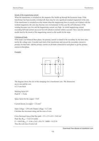


![Download free ebooks at bookboon.com
Electrical Power
138
Rectifiers
V1 to V6 are six phases spaced at 600
between phases.
Average DC output voltage = shaded area divided by (ʌ / 6)
V = (6/ʌ) œ Vp Cos șdș from 0 to ʌ/6
= (6/ʌ) Vp Sin ș from 0 to ʌ/6
= (6/ʌ) Vp [Sin ʌ/6 – Sin 0 ]
= (6/ʌ) Vp (1/2)
= 3 Vp /ʌ = 0.955 Vp
where Vp is the maximum phase voltage of the six phase supply
Three phase rectification of phase voltages
Supply from 3 phase voltages spaced 2ʌ/3
Average DC voltage
V =(3/ʌ) œ Vp Cos șdș from 0 to ʌ/3
= (3/ʌ) Vp Sin ș from 0 to ʌ/3
= (3/ʌ) Vp [Sin ʌ/3 – Sin 0 ]
= (3/ʌ) Vp ¥3 /2 = 0.827 Vp
where Vp is the maximum phase voltage of the three phase supply](https://image.slidesharecdn.com/electrical-power-221021180938-fb4e1a70/85/electrical-power-pdf-138-320.jpg)


![Download free ebooks at bookboon.com
Electrical Power
141
Rectifiers
In the diagram, V is the voltage across the capacitance.
Assume the capacitance is large enough for V to be considered constant.
The current flowing from the supply between ș1 and ș2 is
i = [Vp Sin ș – V] / R
The total quantity of electricity flowing from the supply in one cycle is proportional to the shaded area.
Q = œ[Vp Sin ș – V] / R dș
But this is the same as the total quantity of electricity flowing in the load in one complete cycle
= IDC 2ʌ where IDC is the DC load current.
IDC 2 ʌ = [ – Vp Cos ș – V ș ] / R from ș1 to ș2
= 2 [– Vp Cos ș – V ș ] / R from ș1 to ʌ / 2
= 2 [– Vp Cos (ʌ / 2) – V (ʌ / 2) + Vp Cos ș1 + V ș1 ] / R
= 2 [– V(ʌ / 2 – ș1) + Vp Cos ș1] / R
But Vp Sin ș1= V
Vp Cos ș1 – Vp Sin ș1 (ʌ / 2 – ș1) = ʌRIDC
Hence ș1 can be evaluated and hence V = Vp Sin ș1
Capacitance in DC output from a multi phase rectifier
Let the supply have Z phases
Then in one cycle, current input = Z times current input of each phase
Other parameters being equal, DC current per phase= IDC / Z
where IDC is the total DC current.
Hence Vp Cos ș1 – Vp Sin ș1 (ʌ / 2 – ș1) = ʌR IDC /Z
Evaluate ș1 and put V = Vp Sin ș1
For example
CLS
INPUT “Enter the RMS value of the supply “; Vrms
INPUT “Enter number of phases in the supply “; Z
INPUT “Enter the series resistance “; R
INPUT “Enter the average DC current “; Idc
Vp = SQR(2) * Vrms
Xmin = 0 : Xmax = 3.14159/2 : S = 0.1
100 ‘
Flag = 0
FOR X = Xmin TO X max STEP S
E = (Vp * COS(X) – Vp * SIN(X)*(3.14159/2 – X)) – (3.14159*R*Idc / Z)](https://image.slidesharecdn.com/electrical-power-221021180938-fb4e1a70/85/electrical-power-pdf-141-320.jpg)


![Download free ebooks at bookboon.com
Electrical Power
161
Instruments
It can be seen that ĭ1 and I2 exert an anti-clockwise torque on the drum while ĭ2 and ĭ1 exert a clockwise
torque. The drum does not rotate when ĭ1 and ĭ2 are in phase.
The torque due to I1 is proportional to I1 rms ĭ2 rms Cos Į where
Į is the phase angle between I1 and ĭ2 due to the leakage flux.
Consider now if ĭ1 and ĭ2 are not in phase. Let ĭ1 lead ĭ2 by ȕ.
The torques are proportional to
ĭ1 rms I2 rms Cos (Į + ȕ)
and ĭ2 rms I1 rms Cos (ȕ - Į) and are no longer equal.
The magnetising forces exert a torque on the drum proportional to
ĭ2 rms I1 rms Cos (ȕ - Į) - ĭ1 rms I2 rms Cos (Į + ȕ)
If ĭ1 rms = ĭ2 rms then I1 rms = I2 rms and
Torque = K ĭrms Irms [Cos (ȕ - Į) - Cos (Į + ȕ)]
= K ĭrms Irms Sin Į Sin ȕ
Disc Induction Meter
If the drum is rolled out flat, it becomes a disc. The disc will rotate if subjected to the interlinking flux of
two coils carrying AC currents which are not in phase.
The two coils can be supplied from the same source if one is supplied through a resistance or capacitance.
Alternatively, one of the poles could be a “shaded pole”, ie be fitted with a thick copper band.](https://image.slidesharecdn.com/electrical-power-221021180938-fb4e1a70/85/electrical-power-pdf-161-320.jpg)
![Download free ebooks at bookboon.com
Electrical Power
162
Instruments
Watt Hour Induction Meter
The Watt Hour meter has one coil connected to the voltage
and the current in this coil lags the voltage by 900
. The other
coil is connected to carry the current.
Thus ȕ = 900
– ij and Sin ȕ = Cos ij
The torque is proportional to V I Cos ij = watts
A permanent magnet is fitted round the disc. This causes an eddy current loss proportional to (speed) 2
.
This loss exerts a braking torque
The braking torque x speed = loss
braking torque = K (speed)2
/(speed
= K speed.
But the driving torque = braking torque
Thus speed is proportional to watts
Hence the number of rotations is proportional to watt hours
Example
An induction meter has a copper disc. The disc is changed to an aluminium disc of the same size. The
speed is to be increased by 50% for the same torque. Find the change in restraining magnet strength.
Specific resistance of aluminium = 1.7 x specific resistance of copper
Eddy current loss is ` n2
Bmax
2
t2
/ ȡ
Torque = power/speed ` n Bmax
2
t2
/ ȡ
With suffix 2 for new value and suffix 1 for old
n1 Bmax1
2
t1
2
/ ȡ1 = n2 Bmax2
2
t2
2
/ ȡ2
Bmax2 / Bmax1 = (t1/t2) ¥[(n1/n2) (ȡ2/ȡ1)] = ¥[(1/1.5) (1.7/1)] = 1.06
B must be increased by 6%
Fluxmeter
A DC fluxmeter is a moving coil meter without a spring connected to a search coil. When the flux through
the coil is changed, a current flows through the meter which is restrained only by its own back emf e.
Meter coil has n turns, area A, flux density B and carries a current i
Search coil has N turns and the flux is ĭ, circuit resistance R and inductance L
Torque on meter coil T = i n A B
Back emf e = n A B dș /dt where ș is the deflection.](https://image.slidesharecdn.com/electrical-power-221021180938-fb4e1a70/85/electrical-power-pdf-162-320.jpg)


![Download free ebooks at bookboon.com
Electrical Power
179
Generator Response to System Faults
Parameters are given the suffix 0 to indicate their value at time t=0. The total emf and flux (hence ampere
turns) on each axis do not change immediately when the fault occurs. Therefore E0 = EL, Eq0 = EqL, Ed0
= EdL and the total mmf on each axis is initially unchanged.
On the diagram;
Sin = Eq0 / E0 and Ed0 = E0 Cos
Resolving horizontally and vertically;
Iq0 x R + Id0 x ( X + Xd”) = Ed0
Id0 x R = Eq0 + Iq0 x (X + Xq”)
Therefore
Id0 = [ Eq0 R + Ed0 ( X + Xq”)] / [ R2
+ (X + Xd”) ( X + Xq” ) ]
Iq0 = [Ed0 R – Eq0 (X + Xd”) ] / [ R2
+ (X + Xd”) ( X + Xq” ) ]
Put c1 = (X + Xq”) / [ R2
+ (X + Xd”) ( X + Xq” ) ]
c2 = c1 R / (X + Xq”)
c3 = c1 (X + Xd”) / (X + Xq”)
Then Id0 = c1 Ed0 + c2 Eq0
And Iq0 = c2 Ed0 – c3 Eq0
These relationships also apply with suffix t since R and X are unchanged.
Hence the values of I0 and V0 can be calculated.
I0 = ¥( Id02
+ Iq02
)
V0 = I0 x ¥ ( R2
+ X2
)
Let the transient direct axis components of the fault current be I” decaying with time constant Td” and I’
decaying with time constant Td’.
The ampere turns are not initially changed, hence
I” + I’ = Id0 – IdL
The initial currents induced in the damping winding and the main field winding are determined by the flux
linkage and the impedance of the circuits. Thus the ratio of these induced currents is always the same.
It will be assumed that the ratio I” / I’ is also the same for all faults.
On short circuit; I” = ( I’ + I”) * (1/Xd” – 1/Xd’) / (1/Xd” – 1/Xd).
and I’ = ( I’ + I”) * (1/Xd’ – 1/Xd) / (1/Xd” – 1/Xd).
Hence I” = (Id0 – IdL) x (1/Xd” – 1/Xd’) / (1/Xd” – 1/Xd).
and I’ = (Id0 – IdL) x (1/Xd’ – 1/Xd) / (1/Xd” – 1/Xd).
Let F0 be the field current that would give the same ampere turns as the net ampere turns on the direct axis.
F0 x Nf = IfL Nf + [ I” exp(- t/Td”) + I’ exp(-t/Td’) – Id0] Na
where Na / Nf = (Xd – Xd”)/M1
F0 = If0 + [I” exp(- t/Td”) + I’ exp(-t/Td’) – Id0] (Xd – Xd”)/M1](https://image.slidesharecdn.com/electrical-power-221021180938-fb4e1a70/85/electrical-power-pdf-179-320.jpg)
![Download free ebooks at bookboon.com
Electrical Power
180
Generator Response to System Faults
Initially, the ampere turns are unchanged hence F0 = FL and If0 = IfL
The net ampere turns on the quadrature axis are;
Iq0 N – (Iq0 – IqL) N exp (-t/Tq”)
Values of the parameters during the fault t seconds after the start of the fault
The suffix t indicates the value during the fault at t seconds after the incidence of the fault and the vector
diagram becomes;
The time constants Td”, Td’ and Tq” will have values between the short circuit and open circuit values.
Field current on the direct axis that would produce the same ampere turns;
Fet = Ft + [I” exp(- t/Td”) + I’ exp(-t/Td’) – Idt] N
Put c4 = Ft + [I” exp(- t/Td”) + I’ exp(-t/Td’) N
Where N = (Xd – Xd”)/M1
On the Direct axis;
Et = U + M c4 – M Idt N
= U + M c4 – M Idt (Xd – Xd”)/M1
Put c5 = U + M c4
and c6 = M (Xd – Xd”)/M1
Then Et = c5 – c6 Idt](https://image.slidesharecdn.com/electrical-power-221021180938-fb4e1a70/85/electrical-power-pdf-180-320.jpg)
![Download free ebooks at bookboon.com
Electrical Power
181
Generator Response to System Faults
On the Quad axis;
Eqt = (Xq – Xq”) [Iqt – (Iq0 – IqL) exp(-t/Tq”)]
Put c7 = (X - Xq”)
and c8 = c7 (Iq0 – IqL) exp(-t/Tq”)
Then Eqt = c7 Iqt – c8
But Iqt = c2 Edt – c3 Eqt
Eqt = c7 c2 Edt - c7 c3 Eqt - c8
Put c9 = c7 c2 /(1 + c7 c3)
and c10 = c8 / (1 + c7 c3)
Then Eqt = c9 Edt – c10
But Et = c5 – c6 Idt
and Idt = c1 Edt + c2 Eqt
Thus Et = c5 – c6 c1 Edt – c6 c2 Eqt
= c5 – c6 c1 Edt – c6 c2 c9 Edt + c6 c2 c10
= c5 + c6 c2 c10 – (c6 c1 + c6 c2 c9 ) Edt
Put c13 = c6 c1 + c6 c2 c9
and c14 = c5 + c6 c2 c10
Then Et = c14 - c13 Edt
Do you want your Dream Job?
More customers get their dream job by using RedStarResume than
any other resume service.
RedStarResume can help you with your job application and CV.
Go to: Redstarresume.com
Use code “BOOKBOON” and save up to $15
(enter the discount code in the “Discount Code Box”)
Please
click
the
advert](https://image.slidesharecdn.com/electrical-power-221021180938-fb4e1a70/85/electrical-power-pdf-181-320.jpg)
![Download free ebooks at bookboon.com
Electrical Power
182
Generator Response to System Faults
But Et2
= Edt2
+ Eqt2
Substitute to get a quadratic in Edt
[c14 - c13 Edt] 2
= Edt2
+ [c9 Edt – c10] 2
Put c15 = 1 + c92
– c132
and c16 = 2 c14 c13 – 2 c9 c10
and c17 = c102
– c142
Finally Edt =[ – c16 + ¥( c162
– 4 c15 c17)] / (2 c15)
Hence Eqt = c9 Edt – c10
and Et = ¥( Edt2
+ Eqt2
)
and Iqt = c2 Edt – c3 Eqt
and Idt = c2 Eqt + c1 Edt
and It = ¥( Idt2
+ Iqt2
)
and Vt = It / ¥( R2
+ X2
)
Effect of the quadrature axis fault current on the time constant Tq”
Consider the effect of the induced current in the damping winding on the quadrature axis.
- Nk dĭq/dt = Lk dik/dt + Rk ik
Also ĭq = Mk Nk ik - Mk Na Iq
Where Mk is the relation between ampere turns and ĭq on the quadrature axis. The ampere turns of the
armature current oppose the induced ampere turns in the damping winding, hence the negative sign.
But Eq is proportional to the flux and speed of rotation
Let Eq = K ĭq
Iq = [Eq / (Z + Xa )] Sin T = K ĭq Sin T /(Z + Xa )
Therefore;
ĭq [1 + Mk Na K Sin T / (Z + Xa )] = Mk Nk ik
Put Mka = Mk / [1 + Mk Na K Sin T / (Z + Xa )]
ĭq = Mka Nk ik
Hence dĭq/dt = Mka Nk dik /dt
– Nk Mka Nk dik /dt = Lk dik/dt + Rk ik
[Nk Mka Nk + Lk ] dik/dt + Rk ik = 0
multiply by the integrating factor exp[Rk /(Nk Mka Nk + Lk)] t](https://image.slidesharecdn.com/electrical-power-221021180938-fb4e1a70/85/electrical-power-pdf-182-320.jpg)
![Download free ebooks at bookboon.com
Electrical Power
183
Generator Response to System Faults
put Tqk = (Nk Mka Nk + Lk) / Rk
d/dt [ik exp(t/Tqk)] = 0
Integrating ik exp(t/Tqk) = C
Thus ik = ik0 exp(– t/Tqk)
Where ik0 is the value of ik at t = 0
And ĭq = ĭq0 exp(– t/Tqk)
Where ĭq0 is the value of ĭq at t = 0
The armature current Iq is proportional to the emf Eq which is proportional to the flux ĭq and therefore Iq
decays with the same time constant as the flux.
Hence Tq” = Tqk = (Nk Mka Nk + Lk) / Rk
Put T1 = Nk Mk Nk / Rk and T2 = Lk / Rk
T1 and T2 are constants fixed by the physical dimensions of the machine.
T2 is the time constant of the damping winding due to the resistance and leakage reactance while T1 is the
time constant due to the same resistance and the reactance including flux linkage with the magnetic circuit.
Thus T1 T2
Tq” = T1 Mka/ Mk + T2 = approximately T1 Mka/ Mk
But Mka / Mk = 1/ [1 + Mk Na K Sin T / (Z + Xa )]
Where Mk , Na and K are constants fixed by the dimensions of the machine.
Put Mka / Mk = 1/ [1 + D Sin T / (Z + Xa )]
Where D is a constant fixed by the physical dimensions of the machine.
Tq” = T1 / [1 + D Sin T / (Z + Xa )]
When Z is very large, Tq” = Tqo” therefore T1 = Tqo”
Therefore Tq” œ Tqo” / [1 + D Sin T / (Z + Xa ) ]
When Z = 0, Tq” = Tqs” and Sin T = 1
Thus Tqs” = Tqo” / [1 + D / Xa ]
D =[ Tqo” - Tqs”] Xa / Tqs”
Tq” = Tqo” / [1 + (Tqo” - Tqs”) Xa / Tqs” Sin T / (Z + Xa ) ]
= Tqo” Tqs”/ [Tqs” + (Tqo” - Tqs”) Xa / (Z + Xa ) Sin T ]
where Z and Sin T are the values applicable to the fault
Hence, putting Xq” for the leakage reactance and Iq0/I0 for Sin T
Tq” = Tqo” Tqs”/ [Tqs” + (Tqo” – Tqs”) Xq” / (Z + Xq” ) (Iq0/I0) ]
Effect of the direct axis fault current on the time constants Td” and Td’
Consider the effect of the induced currents in the damping winding and the main field winding on the
direct axis.
– Nk d(ĭd)/dt = Lk dik/dt + Rk ik
– Nf d(ĭd)/dt = Lf dif/dt + Rf if](https://image.slidesharecdn.com/electrical-power-221021180938-fb4e1a70/85/electrical-power-pdf-183-320.jpg)

![Download free ebooks at bookboon.com
Electrical Power
185
Generator Response to System Faults
Then ĭd Nf = U + M [Nk ik + Nf if – Na iad]
But Ed is proportional to the flux and the speed of rotation
Let Ed = K ĭd
Id = [Ed / (Z + Xa )] Cos T = K ĭd Cos T /(Z + Xa )
Therefore;
ĭd Nf [1 + M (Na /Nf ) K Cos T / (Z + Xa )] = U + M [Nk ik + Nf if]
Put Ua = U / [1 + M (Na /Nf ) K Cos T / (Z + Xa )]
and Ma = M / [1 + M (Na /Nf ) K Cos T / (Z + Xa )]
ĭd Nf = Ua + Ma (Nk ik + Nf if)
Thus the effect of armature reaction on the direct axis is to reduce the flux by an amount that is
proportional to the reduction in Ma. But the reduction in Ma reduces the time constants from the open
circuit value towards the short circuit value by an amount proportional to the direct axis component of the
armature current. The armature current is approximately inversely proportional to the impedance Z + Xa .
The effect is similar to the effect on the quadrature axis. Hence, putting Xd” for the leakage reactance Xa
and Id0/I0 for Cos T.
Td” = Tdo” Tds”/[ Tds” + (Tdo” – Tds”) Xd“ / (Z + Xd”) (Id0/I0)]
Td’ = Tdo’ Tds’/[ Tds’ + (Tdo’ – Tds’) Xd’ / (Z + Xd’) (Id0/I0)]
Summary of Ampere Turns on each axis
Direct Axis
Event Exciter Armature Induced mmf Total
On Load Fel =
Fe + N*IdL
- N*IdL 0 Fe
t = 0
during the fault
FeL =
Fe + N*IdL
- N*Id0 N * (Id0 – IdL)
= N*( I1+I2)
Fe
Time t during
the fault
FeL =
Fe + N*IdL
- N*Idt N* [I1*exp(-t/Td1)
+ I2*exp(-t/Td2)]
Ft
s = 0 after
clearance
FeL =
Fe + N*IdL
- N*IdC N*(I1C+I2C) Ft
Time s after
clearance
FeL =
Fe + N*IdL
- N*Ids N*[I1C*exp(-s/Td1C)
+I2C*exp(-s/Td2C)]
Fs
On this table, the excitation is assumed constant
Fe is the excitation to give open circuit full volts
Add horizontal lines to get the total;](https://image.slidesharecdn.com/electrical-power-221021180938-fb4e1a70/85/electrical-power-pdf-185-320.jpg)
![Download free ebooks at bookboon.com
Electrical Power
186
Generator Response to System Faults
I1 + I2 = Id0 – IdL
Ft = Fe + N*IdL – N*Idt + N*(I1*exp(-t/Td1)+I2*exp(-t/Td2))
I1C +I2C = [Ft – Fe – N*IdL + N*IdC] / N
Fs = Fe + N*IdL – N*Ids + N*I1C*exp(-s/Td1C) + N*I2C*exp(-s/Td2C)
Quadrature axis
Event Armature Induced mmf Total
On Load N * IqL 0 N * IqL
t = 0
during the fault
N * Iq0 N*(IqL-Iq0)
= - N * I3
N * IqL
Time t during
the fault
N * Iqt - N * I3*exp(-t/Tq2) N*
[Iqt-I3*exp(-t/Tq2)]
S = 0 after
clearance
N * IqC N*[Iqt – IqC
- I3*exp(-t/Tq2)]
= - N * I3C
N*
[Iqt-I3*exp(-t/Tq2)]
Time s after
clearance
N * Iqs - N * I3C *exp(-s/Tq2C) N * [Iqs
- I3C *exp(-s/Tq2C)]
I3 = Iq0 – IqL
I3C = I3*exp(-t/Tq2) – Iqt + IqC
Exciter response
The main field current due to the pilot exciter has been assumed to be constant during the fault. It
therefore has played no part in the changing flux. In practice however the exciter current does change
rapidly under the control of the Automatic Voltage Regulator. While the voltage Vt remains below the
reference voltage, the pilot exciter, and hence the main exciter will be boosting at their maximum rate.
The exciter response when boosting is;
Ef = Efmax – (Efmax – Ef0) Exp(-t/Te)
Where Te is the time constant of the combination of exciter and pilot exciter.
This is applied to the main field winding, resistance Rf and inductance Lf.
Let the time constant of this winding be Td.
Td = Lf /Rf
Ef = Lf dif / dt + R if](https://image.slidesharecdn.com/electrical-power-221021180938-fb4e1a70/85/electrical-power-pdf-186-320.jpg)
![Download free ebooks at bookboon.com
Electrical Power
187
Generator Response to System Faults
Multiply by the integrating factor Exp(t/Td)
Lf d/dt [ if Exp(t/Td)] = Ef Exp(t/Td)
= Efmax Exp(t/Td) – (Efmax – Ef0) Exp[t (1/Td – 1/Te)]
Integrate;
Lf [ if Exp(t/Td)] = Efmax Td Exp(t/Td)
– (Efmax – Ef0) / (1/Td – 1/Te) Exp[t (1/Td – 1/Te)] + C
if = Efmax Td / Lf - (Efmax – Ef0) / (1/Td – 1/Te) / Lf Exp(–t/Te)
+ C Exp(–t/Td)
if = Efmax /Rf – (Efmax – Ef0) /Rf / (1 – Td/Te) Exp(–t/Te) + C Exp(–t/Td)
But Efmax /Rf =Ifmax and Ef0/Rf = If0
if = Ifmax – (Ifmax – If0) Te / (Te – Td) Exp(–t/Te) + C Exp(–t/Td)
When t = 0, if = if0
Therefore C = if0 – Ifmax + (Ifmax – If0) Te / (Te – Td)
= (Ifmax – If0) Td / (Te – Td)
if = Ifmax – (Ifmax – If0) / (Te – Td) [Te Exp(–t/Te) – Td Exp(–t/Td)]
But in fact there are two time constants Td’ and Td”. The effect of each can be apportioned by the factors
I’/(I’ + I”) and I” / (I’ + I”)
NNE and Pharmaplan have joined forces to create
NNE Pharmaplan, the world’s leading engineering
and consultancy company focused entirely on the
pharma and biotech industries.
Inés Aréizaga Esteva (Spain), 25 years old
Education: Chemical Engineer
NNE Pharmaplan is the world’s leading engineering and consultancy company
focused entirely on the pharma and biotech industries. We employ more than
1500 people worldwide and offer global reach and local knowledge along with
our all-encompassing list of services. nnepharmaplan.com
– You have to be proactive and open-minded as a
newcomer and make it clear to your colleagues what
you are able to cope. The pharmaceutical field is new
to me. But busy as they are, most of my colleagues
find the time to teach me, and they also trust me.
Even though it was a bit hard at first, I can feel over
time that I am beginning to be taken seriously and
that my contribution is appreciated.
Trust and responsibility
Please
click
the
advert](https://image.slidesharecdn.com/electrical-power-221021180938-fb4e1a70/85/electrical-power-pdf-187-320.jpg)
![Download free ebooks at bookboon.com
Electrical Power
188
Generator Response to System Faults
A problem occurs if Td equals Te as coefficients in the equation for if become infinitely large.
Let 1/Td = 1/Te + d and take the limit as d tends to zero.
Td = Te – Td Te d
Exp(–t/Td) = Exp[–t (1/Te + d) = Exp(–t/Te) Exp(–t d)
= Exp(–t/Te) (1 – (t d) + (t d)2
/2 + higher powers of d
if = Ifmax – (Ifmax – If0) / (Te – Td) [Te Exp(–t/Te) – Td Exp(–t/Td)]
= Ifmax – (Ifmax – If0) /(TeTdd) Exp(–t/Te)
[Te – (Te – Td Te d) (1 – (t d) + (t d)2
/2)]
= Ifmax – (Ifmax – If0) (t/Td + 1) Exp(–t/Te) + higher powers of d
Limit if as d approaches zero
if = = Ifmax – (Ifmax – If0) (t/Td + 1) Exp(–t/Te)
If the voltage recovers to the reference voltage then the AVR no longer calls for an increase in excitation.
All the parameters need to be recalculated on the basis of the busbar voltage being equal to the AVR
reference voltage, ie the rated value plus or minus the compounding.
Step by step evaluation of the fault current
The following information is needed;
Generator size MVA and MW and voltage kV
Generator reactances Xd, Xd”, Xd’, Xq, Xq”, Xneg, X zero
Generator time constants Tds”, Tds’, Tqs”, Tdo”, Tdo’, Tqo”
Generator open circuit curve m1, U2, m2, U3, m3, U4, m4
Maximum and minimum exciter voltage as per unit of value for OC full volts
Generator compounding voltage on full load as % system volts
Generator compounding voltage phase angle
Generator governor droop as % speed change no load to full load
Generator inertia H in kW seconds per kVA at rated speed
Full load expressed as system resistance RL and reactance XL
Fault impedance to power station busbars as RF and XF
Lines beginning with * are for information and are not part of the step by step procedure.
A = RL/ ZL2
+ RF / ZF2
B = XL / ZL2
+ XF / ZF2
R = A / (A2
+ B2
)
X = B / (A2
+ B2
)](https://image.slidesharecdn.com/electrical-power-221021180938-fb4e1a70/85/electrical-power-pdf-188-320.jpg)
![Download free ebooks at bookboon.com
Electrical Power
189
Generator Response to System Faults
Tan TL = RL/(Xq + XL)
IL = V / ¥ [RL2
+ XL2
]
IdL = IL Cos TL
IqL = IL Sin TL
EqL = IqL (Xq – Xq”)
EL = ¥ [ {IqL RL + IdL (XL + Xd”)}2
+ EqL2
]
IfL = (EL – U2) / M2 + IdL (Xd – Xd”) / M1
Sin = EqL / EL
Cos = ¥ (1 – Sin2
)
Eq0 = EqL
Ed0 = EdL
E0 = EL
If0 = IfL
c1 = (X + Xq”) / [ R2
+ (X + Xd”) ( X + Xq” ) ]
c2 = c1 R / (X + Xq”)
c3 = c1 (X + Xd”) / (X + Xq”)
Id0 = c2 Eq0 + c1 Ed0
Iq0 = c2 Ed0 – c3 Eq0
I0 = ¥ [Id02
+ Iq02
]
Z = ¥ [R2
+ X2
]
V0 = I0 Z
Td” = Tdo” Tds”/[ Tds”+ (Tdo” – Tds”) (Id0/I0) Xd“ / ¥{R2
+ (X + Xd”) 2
}]
Td’ = Tdo’ Tds’/[ Tds’+ (Tdo’ – Tds’) (Id0/I0) Xd’ / ¥{R2
+ (X + Xd’) 2
}]
Tq” = Tqo” Tqs”/[ Tqs”+ (Tqo” – Tqs”) (Iq0/I0) Xq“ / ¥{R2
+ (X + Xq”) 2
}]
I” = (Id0 – IdL) (1/Xd” – 1/Xd’) / (1/Xd” – 1/Xd)
I’ = (Id0 – IdL) (1/Xd’ – 1/Xd) / (1/Xd” – 1/Xd)
Choose a value for t
Ift = Ifmax - (Ifmax – IfL) exp(-t/Te) provided the voltage has not recovered.
Lines beginning with * are for information, not in the step by step evaluation.
c4 = Ift + [I’ exp(-t/Td’) + I” exp(-t/Td”)] (Xd – Xd”)/M1
c5 = freqt/freq (U + m c4)
c6 = freqt/freq (Xd – Xd”) / M1
* Then Et = U + M (c5 – c6 Idt ) corrected for speed change
c7 = freqt/freq (Xq – Xq”)
c8 = c7 (Iq0 – IqL) exp(-t/Tq”)
* then Eqt = c7 Iqt – c8 corrected for speed change
* but Iqt = c2 Edt – c3 Eqt
* substitute for Iqt to get Eqt = c9 Edt – c10, where;
c9 = c7 c2 / (1 + c7 c3)
c10 = c8 / (1 + c7 c3)
* also Et = U + M (c5 – c6 Idt )
* and Idt = c2 Eqt + c1 Edt](https://image.slidesharecdn.com/electrical-power-221021180938-fb4e1a70/85/electrical-power-pdf-189-320.jpg)
![Download free ebooks at bookboon.com
Electrical Power
190
Generator Response to System Faults
* substitute for Idt and Eqt to get Et = c14 – c13 Edt, where;
c13 = c6 c2 c9 + c6 c1
c14 = c5 + c6 c2 c10
* but Et2
= Eqt2
+ Edt2
* substituting for Et and Eqt gives a quadratic in Edt
* c15 Edt2
– c16 Edt + c17 = 0, where;
c15 = 1 + c92
– c132
c16 = 2 c14 c13 – 2 c9 c10
c17 = c102
- c142
* hence;
Edt = [– c16 + ¥(c162
– 4 c15 c17)]/(2 c15)
Eqt = c9 Edt – c10
Et2
= ¥[Eqt2
+ Edt2
]
Iqt = c2 Edt – c3 Eqt
Idt = c2 Eqt + c1 Edt
It2
= ¥[Iqt2
+ Idt2
]
Vt = It ¥[R2
+ X2
]
These equations evaluate the emfs, the fault current and power station busbar voltage at any time t seconds
after the fault occurs.
If the exciter can restore the voltage to normal volts before the fault is cleared, then the AVR will cease to
call for an increase in the field current.
The frequency at time t seconds after the fault occurs is found by calculating the combined load of
resistance R and reactance X in steps during the fault. The difference between this load and the system
load before the fault means the generators will slow down or speed up under the control of the governors.
In most cases, the generators will speed up as the fall in voltage reduces the load while the fault current is
low power factor and contributes little to the load. The change in speed that actually occurs depends on the
inertia of the machine.](https://image.slidesharecdn.com/electrical-power-221021180938-fb4e1a70/85/electrical-power-pdf-190-320.jpg)


![Download free ebooks at bookboon.com
Electrical Power
195
Calculation of Faults Currents
The Zero sequence impedance/phase Z0 is then 3 x Volts / Current.
The Zero sequence resistance R0 is 3 x Watts/(Current)2
The Zero sequence reactance is X0 is ¥(Z0
2
- R0
2
)
It may be necessary to correct for the voltage drop across the ammeter and wattmeter current coil or for
the current through the voltmeter and wattmeter voltage coil.
Calculation of Fault Currents
Where a power system contains transformers, impedances in series at different voltages cannot be simply
added. They must all be converted to the equivalent at the same voltage.
A convenient way to do this is to evaluate each impedance as the per cent volt drop when carrying a “base
load”. The base load can be any value but it is common to use 10 MVA.
Impedances to a base 10 MVA
The impedance Z to base 10 MVA is given by;
Z = (% Plant Impedance) 10 / (Plant MVA)
Z = 1000 (Impedance in ohms per phase) / (line kV)2
Impedances in series and at different voltages each expressed to a common base 10 MVA can be a added
numerically, ie R = R1 + R2 and X = X1 + X2.
Fault MVA
Fault MVA = [1000 /(total % impedance including the generator subtransient
reactance to base 10 MVA)] MVA
Short Circuit heating
Temp rise in degrees C = [Aps/mm2
]2
x (time in seconds) / (material factor)
where the material factor is about 700 for copper and about 300 for aluminium.
For the permissable short circuit heating, see BS7671 para 434.5.2.](https://image.slidesharecdn.com/electrical-power-221021180938-fb4e1a70/85/electrical-power-pdf-195-320.jpg)


![Download free ebooks at bookboon.com
Electrical Power
199
Symetrical Components
Line to line and ground fault (LLG)
Ia = 0, Vb = Vc = 0
Substituting and simplifying;
I1 = E /( Z1 + Z0 Z2 /(Z0 + Z2))
I2 = – I1 Z0 /( Z0 + Z2)
I0 = – I1 Z2 /( Z0 + Z2)
Ib = I0 + h2
I1 + h I2
Ic = I0 + h I1 + h2
I2
Current to ground = 3 I0
For fault calculations, it is best to calculate the symmetrical components and then add them vectorally to
obtain Ib and Ic. The current to ground, which will be needed if there is earth fault protection, is three
times the zero sequence component.
Using these values for the fault calculations, the positive sequence current and the positive sequence
busbar voltage are obtained.
Power in terms of symmetrical components
Power due to I1 is the sum of the vector dot products;
W = E I1 + h 2
E h2
I1 + h E h I1
= E I1 Cos(I 1) +E I1 Cos(I 1) + E I1 Cos(I 1)
= 83 (line kV) I1 Cos(I 1)
Power due to I2 is the sum of the vector dot products;
W = E I2 + h 2
E h I2 + h E h 2
I2
= E I2 Cos(I 2) + E I2 Cos (2xS/3 +I 2) + E I2 Cos (2S/3 -I 2)
= E I2 [ Cos(I 2) – (1/2) Cos(I 2) – (83/2 ) Sin(I 2) – (1/2) Cos(I 2) + (83/2) Sin(I 2) ]
= 0
Power due to I0 is the sum of the vector dot products;
W = E I0+ h 2
E I0+ h E I0 = 0
Thus the total power due to the symmetrical components is;
W = 83 (line kV) I1 Cos(I 1)
where W is in MW, I1 is in kiloamps and I 1 is the phase angle of I1](https://image.slidesharecdn.com/electrical-power-221021180938-fb4e1a70/85/electrical-power-pdf-199-320.jpg)


![Download free ebooks at bookboon.com
Electrical Power
202
Symetrical Components
Double Line to ground fault involves the vector sum and difference between the currents on each phase.
Thus it is best to keep the fault currents in terms of the symmetrical components until final evaluation.
Combination of Fault current and Load current
LLL and LLLG Faults
The Fault current and Load current are both positive phase sequence only
Hence Total Current = vector sum of Fault current ifault and Load current iL
= /[{ifault cos (IF) + iL cos (IL)}2
+ {ifault sin (IF) + iL sin (IL)}2
]
where IF = arctan( XF/RF) and IL = arctan (XL/RL)
LG Fault
The Positive, Negative and Zero phase sequence currents are all in phase on the line with the fault. The
Fault current ifault is the sum of these currents.
Hence on the phase with the fault,
Total current = vector sum of ifault and iL
Hence Total Current
= /[ {ifault cos (IF) + iL cos (IL)}2
+ {ifault sin (IF) + iL sin (IL)}2
]
where IF = arctan( XF/RF) and IL = arctan (XL/RL)
On the other two phases, the fault current is zero.
LL Fault
Zero sequence component = 0
Assume the fault is between phases B and C
On phase A, the Fault current is zero.
On phase A, the Negative sequence component is equal and opposite to the Positive sequence component.](https://image.slidesharecdn.com/electrical-power-221021180938-fb4e1a70/85/electrical-power-pdf-202-320.jpg)
![Download free ebooks at bookboon.com
Electrical Power
203
Symetrical Components
On phase B,
Fault current = h2
Positive seq component + h Negative seq component
= (h2
- h) Positive seq component
Fault current = /3 x Positive sequence component of the Fault current
This current lags the voltage Eb by (IF - S/6)
On phase C,
Fault current is equal and opposite to the Fault current on phase B
It lags the voltage Ec by (IF + S/6)
Hence the Total current
= /[ {ifault cos (IT) + iL cos (IL)}2
+ {ifault sin (IT) + iL sin (IL)}2
]
where IF = arctan(XF/RF) and IL = arctan (XL/RL)
On phase B (IT) = (I F – S /6)
On phase C (IT) = (IF + S /6)
LLG Faults
The positive sequence component of the Fault Current can be obtained directly by putting;
XF = X1 + (R0
2
X2 + R2
2
X0 + X0 X2 (X0 + X2 ))
/((R0 + R2)2
+ (X0 + X2)2
)
RF = R1 + (R0 R2 (R0 + R2) + R2 X0
2
+ R0 X2
2
)
/((R0 + R2)2
+ (X0 + X2)2
)
6JGFGUKIPQHGEQHTKGPFN[OCTKPGRQYGTCPFRTQRWNUKQPUQNWVKQPUKUETWEKCNHQT/#0KGUGN6WTDQ
2QYGTEQORGVGPEKGUCTGQHHGTGFYKVJVJGYQTNFoUNCTIGUVGPIKPGRTQITCOOGsJCXKPIQWVRWVUURCPPKPI
HTQOVQM9RGTGPIKPG)GVWRHTQPV
(KPFQWVOQTGCVYYYOCPFKGUGNVWTDQEQO
.QYURGGF'PIKPGU/GFKWOURGGF'PIKPGU6WTDQEJCTIGTU2TQRGNNGTU2TQRWNUKQP2CEMCIGU2TKOG5GTX
The Wake
the only emission we want to leave behind
Please
click
the
advert](https://image.slidesharecdn.com/electrical-power-221021180938-fb4e1a70/85/electrical-power-pdf-203-320.jpg)
![Download free ebooks at bookboon.com
Electrical Power
204
Symetrical Components
This impedance can be combined with the Load Impedance to obtain the equivalent impedance R + jX
This enables the Total Positive sequence component to be obtained which can then be separated into the
Load Current and Positive Sequence Component of the Fault Current.
The Negative and Zero components of the Fault Current can then be obtained.
Let Positive Seq Component be Ipos at phase angle IPos
IPos = arctan(XF/RF)
Let Negative Seq Component be Ineg at phase angle INeg on phase A
Put R3 = R0 + R2 and X3 = X0 + X2
Ineg = - Ipos (R0 + j X0 ) / (R3 + j X3)
= - Ipos [ (R0 R3 + X0 X3 ) + j(R3 x X0 - R0 X3)] / (R3
2
+ X3
2
)
Hence magnitude of Ineg is given by
Ineg = - Ipos /[(R0 R3 + X0 X3 )2
+ (R3 X0 - R0 X3)2
] / (R3
2
+ X3
2
)
INeg = IF + arctan[ (R3 X0 - R0 X3) / (R0 R3 + X0 X3 ) ]
Interchange suffix 2 and 0 to get;
Magnitude of Izero is given by
Izero = - Ipos /[(R2 R3 + X2 X3 )2
+ (R3 X2 - R2 X3)2
] / (R3
2
+ X3
2
)
IZero = IF + arctan[ (R3 X2 - R2 X3) / (R2 R3 + X2 X3 ) ]
Thus the current in all phases with and without Load Current can be obtained by the vector addition of the
relevant currents.
Currents in phase B
Fault Current in phase B =
/[{Ipos Cos(IPos) + Ineg Cos(INeg – S/3) + Izero Cos(IZero +S/ 3)}2
+{Ipos Sin(IPos) + Ineg Sin(INeg – S/3) + Izero Sin(IZero +S/3)}2
]
Similarly, Fault Current in phase C =
/[{Ipos Cos(IPos) + Ineg Cos(INeg + S/3) + Izero Cos(IZero -S/3)}2
+{Ipos Sin(IPos) + Ineg Sin(INeg + S/3) + Izero Sin(IZero -S/3)}2
]
Current to ground = 3 Izero
For parts of the network carrying both Load Current and Fault Current,
put Ipos = ifault but keeping Ineg and Izero unchanged as these currents do not flow in the load circuit.](https://image.slidesharecdn.com/electrical-power-221021180938-fb4e1a70/85/electrical-power-pdf-204-320.jpg)


![Download free ebooks at bookboon.com
Electrical Power
208
Commissioning Electrical Plant
Fault Finding
High impedance faults
A high impedance fault on one phase of a long underground cable or overhead power line can be located
by a high voltage bridge.
Connect the remote end of the faulty core to a healthy core. Connect the high voltage bridge to this
healthy core and the faulty core. Supply the bridge from a high voltage test set and balance the bridge on
the slider. Note the readings R1 and R2.
Although the fault resistance may be several thousand ohms and the cable core only a few ohms, the ratio
[L1 + (L1 - L2)]/L2 is equal to R1/R2
Thus L2/L1 = 2 R2/(R1 + R2)
It is prudent to keep a record of the exact location of all cable joints on a long underground cable. The
fault is usually at a joint unless there is obvious damage above ground.
Maersk.com/Mitas
e Graduate Programme
for Engineers and Geoscientists
Month 16
I was a construction
supervisor in
the North Sea
advising and
helping foremen
solve problems
I was a
he
s
Real work
International opportunities
ree work placements
al
Internationa
or
ree wo
I wanted real responsibili
I joined MITAS because
Please
click
the
advert](https://image.slidesharecdn.com/electrical-power-221021180938-fb4e1a70/85/electrical-power-pdf-208-320.jpg)
![Download free ebooks at bookboon.com
Electrical Power
209
Program Manual
Program Manual
Getting Started
When the program is running, data is written to the source folder. Therefore the program will not run from
the CD. Copy and Paste the entire contents of the CD to your own Folder on your hard drive or onto a
floppy disc. In Windows, press the [Start] + [e] keys, click on the drive for the CD, for example “DVD-
RW Drive D”, click on “Edit”, click on “Copy”, click on your chosen destination Folder and click on
“Edit” and click on “Paste”.
Double click on the application program “Fault Calculations Rev 1.exe” and page 1 appears.
Click on Next and page 2 appears.](https://image.slidesharecdn.com/electrical-power-221021180938-fb4e1a70/85/electrical-power-pdf-209-320.jpg)


The document provides an overview of key concepts in electrical power engineering. It defines common units used to measure electrical quantities and properties of materials. It also summarizes fundamentals of DC circuits, magnetic fields, electromagnetism, AC circuits, electrical machines including motors and generators, and power systems components. The summary defines important terms concisely and establishes the scope of topics covered in the full document.