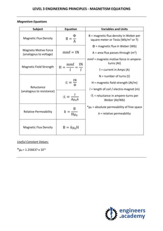
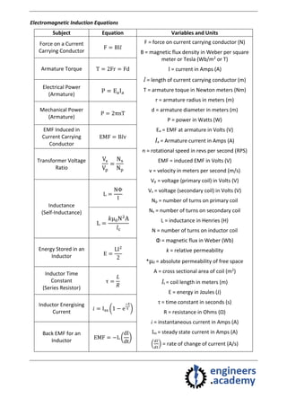
LEVEL 3 ENGINEERING PRINCIPLES - MAGNETISM EQUATIONS
Magnetism Equations
Subject Equation Variables and Units
Magnetic Flux Density B =
Φ
A
B = magnetic flux density in Weber per
square meter or Tesla (Wb/m2 or T)
Φ = magnetic flux in Weber (Wb)
A = area flux passes through (m2)
mmf = magneto motive force in ampere-
turns (At)
I = current in Amps (A)
N = number of turns (t)
H = magnetic field strength (At/m)
l = length of coil / electro-magnet (m)
R = reluctance in ampere-turns per
Weber (At/Wb)
*μ0 = absolute permeability of free space
k = relative permeability
Magneto Motive Force
(analogous to voltage)
mmf = IN
Magnetic Field Strength H =
mmf
𝑙
=
IN
𝑙
Reluctance
(analogous to resistance)
R =
IN
Φ
R =
𝑙
Aμ0 𝑘
Relative Permeability 𝑘 =
B
Hμ0
Magnetic Flux Density B = 𝑘μ0H
Useful Constant Values:
*μ0 = 1.256637 x 10⁻⁶
Electromagnetic Induction Equations
Subject Equation Variables and Units
Force on a Current
Carrying Conductor
F = BI𝑙
F = force on current carrying conductor (N)
B = magnetic flux density in Weber per square
meter or Tesla (Wb/m2 or T)
I = current in Amps (A)
l = length of current carrying conductor (m)
T = armature toque in Newton meters (Nm)
r = armature radius in meters (m)
d = armature diameter in meters (m)
P = power in Watts (W)
Ea = EMF at armature in Volts (V)
Ia = Armature current in Amps (A)
n = rotational speed in revs per second (RPS)
EMF = induced EMF in Volts (V)
v = velocity in meters per second (m/s)
Vp = voltage (primary coil) in Volts (V)
Vs = voltage (secondary coil) in Volts (V)
Np = number of turns on primary coil
Ns = number of turns on secondary coil
L = inductance in Henries (H)
N = number of turns on inductor coil
Φ = magnetic flux in Weber (Wb)
k = relative permeability
*μ0 = absolute permeability of free space
A = cross sectional area of coil (m2)
lc = coil length in meters (m)
E = energy in Joules (J)
τ = time constant in seconds (s)
R = resistance in Ohms (Ω)
i = instantaneous current in Amps (A)
Iss = steady state current in Amps (A)
(
𝑑𝐼
𝑑𝑡
) = rate of change of current (A/s)
Armature Torque T = 2Fr = Fd
Electrical Power
(Armature)
P = EaIa
Mechanical Power
(Armature)
P = 2πnT
EMF Induced in
Current Carrying
Conductor
EMF = B𝑙v
Transformer Voltage
Ratio
Vs
Vp
=
Ns
Np
Inductance
(Self-Inductance)
L =
NΦ
I
L =
𝑘μ0N2
A
𝑙c
Energy Stored in an
Inductor E =
LI2
2
Inductor Time
Constant
(Series Resistor)
τ =
𝐿
𝑅
Inductor Energising
Current
𝑖 = Iss (1 − e
−t
τ )
Back EMF for an
Inductor
EMF = −L (
dI
dt
)

Level 3 engineering principles magnetism equations

  • 1.
    LEVEL 3 ENGINEERINGPRINCIPLES - MAGNETISM EQUATIONS Magnetism Equations Subject Equation Variables and Units Magnetic Flux Density B = Φ A B = magnetic flux density in Weber per square meter or Tesla (Wb/m2 or T) Φ = magnetic flux in Weber (Wb) A = area flux passes through (m2) mmf = magneto motive force in ampere- turns (At) I = current in Amps (A) N = number of turns (t) H = magnetic field strength (At/m) l = length of coil / electro-magnet (m) R = reluctance in ampere-turns per Weber (At/Wb) *μ0 = absolute permeability of free space k = relative permeability Magneto Motive Force (analogous to voltage) mmf = IN Magnetic Field Strength H = mmf 𝑙 = IN 𝑙 Reluctance (analogous to resistance) R = IN Φ R = 𝑙 Aμ0 𝑘 Relative Permeability 𝑘 = B Hμ0 Magnetic Flux Density B = 𝑘μ0H Useful Constant Values: *μ0 = 1.256637 x 10⁻⁶
  • 2.
    Electromagnetic Induction Equations SubjectEquation Variables and Units Force on a Current Carrying Conductor F = BI𝑙 F = force on current carrying conductor (N) B = magnetic flux density in Weber per square meter or Tesla (Wb/m2 or T) I = current in Amps (A) l = length of current carrying conductor (m) T = armature toque in Newton meters (Nm) r = armature radius in meters (m) d = armature diameter in meters (m) P = power in Watts (W) Ea = EMF at armature in Volts (V) Ia = Armature current in Amps (A) n = rotational speed in revs per second (RPS) EMF = induced EMF in Volts (V) v = velocity in meters per second (m/s) Vp = voltage (primary coil) in Volts (V) Vs = voltage (secondary coil) in Volts (V) Np = number of turns on primary coil Ns = number of turns on secondary coil L = inductance in Henries (H) N = number of turns on inductor coil Φ = magnetic flux in Weber (Wb) k = relative permeability *μ0 = absolute permeability of free space A = cross sectional area of coil (m2) lc = coil length in meters (m) E = energy in Joules (J) τ = time constant in seconds (s) R = resistance in Ohms (Ω) i = instantaneous current in Amps (A) Iss = steady state current in Amps (A) ( 𝑑𝐼 𝑑𝑡 ) = rate of change of current (A/s) Armature Torque T = 2Fr = Fd Electrical Power (Armature) P = EaIa Mechanical Power (Armature) P = 2πnT EMF Induced in Current Carrying Conductor EMF = B𝑙v Transformer Voltage Ratio Vs Vp = Ns Np Inductance (Self-Inductance) L = NΦ I L = 𝑘μ0N2 A 𝑙c Energy Stored in an Inductor E = LI2 2 Inductor Time Constant (Series Resistor) τ = 𝐿 𝑅 Inductor Energising Current 𝑖 = Iss (1 − e −t τ ) Back EMF for an Inductor EMF = −L ( dI dt )