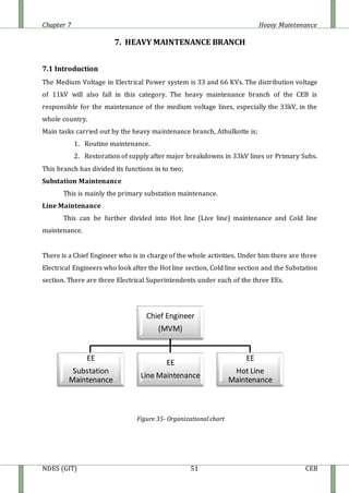
The document discusses heavy maintenance activities carried out by the CEB in Sri Lanka. It describes the organizational structure with a Chief Engineer overseeing three sections: hot line maintenance, cold line maintenance, and substation maintenance. Hot line maintenance involves inspecting and maintaining 33kV power lines while they are live. Cold line maintenance and substation maintenance involve maintenance when power is shut off. The document provides details on the types of distribution lines, tower identification, primary substations, transformers, circuit breakers, surge arrestors, isolators, auto-reclosers, and drop down lift off switches used in the electrical distribution system.
![Chapter 7 Heavy Maintenance
NDES (GIT) 62 CEB
can not be operated when the particular line is loaded. There is an inter lock system
between circuit breaker and isolator to ensure operators safety. Isolator can only be closed
when the particular line circuit breaker is in ‘off’ position and before isolator open,
particular line circuit breaker must be closed. Manufacturers of isolator give its nominal
current, nominal voltage, insulation level, etc.
Figure 42- Surge Arrestors Figure 43 – Isolators
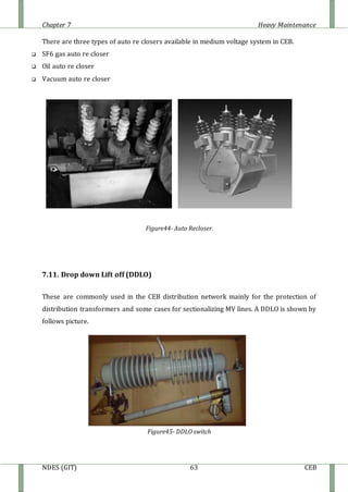
7.10. Auto Re closures
Auto re closers are self contaminated devises that make and break the distribution system
under normal at and fault conditions. A basic feature of a re closer is to re close
immediately once the circuit under which it served breaks due to temporary fault. Re closer
will lock out its operation whenever it senses a permanent fault clears before lock out, re
closer will reset for another cycle of operation.
Before CEB has introduced auto re closers to the distribution system, only DDLO’s are
provided as the protective devices.
But this needs some one to operate the DDLO in order to isolate the line from the power
supply. Therefore by introducing auto re closers to distribution system, the speed of fault
clearing has improved and hence which promotes the stability of the power system.
Because of these reasons the concepts of auto re closers entered as a time and money
saving method [the interruption period becomes less].
The minimum requirement for installing an auto re closer is 100 km 1 MVA. The re closers
are sensitive for over current, earth fault and in modern type’s sensitive earth faults too.](https://image.slidesharecdn.com/heavymaintenance-150509045956-lva1-app6892/85/Heavy-maintenance-12-320.jpg)