This document outlines various regulations and standards relating to the supply and use of electrical energy in India. It provides classifications for voltage levels and permissible voltage variations. It also specifies minimum clearances for overhead power lines based on voltage level, clearances between power lines that cross each other, and clearances from buildings and the ground. Various insulation and current carrying capacities for underground cables are also included.
Cable sizing to withstand short-circuit current - ExampleLeonardo ENERGY
A short circuit causes very extreme stresses in a cable which are proportional to the square of the current:
A temperature rise in the conducting components such as conductor, screen, metal sheath, armour. Indirectly the temperature of adjoining insulation and protective covers also increases,
electro-magnetic forces between the current-carrying components.
The temperature rise is important for its effect on ageing, heat pressure characteristics etc. and should be limited to a permissible short-circuit temperature. The thermo-mechanical effects of the current shall also be considered.
For the given short-circuit condition the short-circuit capacity of a cable should be investigated with respect to all these parameters. For multi-core cables in most instances the thermal effect - related to the magnitude of fault current and clearance time - is the critical parameter, since the cable will normally have enough mechanical strength. With single-core cables however the mechanical effect - related to the magnitude of the peak short-circuit current - is of such significance that, next to the thermal, the mechanical strength of both cable and its supports should be investigated.
Also accessories must be rated with respect to thermal and mechanical short-circuit stresses.
The short circuit strength of a cable system is not quantitatively defined with regard to permissible number of repeated short circuits, degree of deformation or destruction or impairment quality. It is expected, however, that a cable installation will remain safe in operation and that any deformation remains within tolerable limits even after several short circuits.
This course provides practical overview of short circuit performance of a cable.
The portable VLF Test System 20 kV of Seba KMT can be used to test the cables in conjunction with the according local regulations for operating voltage levels up to 11 kV for new cables and 16 kV for aged cables at 3 μF cable capacity.
By using the patented Seba KMT 0.1 Hz Cosine Square Wave Voltage, weak and for further operation critical spots in PE, XLPE but also in paper cables are brought to a controlled breakdown very fast without causing additional damage or ageing to the cable insulation.
The SEBA KMT VLF Test System consists of a DC source, which charges the test object up to the required test voltage level and the commutator unit, which performs the regular 5 second interval polarity change.
Principles of Cable Sizing; current carrying capacity, voltage drop, short circuit.
Cables are often the last component considered during system design even if in many situations cables are the true system’s lifeline: if a cable fails, the entire system may stop. Cable reliability is therefore extremely important, then a cable system should be engineered to last the life of the system in the installation environment for the required application. Environments in which cable systems are being used are often challenging, as extreme temperatures, chemicals, abrasion, and extensive flexing. These variables have a direct impact on the materials used for cable insulation and jacketing as well as the construction of the cable. Using a systematic approach will help ensure that designer select the best cable for the required application in the installation environment. This lessons will provide students main guidelines for perform this approach.
Surge generator cable fault locators ("thumpers") provide pre-location and pinpoint cable fault location. Cable fault prelocation using ICE (Impulse Current Method) is preferred for extensive underground cable fault location and pinpointing cable faults in water damaged cable joints. Precise location of cable faults through surge generator fault locators (cable thumping) is very quick and limits expensive excavation by pinpoint accuracy.
Code of Practice for Power Installations, materials required for power circuit wiring and
their specifications, Prepare the layout diagram of machines showing clearances as per IS
standards, draw wiring plan of the Power circuit for workshops, Decide the type of wiring system, load calculations, determine the size of conductors, main switch, Isolators, sub
switches and protective devices, Draw the SLD of Power Distribution Scheme showing
grading/discrimination of ratings of protective devices, Prepare the schedule of materials with
specifications for workshops and their estimates, Determine the rating of motor for IP set and
the concept (only)of pump house wiring.
Meaning of service mains, code of Practice for service mains, types of service mains- Over
Head Service Mains -materials and specifications, UG Service Mains -materials and
specifications, Standard wire size table, current ratings for Aluminium, copper conductors
and selection of size of conduit pipe as per the size and number of wires.
Load calculation, selection of size and type of conductor/UG cable, discrimination of size
of protective devices, Quantity calculation, schedules of materials and estimates for
single phase OH service connection, three phase OH service connection, single phase UG
service connection and three phase UG service connection.
SEBA KMT MFM5-1 is the universal test instrument for cable sheath testing including prelocation and pinpointing of cable sheath faults - in sheath testing mode SEBA KMT MFM5-1 can detect minute cable sheath insulation damage on low and high voltage cable networks.
SEBA KMT MFM5-1 ensures fast and precise cable sheath fault location - the instrument is menu-driven and fully automatic sheath fault prelocation is accurately achieved by inputting total cable length. SEBA KMT ESG 80-2 can be combined with the MFM5-1 for earth fault location in LV-HV cables.
Cable Sheath Test & Fault Location SEBA KMT MFM5-1 Features : Sheath testing, fault prelocation and pinpointing combined in single unit, sheath testing up to 5kV, time saving prelocation of sheath fault.
New generation of copper conductors for overhead linesLeonardo ENERGY
Transmission network operators are facing substantial and even contradictory challenges. A highly variable renewable energy supply and an increased focus on energy efficiency require a reinforcement of the grid, but the resistance against the construction of new lines has never been so high. The new generation of copper alloy conductors can be part of the solution.
These copper alloys offer outstanding mechanical properties and a high annealing temperature that makes possible to apply affordable and durable hydrophobic coatings. This unique combination makes the new copper conductors highly suitable for severe weather conditions (wind & cold) both in new lines and in refurbishment projects. Additionally, the high conductivity of copper offers a significant reduction of life cycle costs.
This webinar will present the main properties of the new copper alloy conductors and how they allow to respond to the transmission and distribution network new challenges. Also a concrete case study for a 70 km line will be presented, stressing the relevance of the cost of losses and minimizing the total cost of ownership.
#Solar #Design #TOOL PV System Design Calculations Report at Neotia Universit...Saikat Bhandari
solar design for home,
solar system design for home,
solar design in autocad,
solar design in sketchup,
solar structure design in autocad,
solar panel design in matlab simulink,
solar panel design in solidworks,
solar panel design in tamil,
solar structure design in solidworks,
solar off grid system design calculation,
off grid solar design,
design solar system off grid,
solar design tool free,
solar design tool
solar design tool,
solar design engineer,
solar design autocad,
solar design software,
solar design training,
solar design calculation,
solar structure design in autocad,
solar system design autocad,
solar dryer design and construction,
solar system design and installation,
solar building design,
best solar design software,
solar panel box design,
solar panels calculations & design,
solar cell design,
solar system design course
Underground Cable Accessories
Elastimold® offers the industry's most complete package for managing underground cable connections.
Broad Product Range..
Elastimold accessories, available from 5kV to 138kV, connect, ground, splice, terminate and protect underground cable.
Elastimold Innovation
Elastimold’s long, innovative history includes pioneering such products as extended and repair elbows, jacket seal elbows, and shrink-fit joints.
try to make a basic information to design a sub-station and components of sub-station. please comment and give me solution if I had any wrong information.
For control circuits unenclosed, enclosed in conduit, buried direct or in underground ducts for commercial, industrial, mining and electricity authority systems where mechanical damage may occur. The 90°C cable is used where improved aging properties to those of 75°C PVC insulated cable are required because of higher ambient temperatures.
Catalog rccb va rcbo abb
Catalog ABB,
Catalog Thiết Bị Điện ABB,
Catalog Điện Công Nghiệp ABB,
http://dienhathe.com,
Xem thêm các sản phẩm khác của ABB tại https://dienhathe.com
Để nhận báo giá sản phẩm ABB vui lòng gọi: 0907.764.966
Avnet Electronics Marketing presents power devices for solar inverters from STMicroelectronics. Presentation includes: ST 600 vs. SiC diodes, Power MOSFET families, MDmesh series. Choosing the ideal switches for solar inverters and more.
Putting the SPARK into Virtual Training.pptxCynthia Clay
This 60-minute webinar, sponsored by Adobe, was delivered for the Training Mag Network. It explored the five elements of SPARK: Storytelling, Purpose, Action, Relationships, and Kudos. Knowing how to tell a well-structured story is key to building long-term memory. Stating a clear purpose that doesn't take away from the discovery learning process is critical. Ensuring that people move from theory to practical application is imperative. Creating strong social learning is the key to commitment and engagement. Validating and affirming participants' comments is the way to create a positive learning environment.
Discover the innovative and creative projects that highlight my journey throu...dylandmeas
Discover the innovative and creative projects that highlight my journey through Full Sail University. Below, you’ll find a collection of my work showcasing my skills and expertise in digital marketing, event planning, and media production.
Improving profitability for small businessBen Wann
In this comprehensive presentation, we will explore strategies and practical tips for enhancing profitability in small businesses. Tailored to meet the unique challenges faced by small enterprises, this session covers various aspects that directly impact the bottom line. Attendees will learn how to optimize operational efficiency, manage expenses, and increase revenue through innovative marketing and customer engagement techniques.
Buy Verified PayPal Account | Buy Google 5 Star Reviewsusawebmarket
Buy Verified PayPal Account
Looking to buy verified PayPal accounts? Discover 7 expert tips for safely purchasing a verified PayPal account in 2024. Ensure security and reliability for your transactions.
PayPal Services Features-
🟢 Email Access
🟢 Bank Added
🟢 Card Verified
🟢 Full SSN Provided
🟢 Phone Number Access
🟢 Driving License Copy
🟢 Fasted Delivery
Client Satisfaction is Our First priority. Our services is very appropriate to buy. We assume that the first-rate way to purchase our offerings is to order on the website. If you have any worry in our cooperation usually You can order us on Skype or Telegram.
24/7 Hours Reply/Please Contact
usawebmarketEmail: support@usawebmarket.com
Skype: usawebmarket
Telegram: @usawebmarket
WhatsApp: +1(218) 203-5951
USA WEB MARKET is the Best Verified PayPal, Payoneer, Cash App, Skrill, Neteller, Stripe Account and SEO, SMM Service provider.100%Satisfection granted.100% replacement Granted.
Skye Residences | Extended Stay Residences Near Toronto Airportmarketingjdass
Experience unparalleled EXTENDED STAY and comfort at Skye Residences located just minutes from Toronto Airport. Discover sophisticated accommodations tailored for discerning travelers.
Website Link :
https://skyeresidences.com/
https://skyeresidences.com/about-us/
https://skyeresidences.com/gallery/
https://skyeresidences.com/rooms/
https://skyeresidences.com/near-by-attractions/
https://skyeresidences.com/commute/
https://skyeresidences.com/contact/
https://skyeresidences.com/queen-suite-with-sofa-bed/
https://skyeresidences.com/queen-suite-with-sofa-bed-and-balcony/
https://skyeresidences.com/queen-suite-with-sofa-bed-accessible/
https://skyeresidences.com/2-bedroom-deluxe-queen-suite-with-sofa-bed/
https://skyeresidences.com/2-bedroom-deluxe-king-queen-suite-with-sofa-bed/
https://skyeresidences.com/2-bedroom-deluxe-queen-suite-with-sofa-bed-accessible/
#Skye Residences Etobicoke, #Skye Residences Near Toronto Airport, #Skye Residences Toronto, #Skye Hotel Toronto, #Skye Hotel Near Toronto Airport, #Hotel Near Toronto Airport, #Near Toronto Airport Accommodation, #Suites Near Toronto Airport, #Etobicoke Suites Near Airport, #Hotel Near Toronto Pearson International Airport, #Toronto Airport Suite Rentals, #Pearson Airport Hotel Suites
3.0 Project 2_ Developing My Brand Identity Kit.pptxtanyjahb
A personal brand exploration presentation summarizes an individual's unique qualities and goals, covering strengths, values, passions, and target audience. It helps individuals understand what makes them stand out, their desired image, and how they aim to achieve it.
"𝑩𝑬𝑮𝑼𝑵 𝑾𝑰𝑻𝑯 𝑻𝑱 𝑰𝑺 𝑯𝑨𝑳𝑭 𝑫𝑶𝑵𝑬"
𝐓𝐉 𝐂𝐨𝐦𝐬 (𝐓𝐉 𝐂𝐨𝐦𝐦𝐮𝐧𝐢𝐜𝐚𝐭𝐢𝐨𝐧𝐬) is a professional event agency that includes experts in the event-organizing market in Vietnam, Korea, and ASEAN countries. We provide unlimited types of events from Music concerts, Fan meetings, and Culture festivals to Corporate events, Internal company events, Golf tournaments, MICE events, and Exhibitions.
𝐓𝐉 𝐂𝐨𝐦𝐬 provides unlimited package services including such as Event organizing, Event planning, Event production, Manpower, PR marketing, Design 2D/3D, VIP protocols, Interpreter agency, etc.
Sports events - Golf competitions/billiards competitions/company sports events: dynamic and challenging
⭐ 𝐅𝐞𝐚𝐭𝐮𝐫𝐞𝐝 𝐩𝐫𝐨𝐣𝐞𝐜𝐭𝐬:
➢ 2024 BAEKHYUN [Lonsdaleite] IN HO CHI MINH
➢ SUPER JUNIOR-L.S.S. THE SHOW : Th3ee Guys in HO CHI MINH
➢FreenBecky 1st Fan Meeting in Vietnam
➢CHILDREN ART EXHIBITION 2024: BEYOND BARRIERS
➢ WOW K-Music Festival 2023
➢ Winner [CROSS] Tour in HCM
➢ Super Show 9 in HCM with Super Junior
➢ HCMC - Gyeongsangbuk-do Culture and Tourism Festival
➢ Korean Vietnam Partnership - Fair with LG
➢ Korean President visits Samsung Electronics R&D Center
➢ Vietnam Food Expo with Lotte Wellfood
"𝐄𝐯𝐞𝐫𝐲 𝐞𝐯𝐞𝐧𝐭 𝐢𝐬 𝐚 𝐬𝐭𝐨𝐫𝐲, 𝐚 𝐬𝐩𝐞𝐜𝐢𝐚𝐥 𝐣𝐨𝐮𝐫𝐧𝐞𝐲. 𝐖𝐞 𝐚𝐥𝐰𝐚𝐲𝐬 𝐛𝐞𝐥𝐢𝐞𝐯𝐞 𝐭𝐡𝐚𝐭 𝐬𝐡𝐨𝐫𝐭𝐥𝐲 𝐲𝐨𝐮 𝐰𝐢𝐥𝐥 𝐛𝐞 𝐚 𝐩𝐚𝐫𝐭 𝐨𝐟 𝐨𝐮𝐫 𝐬𝐭𝐨𝐫𝐢𝐞𝐬."
RMD24 | Retail media: hoe zet je dit in als je geen AH of Unilever bent? Heid...BBPMedia1
Grote partijen zijn al een tijdje onderweg met retail media. Ondertussen worden in dit domein ook de kansen zichtbaar voor andere spelers in de markt. Maar met die kansen ontstaan ook vragen: Zelf retail media worden of erop adverteren? In welke fase van de funnel past het en hoe integreer je het in een mediaplan? Wat is nu precies het verschil met marketplaces en Programmatic ads? In dit half uur beslechten we de dilemma's en krijg je antwoorden op wanneer het voor jou tijd is om de volgende stap te zetten.
Kseniya Leshchenko: Shared development support service model as the way to ma...Lviv Startup Club
Kseniya Leshchenko: Shared development support service model as the way to make small projects with small budgets profitable for the company (UA)
Kyiv PMDay 2024 Summer
Website – www.pmday.org
Youtube – https://www.youtube.com/startuplviv
FB – https://www.facebook.com/pmdayconference
Cracking the Workplace Discipline Code Main.pptxWorkforce Group
Cultivating and maintaining discipline within teams is a critical differentiator for successful organisations.
Forward-thinking leaders and business managers understand the impact that discipline has on organisational success. A disciplined workforce operates with clarity, focus, and a shared understanding of expectations, ultimately driving better results, optimising productivity, and facilitating seamless collaboration.
Although discipline is not a one-size-fits-all approach, it can help create a work environment that encourages personal growth and accountability rather than solely relying on punitive measures.
In this deck, you will learn the significance of workplace discipline for organisational success. You’ll also learn
• Four (4) workplace discipline methods you should consider
• The best and most practical approach to implementing workplace discipline.
• Three (3) key tips to maintain a disciplined workplace.
What are the main advantages of using HR recruiter services.pdfHumanResourceDimensi1
HR recruiter services offer top talents to companies according to their specific needs. They handle all recruitment tasks from job posting to onboarding and help companies concentrate on their business growth. With their expertise and years of experience, they streamline the hiring process and save time and resources for the company.
What are the main advantages of using HR recruiter services.pdf
General condition-relating-to-electricity new
1. General Conditions Relating To Supply
And Use Of Electrical Energy
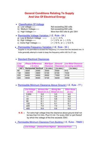
Classification Of Voltage
a) Low voltage------ Not exceeding 250 volts
b) Medium Voltage------ Not exceeding 650 volts
c) High Voltage------ More than 650 volts & upto 33kV
Permissible Voltage Variation ( I.E. Rule - 54 )
a) Low & Medium Voltage ------ ( - ) ( + ) 6 %
b) High Voltage------ ( + ) 6 % or ( - ) 9 %
c) Extra High Voltage------ ( + ) 10 % or ( - ) 12.5 %
Permissible Frequency Variation ( I.E. Rule - 55 )
Supplier is not permitted to exceed the frequency 3 % more than the declared one. In
India generally attempt is made to keep the frequency within 48.5 to 51 cps.
Standard Electrical Clearances
Line Phase Difference Mid-Span Ground Live Metal Clearance
Voltage ( in mm.) Clearance Clearance (no swing condition)
( kV ) Horizontal Vertical ( in mm.) ( in mm.) ( in mm.)
66 3500 2000 3000 5500 915
132 6800 3900 6100 6100 1530
220 8400 4900 8500 7000 2130
400 9000 8000 9100 8400 3050
Permissible Minimum Clearance Above Ground ( I.E. Rule - 77 )
Line Voltage Across the Along the Other Areas
(in kV) Street (in m.) Street (in m.) (in m.)
0.650 5.8 5.5 4.6
11 6.1 5.8 4.6
33 6.1 5.8 5.2
66 6.1 6.1 5.5
132 6.1 6.1 6.1
220 7.0 7.0 7.0
400 8.8 8.8 8.8
N. B. :- For extra high voltage lines the clearance above ground shall not
be less than 5.2 mtrs. Plus 0.3 mtr. For every 33kV or part thereof
by which the voltage of the line exceeds 33kV.
Permissible Minimum Clearance From Building ( I.E. Rules - 78&80 )
Line Voltage Vertical From Highest Horizontal From
2. (in kV) Object (in m.) Nearest Point
(in m.)
0.650 2.5 1.2
11 3.7 1.2
33 3.7 2.0
66 4.0 2.3
132 4.6 2.9
220 5.5 3.8
400 7.3 5.6
Clearance Of Overhead Lines Crossing Each Other ( I.E. Rule - 87 )
Line 11kV 33kV 66kV 132kV 220kV 400kV
Voltage (in m.) (in m.) (in m.) (in m.) (in m.) (in m.)
(in kV)
0.250 2.44 2.44 2.44 3.05 4.58 6.00
0.650 2.44 2.44 2.44 3.05 4.58 6.00
11 2.44 2.44 2.44 3.05 4.58 6.00
33 2.44 2.44 2.44 3.05 4.58 6.00
66 2.44 2.44 2.44 3.05 4.58 6.00
132 3.05 3.05 3.05 3.05 4.58 6.00
220 4.58 4.58 4.58 4.58 4.58 6.00
400 6.00 6.00 6.00 6.00 6.00 6.00
N. B. :- # Suitable guarding arrangement should be provided to guard against
possibility of coming in contact with each other.
# No guarding is required when an extra high voltage line crosses
over another extra high voltage / high voltage / medium voltage line.
# Crossing shall be made as nearly at right angles, as near the
support of the upper line. Support of the lower line shall not be
erected below the upper line.
Railway Crossing Clearances
Line Voltage Broad Gauge & Narrow Gauge
( in mtrs. )
Up to and including 11kV Normally by Cable
Above 11kV and up to 66kV 14.10
Above 66kV and up to 132kV 14.60
Above 132kV and up to 220kV 15.40
Above 220kV and up to 400kV 17.90
En-route Tree Clearance From Over Head Lines
Line On Either Side Of The Line
( in mtrs. )
Extra High Voltage Line 12.19
High Voltage Line 6.095
3. Low & Medium Voltage Line 0.914
Clearance Over The River
Clearance must be minimum of 3.048 metres over highest flood level ( in
case of non-navigable river ). In case of navigable river clearance must be
decided in relation to the tallest mast of the ship passing through the river.
Clearance Between Power And Communication Lines
a) Low and medium voltage line ----- 1380 mm ( 4’6” )
b) H.V. lines up to & including 7.2 kV ----- 1525 mm ( 5’0” )
c) H.V. lines up to 12 kV ----- 2130 mm ( 7’0” )
Clearance between communication and ground wires will not be less
than 1070 mm ( 3’6” ). The minimum clearance between the guard wires and
telecommunication lines shall be 600 mm. If the guards are fastened to the
same supports as the power line, then the minimum distance will be 900 mm.
Line Clearance In WBSEB System
Line Voltage Ph - Ph Ph - E Ground Clearance
( kV ) (mts.) (mts.) (mts.)
Single Double Single Double Single Double
Circuit Circuit Circuit Circuit Circuit Circuit
400 11 8 9.26 9.30 8.84 8.84
220 7.55 7.8 4.9 4.9 7.015 7.015
132 5.37 5.63 4.0 4.0 6.10 6.10
66 4.8 3.44 5.49
Total Number Of Disc Insulators In A String
Line Voltage ( kV ) Suspension String Tension String
66 5 6
132 9 10
220 14 15
400 22 23
Switchyard Parameters
Phase Clearance (Outdoor) Bus
Bus Voltage (kV) Ph - Ph (mts.) Ph - E (mts.) Bay Width (mts.)
33 1.3 1.9 6.1
4.
5. 66 1.7 2.2 7.7
132 2.8 3.4 12.2
220 4.5 4 17
400 7 6.5 27
Bus Height
Bus Voltage (kV) Low Bus (mts.) Main Bus (mts.) Jack Bus (mts.)
132 5.5 8.42 12.85
220 6.25 10.95 16.5
400 8.2 15.5 23
Earthing Resistance (Ideal Value)
Generating Station and Big Sub-Station : 0.5
132 kV Sub-Station : 1
66 kV Sub-Station : 2 - 4
33 kV Sub-Station : 4 - 6
Current Carrying Capacity Of Underground Cable
Conductor 6.6 & 11 kV 6.6 & 11 kV insulated 6.6 & 11 kV XLPE
Size P.I.L.C. armoured, armoured, screen Cable Aluminium
(sq. mm) served belted, 3 sheathed, Aluminium Conductor
core Aluminium Conductor (Amps) (Amps)
Conductor (Amps)
Single Core Three Core Single Core Three Core
In In Air In In In In In In In In
Ground Grou Air Grou Air Grou Air Grou Air
nd nd nd nd
16 58 50 - - - - - - - -
7. Important Data Of All Aluminium Conductor ( A.A.C. )
Code Ward Strand Size Cu. Eq. Nominal Nominal Max. Current Resistance at Approx. ultimate Approx. Weight
(mm.) SWG Copper Area Aluminium Carrying 20
0
C Tensile Strength (Kg/KM)
No. (sq. mm) Area Capacity At (Ohms/KM) (Kg)
(sq. mm) 40
0
C Ambient
(Amp.)
Canops 7 / 1.96 8 13 20 105 1.362 385 58
Gnat 7 / 2.21 7 16 25 125 1.071 485 73
Weevil 7 / 2.44 6 20 30 145 0.879 580 89
Ant 7 / 3.10 3 30 50 200 0.544 892 144
Important Data Of Aluminium Conductor Steel Reinforced ( A.C.S.R. )
Code Ward Nominal Calculated No. Of Dia. Of Overall Max. Current Resistance at Approx. Approx.
Copper Eq. Area Of Wires Wires Dia Of Carrying 20
0
C ultimate Weight
Area (sq. Aluminium (mm) Conducto Capacity At (Ohms/KM) Tensile (Kg/KM)
mm (sq. mm) r (mm) 40
0
C Ambient Strength
Al. St. Al. St. (Amp.) (Kg)
Squirrel 13 20.71 6 1 2.11 2.11 6.33 115 1.374 771 85
Weasel 20 31.21 6 1 2.59 2.59 7.77 150 0.9116 1136 128
Rabbit 30 52.21 6 1 3.35 3.35 10.05 200 0.5449 1860 214
Raccoon 48 77.83 6 1 4.09 4.09 12.27 270 0.3656 2746 318
Dog 65 103.6 6 7 4.72 1.57 14.15 324 0.2745 3299 394
Panther 130 207.0 30 7 3.00 3.00 21.00 520 0.1375 9127 976
Deer 260 419.3 30 7 4.27 4.27 29.89 806 0.06786 18230 1977
Zebra 260 418.6 54 7 3.18 3.18 28.62 795 0.0680 13316 1623
Moose 325 515.7 54 7 3.53 3.53 31.77 900 0.05517 16250 2002
8. Recommended Size Of Fuses
Fuses are overcurrent devices and must have ratings well above the maximum
transformer load current in order to carry without ‘blowing’ during the short duration
overloads that may occur because of motor starting. Also the fuses must able to withstand
the magnetising inrush current drawn when the power transformers are energised.
POWER TRANSFORMER
Sl. Transformer Voltage High Voltage Side Low Voltage Side
No. Capacity Ratio (33 kV) (11 0r 6.6 kV)
(MVA) (kV) Full load Size of Full load Size of
current fuse wire current fuse wire
(amps.) (SWG) (amps.) (SWG)
1. 0.50 33/6.6 8.75 28 48 18
2. 1.00 33/6.6 17.5 23 96 14
3. 3.00 33/6.6 52.5 17 288.7 OCB
4. 0.50 33/11 8.75 28 26.3 21
5. 0.63 33/11 11.0 24 33.0 21
6. 1.00 33/11 17.5 23 52.5 15
7. 1.60 33/11 28.0 21 84.0 14
8. 3.15 33/11 55.0 17 165.3 2 X 14
9. 5.00 33/11 87.5 OCB 262.4 OCB
10. 6.30 33/11 110.2 OCB 330.6 OCB
DISTRIBUTION TRANSFORMER
Sl. Transformer Voltage High Voltage Side Low Voltage Side
No. Capacity Ratio (11 0r 6.6 kV)
(MVA) (kV) Full load Size of Full load Size of
current fuse wire current fuse wire
(amps.) (SWG) (amps.) (SWG)
1. 25 6.6/0.4 2.4 38 36 22
2. 63 6.6/0.4 6.0 35 91 17
3. 100 6.6/0.4 9.6 28 149 12
4. 25 11/0.433 1.31 39 33.3 22
5. 63 11/0.433 3.30 38 84.0 17
6. 100 11/0.433 5.25 35 133.3 1 X 14
7. 200 11/0.433 10.5 28 266.6 HRC 250
8. 250 11/0.433 13.12 25 333.3 HRC 320
Construction Of Transmission And Distribution Lines
9. Transmission means conveyance of electrical power at Extra High Voltage
from the generating stations to the grid Sub-stations or between Grid Sub-Stations.
Distribution is the term used for conveyance of electrical power from the Sub-
stations to the actual consumers at high or medium or low voltage.
Transmission & distribution of power can be done with the help of -
i) Overhead lines
ii) Underground cables.
Type Of Power Advantages Disadvantages
Transmission
Overhead lines Cheaper Prone to disturbances from
Easy to maintain weather, lightning strokes
etc.
Underground cables Easy for power Takes longer time for
distribution in congested
breakdown repair.
urban areas, factories, Costlier
residences, power houses,
Sub-stations etc.
1. The main items in an over head line are :
a) Conductor, b) Supports, c) Insulators, d) Metal Hardware
a) Conductor
The principal materials used as conductors in construction of overhead lines are -
i) Hard drawn copper,
ii) All Aluminium Conductor (AAC)
iii) Aluminium Conductor Steel Reinforced (ACSR)
iv) Cadmium Copper
i) Steel
v) All Aluminium Alloy Conductor (AAAC)
i) Aluminium Conductor Alloy Reinforced (ACAR)
vi) Aluminium Alloy Conductor Steel Reinforced (AACSR)
b) Supports
i) Wood poles
ii) Steel Tubular poles
iii) Rails and R.S. Joists
iv) Lattice type poles
v) Steel Towers
vi) Reinforced cement concrete poles (RCC)
vii) Pre-stressed cement concrete poles (PCC)
c) Insulators
i) Pin insulators
ii) Shackle insulators
iii) Disc insulators
iv) Strain insulators
10. i) Post insulators
d) Metal Hardware
i) Strain clamp
ii) Suspension clamp
iii) Twisting joint sleeve
iv) Repair sleeve
v) Bolted clip
vi) Tubular compression joint
vii) Parallel Groove clamp (P.G.)
viii) Vibration damper
2. Other Factors For Line Construction
i) Bracket or cross arm
ii) Earthing system
iii) Stay and struts
iv) Foundation
v) Jointing
vi) Armoring
vii) Dumper
viii) Guard and safety device
ix) Anti climbing device
x) Danger notice
xi) Pole numbering
Functions Of Transmission (O&M) Sub-Division
1. Attending breakdown of lines and Sub-Stations.
2. Preventive maintenance work
i) Winter maintenance program.
11. ii) Pre-puja maintenance work.
iii) Pre-norwester maintenance work.
3. Procurement of spare equipment and equipment’s spares for both
breakdown replacement and preventive maintenance work.
4. Up-keepment of control room building switchyard by periodical
maintenance through annual maintenance program.
5. Ensuring round the clock vigilance for maintenance of power system.
a) Through the duty roaster of operational staff, arrangement of
necessary availability of maintenance staff, vehicle for attending
breakdown jobs at the shortest possible time.
b) Maintaining proper communication system with other Sub-station from which
power is drawn and other distribution Sub-Stations and bulk consumer
through which power is distributed.
6. Means of communication :
i) P & T telephone
ii) VHF communication
iii) PLCC ( power line carrier communication )
iv) Future communication - VSAT communication
i) Maintaining walkie-talkie sets for small distance communication.
v) Allotment of staff quarters for emergency maintenance & operational staff.
7. Operation of the Sub-station :
Switching instruction are displayed in all Sub-stations for switching
operation of different equipment during faulty condition or shutdown
operation or interchanging of source of supply, shedding of power in case
of scarcity in availability as directed by Central Load Despatch and also to
save the system from total disaster.
Functions Of Transmission Construction Sub-Division
Construction Of Sub-Station :-
1. Selection of site and acquisition process of the land through land acquisition
department, Govt. of West Bengal with the assistance of the land acquisition cell
of WBSEB, after issuance of work order by the CP & ED wing.
2. Soil testing work to facilitate CP & ED wing to prepare the design of foundation of
structures and equipment and also control room building, staff quarters etc.
3. Preparation of estimate for boundary wall, foundation of equipment and
structures, control room building on the basis of soil testing report for tender call.
4. Preparation of estimate for erection of structures and equipment as per lay out
drawing submitted by CP & ED wing.
12. 5. Preparation of list of materials and equipment like - isolators, C.Ts., L.As., OCBs
etc. are to be prepared and requisition of materials are to be placed to CP & ED
wing through proper channel for procurement action.
6. Estimate for -
a) earthmat arrangement for earthing of equipment.
b) cable trenches are also to be prepared as per layout drawing.
c) similar estimate for land filling work, surface drain work, construction of store
shed, staff quarters, children park, recreation room etc. should also be
prepared for inviting tenders for construction work.
7. List of equipment to be installed for inside the control room like control pannel,
battery charger pannels and control cable for connecting equipment in the switchyard
with the control pannel should also be prepared for procurement action by the CP &
ED / Central purchase wing.
Construction Of Over head Transmission Line:-
1. By preliminary route survey, alternative routes or alignment are to be prepared
avoiding congested areas, railway crossings, roads, rivers, as far as practicable.
2. Gazette notification & newspaper publication will be necessary mentioning the
names of Mouzas through which the line will pass for general information of
public in terms of section 29 & 42 of I.E. Act, 1948.
3. Soil resistivity test is to be conducted along the route alignment and after that,
schedule of towers involving the angle at different points are to be prepared.
i) ‘A’ type tangent tower tolerable angle up to 2
0
ii) ‘B’ type tower tolerable angle 2
0
to 30
0
iii) ‘C’ type tower tolerable angle 30
0
to 60
0
iv) ‘D’ type tower above 60
0
and dead-end tower.
The foundation of the towers are designed according to the condition of the soil
over which the route alignment is drawn -
i) dry soil
ii) semi-submerged soil
iii) fully submerged soil.
4. After getting the preliminary survey report, specification for supply of different
kind of towers and required foundation are to be prepared for tendering purpose.
5. Permission for Rly. Crossing & forest deptt. & clearance for environment deptt. &
Airport Authority, National High way Authority are to be taken.
TRANSFORMER PROTECTION
Protection Is Provided To Minimise -
a) Cost of repair of damage.
b) Possibility of spreading & involving other equipment.
c) Timely out of service of the equipment.
d) Loss in revenue and of course the strained public relations.
Protection System Should Be -
13. a) Very fast - Operate with correct speed i.e. fast clearance of fault to minimise damage
and increase power system stability.
b) Selective - Able to discriminate between faulty & healthy equipment.
c) Sensitive - Can operate under minimum generating condition and
d) Stable - Stabilise under external fault condition and should not result in
undesired tripping when there is no fault in the equipment protected.
TRANSFORMER IS VIRTUALLY AN IMPEDANCE CONNECTED TO THE SYSTEM.
Faults In Transformer
Sl. Fault Causes Effect Occurrence
No.
1. Phase Fault Mostly ground faults in High current, Rare
(Phase to 2 phases, flashover, Mechanical Stress.
Phase) insulation failures.
2. Ground Fault Insulation failure. High current in grounded Common
neutral operation.
3. Inter Turn Insulation failure. Short circuit current is Common
Fault high but line terminal
current is low.
4. Inter Winding Insulation failure Over voltage leading to Rare
Fault between windings - developing ground fault.
primary to secondary.
5. Core Fault Laminations getting Eddy current heating Common
bridged, core bolt
increases,
insulation failure. Increase of noise.
6. Radiator Choking of pipes by Abnormal heating, Common
Fault, sludge in oil, cooling Winding damage,
Cooling duct ducts also may be Oil break down and gas
Fault affected. formation.
In our system transformer ratings up to 3 MVA are generally protected only by fuse.
Fuses are over-current devices and must have ratings well above the maximum
transformer load current in order to carry, without blowing, the short duration over loads
that may occur because of such as motor starting, also the fuses must withstand the
magnetising inrush current drawn when power transformers are energised.
The protection provided for large capacity transformers are described hereunder –
1) Temperature Relay :
The temperature indicator is fitted with mercury switches fixed on the pointer, so that
on temperature rise, the switch tilts and makes contact through mercury between two
electrodes which are connected to electric to initiate proper action. Detection of over-
heating is normally done by –
a) Oil Temperature Indicator (OTI)
b) Winding Temperature Indicator (WTI) – The winding temperature is indirectly
obtained by measuring the top oil temperature by a Bourdon liquid expansion
indicator mounted in a pocket, which also contains a heater element energised
from a phase CT. The thermometer thus measures top oil temperature plus an
increment proportional to load current.
14. Settings of WTI & OTI in WBSEB for several actions –
Protection System Cooling System
Alarm Trip Fan ON Fan OFF Pump ON Pump OFF
O.T.I. 80
o
C 90
o
C - - - -
W.T.I. 90
o
C 95
o
C 65
o
C 55
o
C 70
o
C 60
o
C
2) Oil and Gas Devices :
a) Boucholz Relay / Protective Surge Relay – When a transformer is fitted with conservator,
the formed gas within the transformer, flows towards the conservator where atmospheric
pressure exists. Boucholz Relay is mounted in the pipe which has a slope between main
tank and conservator. If the fault is of very minor nature, gases are liberated slowly and
stream of gas bubbles flow towards conservator. But if there is violent evolution of gas, a
sudden surge of oil flow towards the conservator followed by the gaseous products.
Bucholz relay has two floats with mercury switches attached –
i) The upper float (for alarm) moves down when gas slowly accumulates on the
upper part of the chamber (result of incipient fault, failure of lamination insulation /
core bolt insulation / interturn fault).
ii) A surge of oil however deflects the lower float (for trip) and closes mercury switch
(indicating heavy fault / short circuits). In this case gas may not accumulate in relay.
For a loss of oil condition also, both the floats make contacts of the corresponding
mercury switch (low oil level condition).
I.S.S. (Indian Standard Specification) 3637 – 1966 sets down the following figures
relating to a Bucholz relay –
Nominal Pipe Bore (mm.) Gas volume for alarm at 5 Steady oil flow for trip at
o
pipe angle (cc) 1-9
o
pipe angle (cm/sec)
25 90 – 165 70 – 130
50 175 – 225 75 – 140
80 200 – 300 90 – 160
N.B. – 1. Often after initial energisation of transformer, the trapped air get released
by vibration & warming up of the oil and operate the Bucholz Relay. To prevent this
proper release of air from bushing turrets, radiators, tank-tops are required.
2. Oil surges also occur when the transformer feeds external short circuits and
there is dynamic stress in the windings. Thus if Bucholz Relay is made very
sensitive, there is chance of operation for fault outside the transformer.
Type of Relay -
Relay No. Name Of The Relay
2 Time delay relay
3 Checking or interlocking relay
21 Distance protection relay
25 Synchronising / Syn. Check relay
27 Under voltage check relay
15. 30 Annunciation relay
32 Directional power relay
37 Under current or under power relay
40 Field failure relay
46 Reverse phase or phase balance current relay
49 Machine or transformer thermal relay
50 Instantaneous over-current relay
50 N Instantaneous earth-fault relay
51 IDMT (Inverse Definite Minimum Time) O/C relay
51 N IDMT (Inverse Definite Minimum Time) E/F relay
52 Circuit Breaker
52 a Circuit Breaker auxiliary contact N/O
52 b Circuit Breaker auxiliary contact N/C
55 Power factor relay
56 Field application relay
59 Over voltage relay
60 V / I balance relay
64 REF (Restricted Earth Fault) Relay
67 Directional O/C & E/F relay
68 Blocking relay
74 Supervision relay
79 AC reclosing relay
80 DC fail relay
86 Lock out / Trip
87 Differential relay
Protective Relays
Over Current Relay
Excessive current flow through an electrical circuit due to a fault in any part of the
network or due to abnormal operating condition in the system, is most conveniently
detected by overcurrent relays which operate when the magnitude of current through
it exceeds a set value. These are again of the following types -
16. i) Instantaneous - time a few cycles only
ii) Definite time - fixed intentional time delay independent of current magnitude
iii) Inverse time - operating time decreases as actuating current increases.
According to the characteristics, these are classified as
- a) Inverse, b) Very Inverse, c) Extremely Inverse.
The most commonly used type of relays work on induction (electromagnetic)
principle and develop torque proportional to I
2
. Hence the torque increases rapidly
with current, but beyond a certain value of current depending on the core
construction, saturation sets-in and the induction decreases so that further increase
of current does not increase the torque and the relay operating time levels out to a
definite time. Such characteristic is known as Inverse Definite Minimum Time (IDMT).
Fault Calculation
For determining the settings of relays a knowledge of the fault current that can
flow through the network into the fault is necessary. Hence the data required for the
setting study are :
a) Single line diagram of the system with ratings and impedance of Generators,
Transformers, Feeders with details of CTs and protective relays shown.
b) Maximum and minimum of short circuit current expected to flow through each
protective device.
c) Characteristic curve of relays.
d) Maximum peak load current through the protective device including starting
current of motors, if supplied.
The basic principle followed in relay settings is to allow shortest operating time for
maximum fault current and then recheck the time co-ordination at minimum fault current.
For the calculation of the fault current, the data of %IZ or the line impedance in ohms
must refer to a common base MVA and base voltage level. With the above the network may
be reduced to a single source with series impedance for ease in fault current calculation.
Base MVA is the 3-phase power
Base voltage is line voltage in kV
We know, MVA = 1000 . kV . I = 1000 . kV . ( V / Z )
= 1000 . kV . { ( kV / 1000 ) / Z } = ( kV )
2
/ Z
So, Base Impedance = ( kV )
2
/ MVA
Per unit impedance = (Actual Impedance) / (Base Impedance)
= Z / {( kV )
2
/ MVA } = Z . (Base MVA) / (Base kV )
2
Z p.u. (new base MVA) = Z p.u. (given base MVA) X [(new base MVA) / (given base MVA)]
Z p.u. (new base kV) = Z p.u. (given base kV) X [(new base kV) / (given base kV)]
2
Example :
10 Miles 5 Miles
132 kV 0.6 / m 0.6 / m
Source
17.
18. 33 / 11 kV
A B C 10 MVA, 7% % D
132 / 33 kV
50 MVA, 10%
The h.v. source is assumed to have negligible source impedance. Converting all the
impedance to a common base MVA of say 100 MVA,
Tr. at D, % impedance on 100 MVA = 7 x (100 / 10) = 70 % = 0.7 p.u.
Line BC, % impedance = (5 x 0.6 x 100) / 33
2
= 0.2754 p.u.
Line AB, % impedance= (10 x 0.6 x 100) / 33
2
= 0.55 p.u.
50 MVA Tr., % impedance on 100 MVA = 10 x (100 / 50) = 20 % = 0.2 p.u.
2 x 50 MVA Tr. in parallel, % impedance on 100 MVA = 10 % = 0.1 p.u
Fault Levels
At Bus D = 100 / (0.7 + 0.2754 + 0.55 + 0.1) = 61.35 MVA
At Bus C = 100 / (0.2754 + 0.55 + 0.1) = 107.53 MVA
At Bus B = 100 / (0.55 + 0.1) = 153.85 MVA
At Bus A, Maximum = 100 / 0.1 = 1000 MVA
Minimum = 100 / 0.2 = 500 MVA
Considering only one 50 MVA Tr. in service, the minimum fault levels are -
At Bus D = 57.9 MVA
At Bus B = 97.5 MVA
At Bus C = 133.3 MVA
At Bus A = 500 MVA
Location Fault MVA Fault Current, Amps.
Maximum Minimum Maximum Minimum
A 1000 500 17540 8770
B 154 133.3 2700 2340
C 108 97.5 1900 1710
D 61.5 57.9 1080 1010
Alternative Method :
The same calculation of fault current could as well be done from ohmic values of the
impedance in the circuit.
Z in ohm = Z p.u. x kV
2
/ MVA
2.18 For 50 MVA Tr. at 33 kV, Z = 0.1 x 33
2
/ 50 =
For the transformers in parrel at 33 kV side, Z s = 1.09
Line AB, ZAB = 6
Line BC, ZBC = 3
7.623 For 10 MVA Tr. at 33 kV, Z T = .07 x 33
2
/ 10 =
Fault at A at 33 kV side, I FA = (33 / 3) / 1.09 = 17480 amps.
Fault at B, I FB = (33 / 3) / (6 + 1.09) = 2687 amps.
Fault at C, I FC = (33 / 3) / (3 + 6 + 1.09) = 1888 amps.
Fault at D at 33 kV side, I FD = (33 / 3) / (7.623 + 3 + 6 + 1.09) = 1075 amps.
at 11 kV side, I FD = (11 / 3) / (7.623 + 3 + 6 + 1.09) = 3225 amps.
Selection Of CT Ratios :
The CT ratios for each section of the feeders are selected from the data of maximum
load current flowing into the section. The settings of the protective relays should be safely