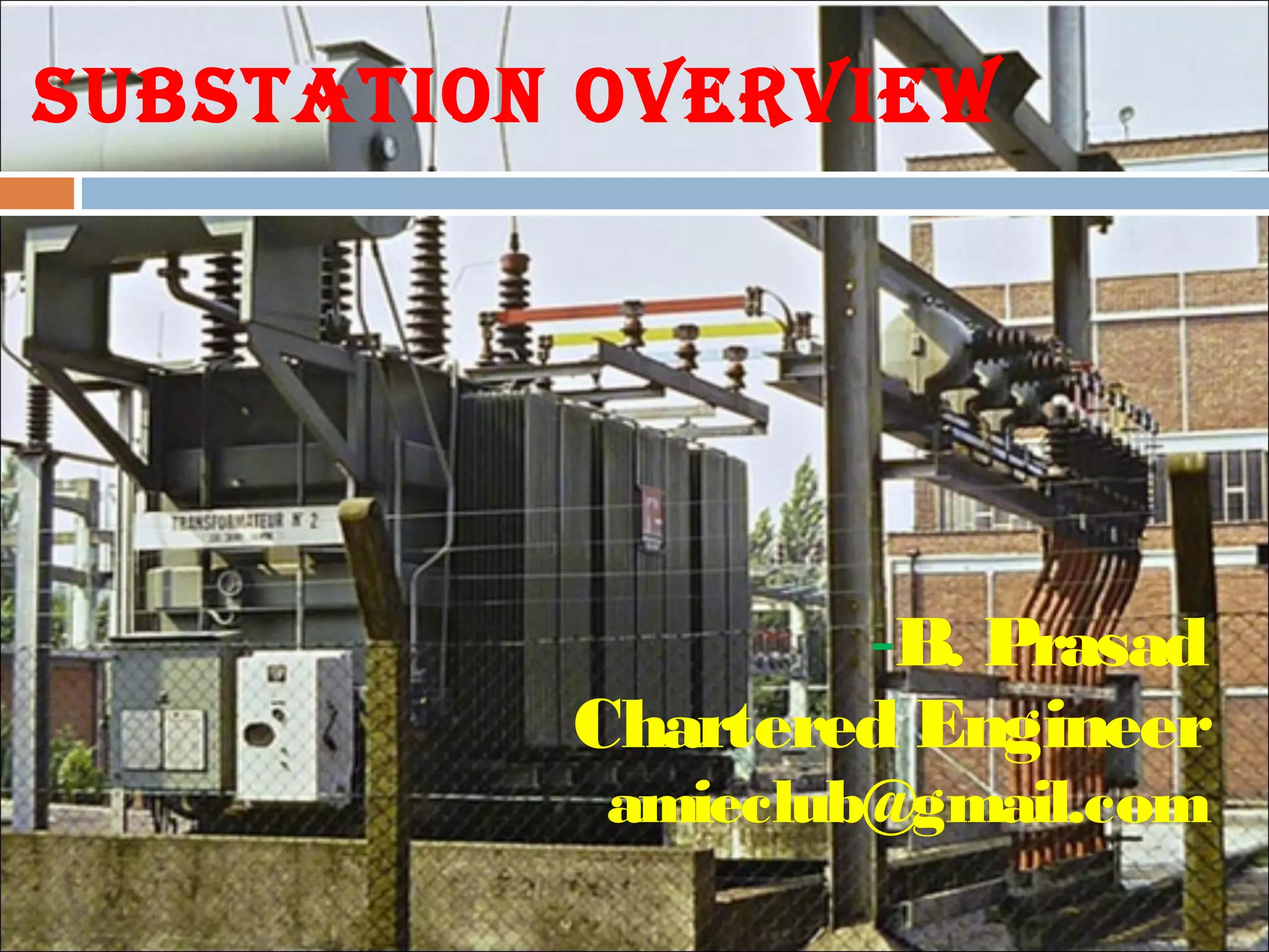
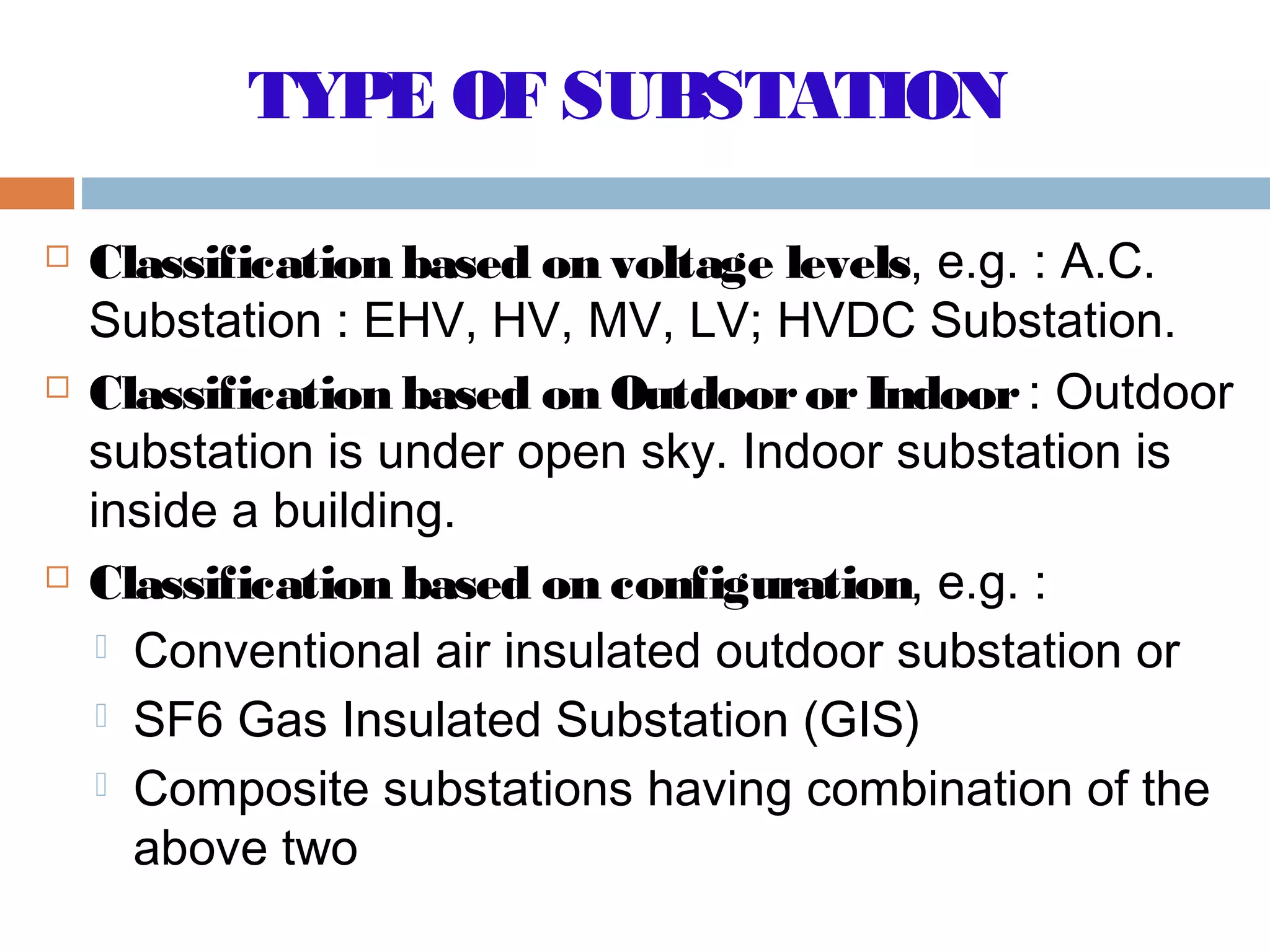
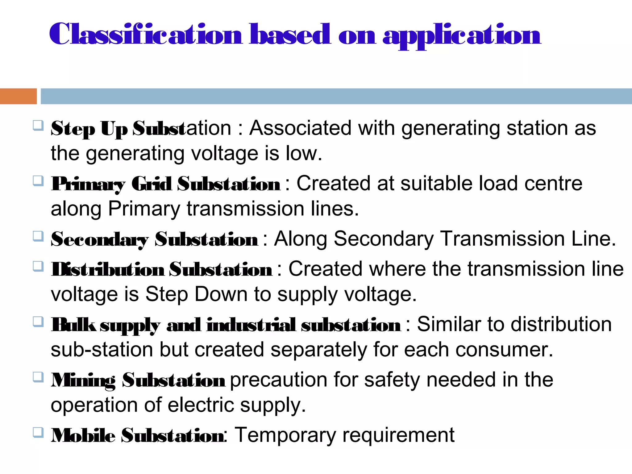
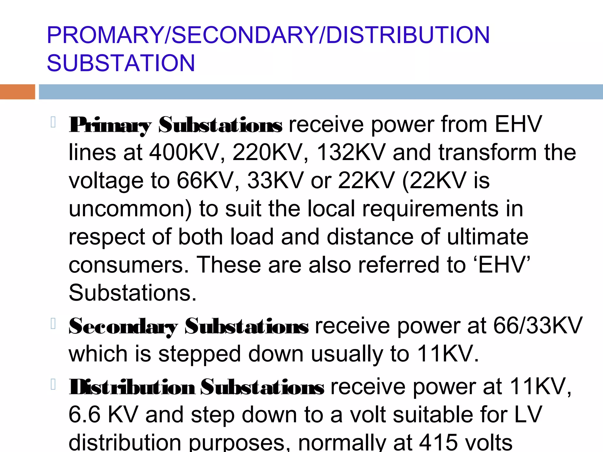
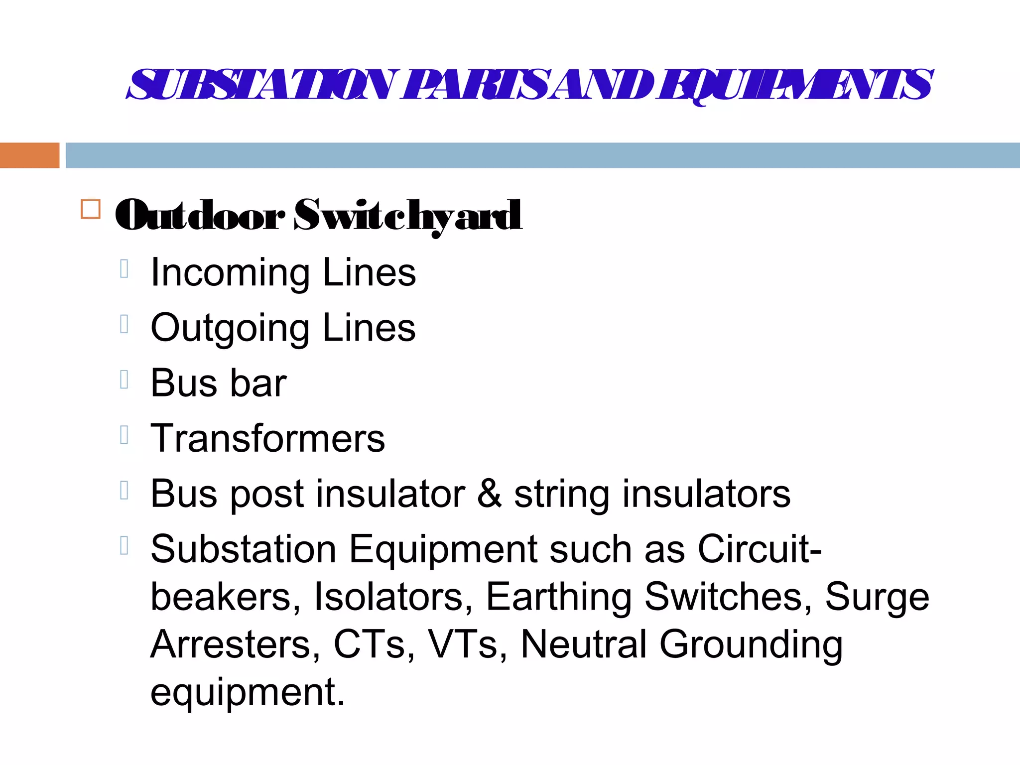
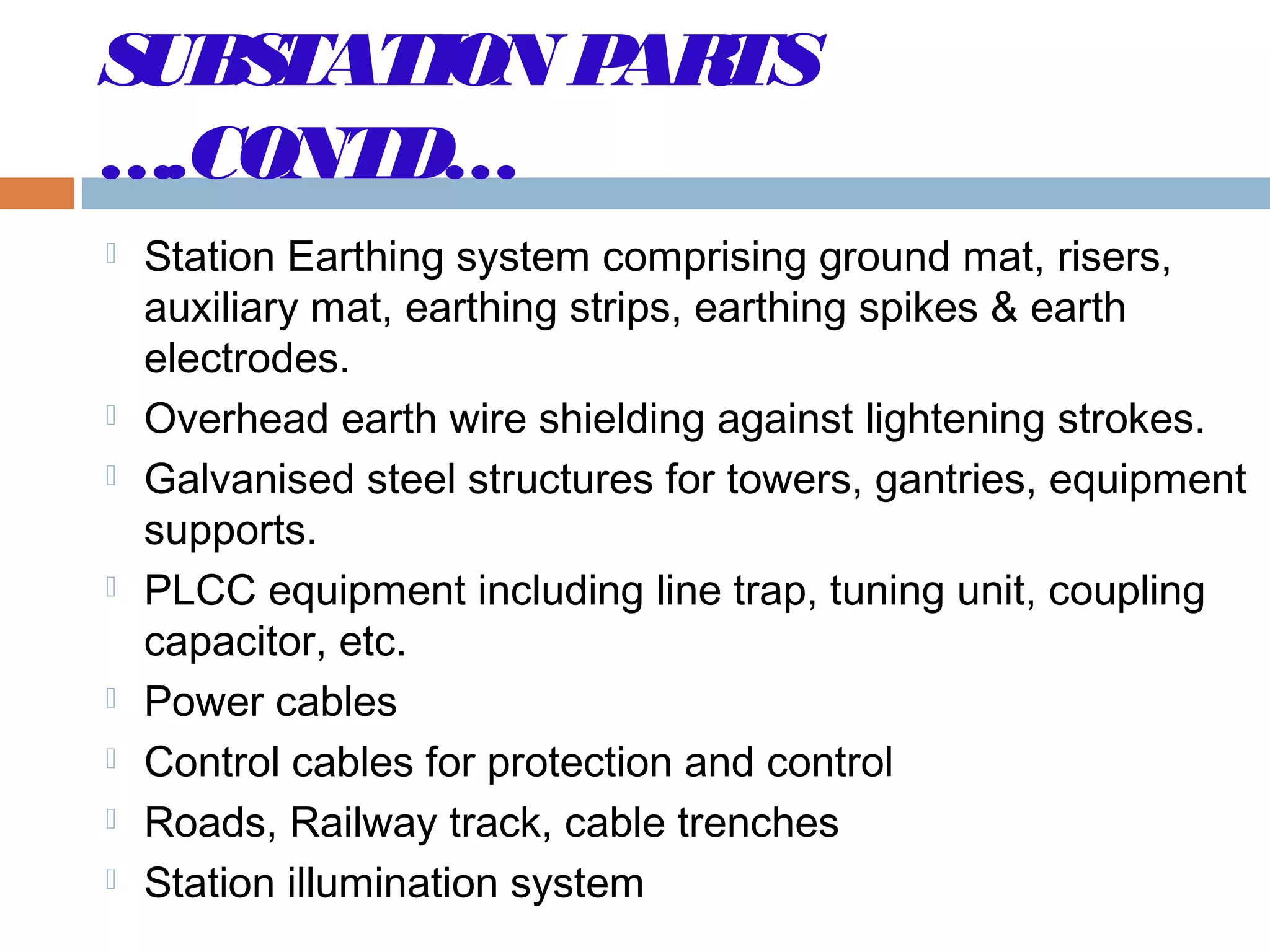
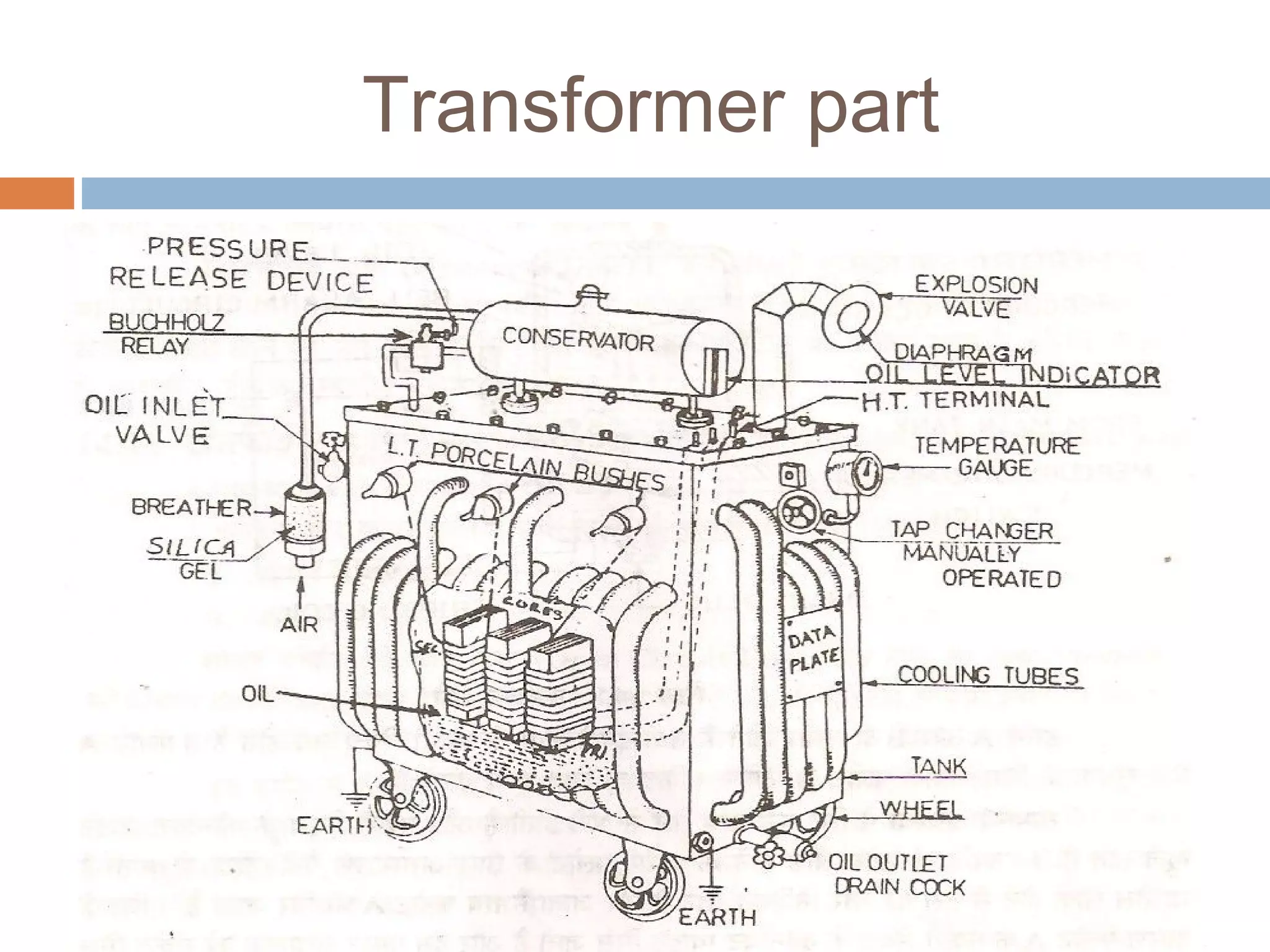
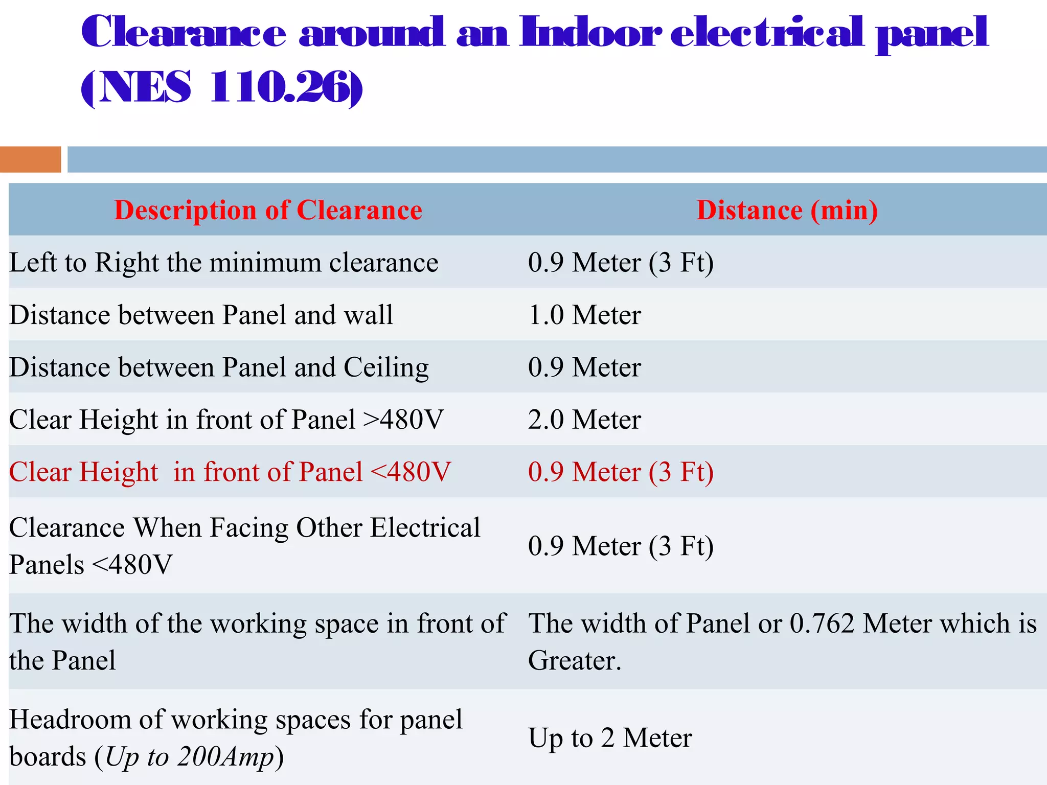
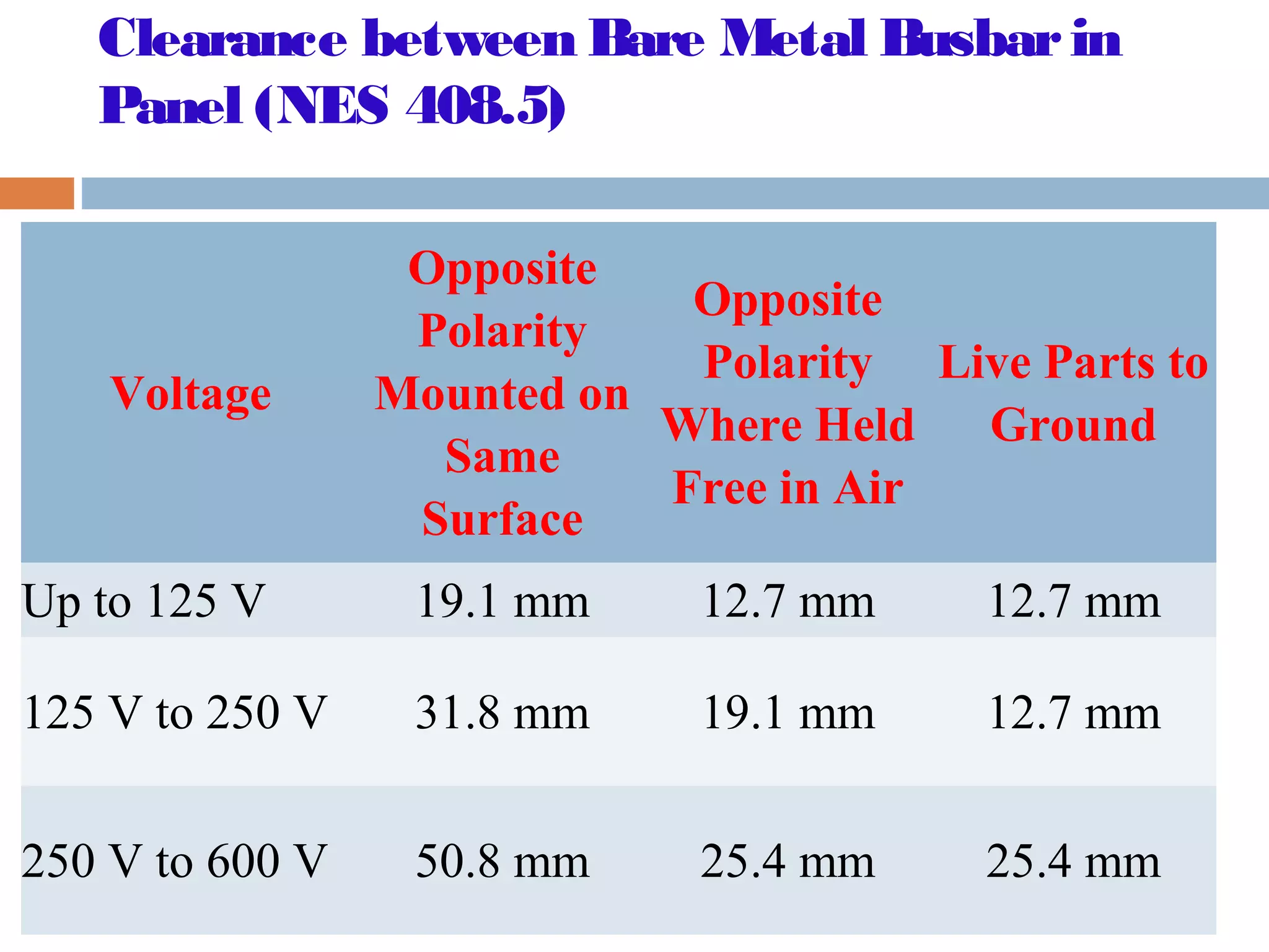
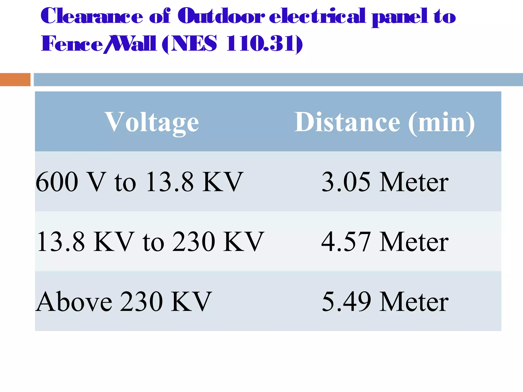
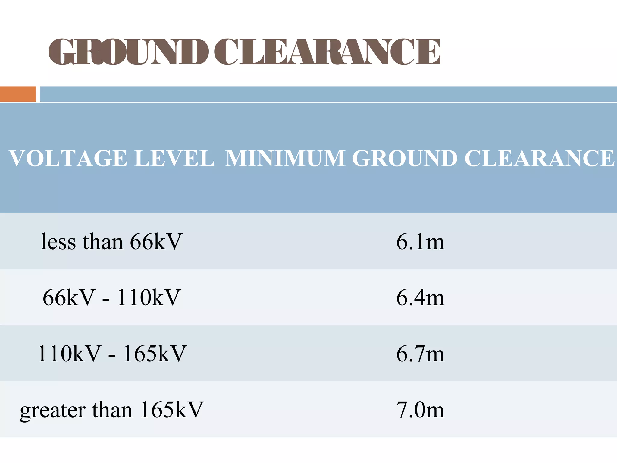
SUBSTATION OVERVIEW
-B. Prasad
Chartered Engineer
amieclub@gmail.com
TYPE OF SUBSTATION
 Classification based on voltage levels, e.g. : A.C.
Substation : EHV, HV, MV, LV; HVDC Substation.
 Classification based on OutdoororIndoor: Outdoor
substation is under open sky. Indoor substation is
inside a building.
 Classification based on configuration, e.g. :
 Conventional air insulated outdoor substation or
 SF6 Gas Insulated Substation (GIS)
 Composite substations having combination of the
above two
Classification based on application
 Step Up Substation : Associated with generating station as
the generating voltage is low.
 Primary Grid Substation : Created at suitable load centre
along Primary transmission lines.
 Secondary Substation : Along Secondary Transmission Line.
 Distribution Substation : Created where the transmission line
voltage is Step Down to supply voltage.
 Bulksupply and industrial substation : Similar to distribution
sub-station but created separately for each consumer.
 Mining Substation precaution for safety needed in the
operation of electric supply.
 Mobile Substation: Temporary requirement
PROMARY/SECONDARY/DISTRIBUTION
SUBSTATION
 Primary Substations receive power from EHV
lines at 400KV, 220KV, 132KV and transform the
voltage to 66KV, 33KV or 22KV (22KV is
uncommon) to suit the local requirements in
respect of both load and distance of ultimate
consumers. These are also referred to ‘EHV’
Substations.
 Secondary Substations receive power at 66/33KV
which is stepped down usually to 11KV.
 Distribution Substations receive power at 11KV,
6.6 KV and step down to a volt suitable for LV
distribution purposes, normally at 415 volts
SUBSTATION PARTSANDEQUIPMENTS
 OutdoorSwitchyard
 Incoming Lines
 Outgoing Lines
 Bus bar
 Transformers
 Bus post insulator & string insulators
 Substation Equipment such as Circuit-
beakers, Isolators, Earthing Switches, Surge
Arresters, CTs, VTs, Neutral Grounding
equipment.
SUBSTATION PARTS
….CONTD…
 Station Earthing system comprising ground mat, risers,
auxiliary mat, earthing strips, earthing spikes & earth
electrodes.
 Overhead earth wire shielding against lightening strokes.
 Galvanised steel structures for towers, gantries, equipment
supports.
 PLCC equipment including line trap, tuning unit, coupling
capacitor, etc.
 Power cables
 Control cables for protection and control
 Roads, Railway track, cable trenches
 Station illumination system
SINGLE LINE DIAGRAM
Transformer part
Batteries forindustrial orsubstation applications
 Vented /
Flooded Lead
Acid batteries
 Sealed
maintenance
free
batteries/Valve
Regulated Lead
Acid
 Nickel Cadmium
(Ni-cd) batteries
Battery AH
 LOAD CURRENT 10A for
3 hrs.
 Cell voltage =12V DC
 CALCULATION ,
AH=10X3
 CAPACITY =30/
(0.75X0.8)=50AH
 Discharge factor=0.7
 Ageing factor =0.8
 Drain capacity =C10
CHARGER
 Type of charger
 Input voltage
 output voltage
 Application
 Protection
 Metering
 Indication
 Alarms
 Auto operation
Clearance around an Indoorelectrical panel
(NES 110.26)
Description of Clearance Distance (min)
Left to Right the minimum clearance 0.9 Meter (3 Ft)
Distance between Panel and wall 1.0 Meter
Distance between Panel and Ceiling 0.9 Meter
Clear Height in front of Panel >480V 2.0 Meter
Clear Height in front of Panel <480V 0.9 Meter (3 Ft)
Clearance When Facing Other Electrical
Panels <480V
0.9 Meter (3 Ft)
The width of the working space in front of
the Panel
The width of Panel or 0.762 Meter which is
Greater.
Headroom of working spaces for panel
boards (Up to 200Amp)
Up to 2 Meter
Clearance between Bare Metal Busbarin
Panel (NES 408.5)
Voltage
Opposite
Polarity
Mounted on
Same
Surface
Opposite
Polarity
Where Held
Free in Air
Live Parts to
Ground
Up to 125 V 19.1 mm 12.7 mm 12.7 mm
125 V to 250 V 31.8 mm 19.1 mm 12.7 mm
250 V to 600 V 50.8 mm 25.4 mm 25.4 mm
Clearance of Outdoorelectrical panel to
Fence/Wall (NES 110.31)
Voltage Distance (min)
600 V to 13.8 KV 3.05 Meter
13.8 KV to 230 KV 4.57 Meter
Above 230 KV 5.49 Meter
GROUNDCLEARANCE
VOLTAGE LEVEL MINIMUM GROUND CLEARANCE
less than 66kV 6.1m
66kV - 110kV 6.4m
110kV - 165kV 6.7m
greater than 165kV 7.0m
Earth resistance value
 Major power station= 0.5
Ohm.
 Major Sub-stations= 1.0
Ohm
 Minor Sub-station = 2 Ohm
 Neutral Bushing. =2 Ohm
 Service connection = 4
Ohm
 Medium Voltage Network
=2 Ohm
 L.T.Lightening Arrestor= 4
Ohm
 L.T.Pole= 5 Ohm

Measurement of Earth Resistance
(Three point method)
Size of earth wire for motor
Sr. Capacity Size of earth wire Size Of Earth Electrode
Cu GI Cu GI
1 01- 10 HP 8 SWG 8 SWG 60cmX60cmX3.18
mm
60cmX60c
mX6.35mm
2 10 – 15 HP 8 SWG 6 SWG 60cmX60cmX3.18
mm
60cmX60c
mX6.35mm
3 15 – 30 HP 6 SWG 4SWG 60cmX60cmX3.18
mm
90cmX90c
mX6.35mm
4 30 – 50 HP 4SWG 25mmX3 mm 90cmX90cmX6.35
mm
90cmX90c
mX6.35mm
IRValue of Submersible Motor
IR Value of Submersible Motor
Motor Out off Well (Without Cable) IR Value
New Motor 20 MΩ
A used motor which can be reinstalled 10 MΩ
Motor Installed in Well (With Cable)
New Motor 2 MΩ
A used motor which can be reinstalled 0.5 MΩ
IRValue of Transformers:
Voltage Test Voltage
(DC) LV side
Test Voltage
(DC) HV side
Min IR
Value
415V 500V 2.5KV 100MΩ
Up to 6.6KV 500V 2.5KV 200MΩ
6.6KV to 11KV 500V 2.5KV 400MΩ
11KV to 33KV 1000V 5KV 500MΩ
33KV to 66KV 1000V 5KV 600MΩ
66KV to 132KV 1000V 5KV 600MΩ
132KV to 220KV 1000V 5KV 650MΩ
Standard voltage
Type Voltage
EXTRA LOW
VOLTAGE
Up to 50V AC/DC
LOW VOLTAGE 50-1000V AC/DC
MEDIUM VOLTAGE ABOVE 1000V AC/DC UPTO 6.6KV
AC
HIGH VOLTAGE ABOVE 6.6KV AC TO 33 KV AC
EXTRA HIGH
VOLTAGE
ABOVE 33KV AC TO 400 KV AC
ULTRA HIGH
VOLTAGE
ABOVE 400 KV AC TO 765 KV AC
Cable end termination
Breaker ACB/VCB/SF6/OCB
EARTHING
 The following steps, when put into practice, will ensure a
re liable , safe and tro uble -fre e  substatio n g ro unding  
syste m :
 Size conductors for anticipated faults
 Use the right connections
 Ground rod selection
 Soil preparation
 Grounding using building foundations
 Grounding the substation fence 
 Special attention to operating points 
 Surge arrestors must be grounded properly 
 Grounding of cable trays 
 Temporary grounding of normally energized parts 
Earthing .....contd
Cabling
 Depth of the trench 7 50
m m fo r cable s up to
1 . 1 KV
 Depth of the trench
1 20 0 m m fo r cable s up
to 1 . 1 KV
 Sand - covered with 150
mm
 Width of the trench -
350 mm minimum
 Loop –approximate -3
Cable laying
 Laying direct in ground
 In pipes,
 Closed or Open ducts,
 Cable trays and
 On surface of wall
BUILDING
 Administrative building
 Conference room etc.
 Battery Room
 Operator room
 Check and change room
 Adjacent maintenance room
 ECC room
Switchgearand Control Panel Building
 Low voltage AC. Switchgear
 High voltage AC. Switchgear
 Control Panels, Protection
Panels
 Capacitor panel room
Mechanical, Electrical and OtherAuxiliaries
 Fire fighting system
 D.G. Set
 Oil purification system
ACT FAST AND INITIATE
FIRST
 बड़ा    सोचो
        तेजी से सोचो व
    सबसे पहले सोचो
 िवचारो     पर िकसी का
      एकािधकार नही होता.
  ----  धीरभाई अमबानी
THANK YOU

Substationoverview

  • 1.
    SUBSTATION OVERVIEW -B. Prasad CharteredEngineer amieclub@gmail.com
  • 2.
    TYPE OF SUBSTATION Classification based on voltage levels, e.g. : A.C. Substation : EHV, HV, MV, LV; HVDC Substation.  Classification based on OutdoororIndoor: Outdoor substation is under open sky. Indoor substation is inside a building.  Classification based on configuration, e.g. :  Conventional air insulated outdoor substation or  SF6 Gas Insulated Substation (GIS)  Composite substations having combination of the above two
  • 3.
    Classification based onapplication  Step Up Substation : Associated with generating station as the generating voltage is low.  Primary Grid Substation : Created at suitable load centre along Primary transmission lines.  Secondary Substation : Along Secondary Transmission Line.  Distribution Substation : Created where the transmission line voltage is Step Down to supply voltage.  Bulksupply and industrial substation : Similar to distribution sub-station but created separately for each consumer.  Mining Substation precaution for safety needed in the operation of electric supply.  Mobile Substation: Temporary requirement
  • 4.
    PROMARY/SECONDARY/DISTRIBUTION SUBSTATION  Primary Substationsreceive power from EHV lines at 400KV, 220KV, 132KV and transform the voltage to 66KV, 33KV or 22KV (22KV is uncommon) to suit the local requirements in respect of both load and distance of ultimate consumers. These are also referred to ‘EHV’ Substations.  Secondary Substations receive power at 66/33KV which is stepped down usually to 11KV.  Distribution Substations receive power at 11KV, 6.6 KV and step down to a volt suitable for LV distribution purposes, normally at 415 volts
  • 5.
    SUBSTATION PARTSANDEQUIPMENTS  OutdoorSwitchyard Incoming Lines  Outgoing Lines  Bus bar  Transformers  Bus post insulator & string insulators  Substation Equipment such as Circuit- beakers, Isolators, Earthing Switches, Surge Arresters, CTs, VTs, Neutral Grounding equipment.
  • 6.
    SUBSTATION PARTS ….CONTD…  StationEarthing system comprising ground mat, risers, auxiliary mat, earthing strips, earthing spikes & earth electrodes.  Overhead earth wire shielding against lightening strokes.  Galvanised steel structures for towers, gantries, equipment supports.  PLCC equipment including line trap, tuning unit, coupling capacitor, etc.  Power cables  Control cables for protection and control  Roads, Railway track, cable trenches  Station illumination system
  • 7.
  • 8.
  • 9.
    Batteries forindustrial orsubstationapplications  Vented / Flooded Lead Acid batteries  Sealed maintenance free batteries/Valve Regulated Lead Acid  Nickel Cadmium (Ni-cd) batteries
  • 10.
    Battery AH  LOADCURRENT 10A for 3 hrs.  Cell voltage =12V DC  CALCULATION , AH=10X3  CAPACITY =30/ (0.75X0.8)=50AH  Discharge factor=0.7  Ageing factor =0.8  Drain capacity =C10
  • 11.
    CHARGER  Type ofcharger  Input voltage  output voltage  Application  Protection  Metering  Indication  Alarms  Auto operation
  • 12.
    Clearance around anIndoorelectrical panel (NES 110.26) Description of Clearance Distance (min) Left to Right the minimum clearance 0.9 Meter (3 Ft) Distance between Panel and wall 1.0 Meter Distance between Panel and Ceiling 0.9 Meter Clear Height in front of Panel >480V 2.0 Meter Clear Height in front of Panel <480V 0.9 Meter (3 Ft) Clearance When Facing Other Electrical Panels <480V 0.9 Meter (3 Ft) The width of the working space in front of the Panel The width of Panel or 0.762 Meter which is Greater. Headroom of working spaces for panel boards (Up to 200Amp) Up to 2 Meter
  • 13.
    Clearance between BareMetal Busbarin Panel (NES 408.5) Voltage Opposite Polarity Mounted on Same Surface Opposite Polarity Where Held Free in Air Live Parts to Ground Up to 125 V 19.1 mm 12.7 mm 12.7 mm 125 V to 250 V 31.8 mm 19.1 mm 12.7 mm 250 V to 600 V 50.8 mm 25.4 mm 25.4 mm
  • 14.
    Clearance of Outdoorelectricalpanel to Fence/Wall (NES 110.31) Voltage Distance (min) 600 V to 13.8 KV 3.05 Meter 13.8 KV to 230 KV 4.57 Meter Above 230 KV 5.49 Meter
  • 15.
    GROUNDCLEARANCE VOLTAGE LEVEL MINIMUMGROUND CLEARANCE less than 66kV 6.1m 66kV - 110kV 6.4m 110kV - 165kV 6.7m greater than 165kV 7.0m
  • 16.
    Earth resistance value Major power station= 0.5 Ohm.  Major Sub-stations= 1.0 Ohm  Minor Sub-station = 2 Ohm  Neutral Bushing. =2 Ohm  Service connection = 4 Ohm  Medium Voltage Network =2 Ohm  L.T.Lightening Arrestor= 4 Ohm  L.T.Pole= 5 Ohm 
  • 17.
    Measurement of EarthResistance (Three point method)
  • 18.
    Size of earthwire for motor Sr. Capacity Size of earth wire Size Of Earth Electrode Cu GI Cu GI 1 01- 10 HP 8 SWG 8 SWG 60cmX60cmX3.18 mm 60cmX60c mX6.35mm 2 10 – 15 HP 8 SWG 6 SWG 60cmX60cmX3.18 mm 60cmX60c mX6.35mm 3 15 – 30 HP 6 SWG 4SWG 60cmX60cmX3.18 mm 90cmX90c mX6.35mm 4 30 – 50 HP 4SWG 25mmX3 mm 90cmX90cmX6.35 mm 90cmX90c mX6.35mm
  • 19.
    IRValue of SubmersibleMotor IR Value of Submersible Motor Motor Out off Well (Without Cable) IR Value New Motor 20 MΩ A used motor which can be reinstalled 10 MΩ Motor Installed in Well (With Cable) New Motor 2 MΩ A used motor which can be reinstalled 0.5 MΩ
  • 20.
    IRValue of Transformers: VoltageTest Voltage (DC) LV side Test Voltage (DC) HV side Min IR Value 415V 500V 2.5KV 100MΩ Up to 6.6KV 500V 2.5KV 200MΩ 6.6KV to 11KV 500V 2.5KV 400MΩ 11KV to 33KV 1000V 5KV 500MΩ 33KV to 66KV 1000V 5KV 600MΩ 66KV to 132KV 1000V 5KV 600MΩ 132KV to 220KV 1000V 5KV 650MΩ
  • 21.
    Standard voltage Type Voltage EXTRALOW VOLTAGE Up to 50V AC/DC LOW VOLTAGE 50-1000V AC/DC MEDIUM VOLTAGE ABOVE 1000V AC/DC UPTO 6.6KV AC HIGH VOLTAGE ABOVE 6.6KV AC TO 33 KV AC EXTRA HIGH VOLTAGE ABOVE 33KV AC TO 400 KV AC ULTRA HIGH VOLTAGE ABOVE 400 KV AC TO 765 KV AC
  • 22.
  • 23.
  • 24.
    EARTHING  The followingsteps, when put into practice, will ensure a re liable , safe and tro uble -fre e  substatio n g ro unding   syste m :  Size conductors for anticipated faults  Use the right connections  Ground rod selection  Soil preparation  Grounding using building foundations  Grounding the substation fence   Special attention to operating points   Surge arrestors must be grounded properly   Grounding of cable trays   Temporary grounding of normally energized parts 
  • 25.
  • 26.
    Cabling  Depth ofthe trench 7 50 m m fo r cable s up to 1 . 1 KV  Depth of the trench 1 20 0 m m fo r cable s up to 1 . 1 KV  Sand - covered with 150 mm  Width of the trench - 350 mm minimum  Loop –approximate -3
  • 27.
    Cable laying  Layingdirect in ground  In pipes,  Closed or Open ducts,  Cable trays and  On surface of wall
  • 28.
    BUILDING  Administrative building Conference room etc.  Battery Room  Operator room  Check and change room  Adjacent maintenance room  ECC room
  • 29.
    Switchgearand Control PanelBuilding  Low voltage AC. Switchgear  High voltage AC. Switchgear  Control Panels, Protection Panels  Capacitor panel room
  • 30.
    Mechanical, Electrical andOtherAuxiliaries  Fire fighting system  D.G. Set  Oil purification system
  • 31.
    ACT FAST ANDINITIATE FIRST  बड़ा    सोचो         तेजी से सोचो व     सबसे पहले सोचो  िवचारो     पर िकसी का       एकािधकार नही होता.   ----  धीरभाई अमबानी
  • 32.