Downloaded 18 times
![Pritam Singha Roy ,Rudra Prasad Biswas, Moumita Guha, Chandan Sinha Roy, Dr. Samik
Chakraborty / International Journal of Engineering Research and Applications (IJERA) ISSN:
2248-9622 www.ijera.com Vol. 3, Issue 2, March -April 2013, pp.845-848
Bandwidth and Gain Enhanced with I-slotted Microstrip Patch
for Wireless Communication
Pritam Singha Roy1 ,Rudra Prasad Biswas2, Moumita Guha3,
Chandan Sinha Roy4 , Dr. Samik Chakraborty5
1,2
Department of Electronics, Dumkal Institute of Engineering & Technology, Murshidabad
3
Department of Electronics, Jadavpur University, Kolkata, India
4
Department of Computer Science, Govt. College of Engineering & Textile Technology, India
5
Department of Electronics & Communication, Indian Maritime University, Kolkata, India
ABSTRACT
This paper describes the
enhancement of rectangular patch for GSM band
of frequency 5.3 GHz. An I–slotted Microstrip
patch antenna has been designed and simulated
using IE3D 14.10. The proposed Microstrip Patch
antenna is designed to support modes with
resonance at 5.3 GHz and it was found that an
increase of bandwidth of 20.45 % and achieved
gain is 7.24 dBi.The antenna design and
performance are analyzed using Zealand IE3D
software(VSWR≤2).The antenna can be used for
many modern communication systems.
Keywords – Bandwidth, Gain, I-slot, Return loss
and wireless communication Figure.1. Rectangular Micro strip Patch Antenna
I. INTRODUCTION
Microstrip antennas have attracted a lot of
attenuation due to rapid growth in wireless
communication area. Several patch designs with
single-feed, dual-frequency operation have been
proposed recently. Microstrip patch antennas have
drawn the attention of researchers over the past
decades [4], [6], [8], [9]. However, the antennas
inherent narrow bandwidth and low gain is one of
their major drawbacks. These problems can be
solved by introducing microstrip patch antenna. The
major draws back of microstrip patch antenna are
lower gain and very narrow bandwidth [1, 2, and 3].
Patch antennas are light in weight, small size, low
cost, simplicity of manufacture and easy integration Where Effective length = Leff, Effective dielectric
to circuits. This paper presents the use of
transmission line method to analysis the rectangular constant = . The length and width of the
microstrip antenna [5]. Rectangular microstrip patch antenna operating in
frequency 5.3GHz are 17.94 mm and 21.56 mm
respectively shown in fig.1
II. RECTANGULAR PATCH ANTENNA DESIGN
Designing of micro strip patch antenna
depends on three parameters. In this paper, selected III. SIMULATED RESULTS AND DISCUSSION
Resonance frequency at 5.3GHz, Duroid 5880
Figure.2.represents the variation of return
substrate which has a dielectric constant ( ) of 2.2
loss with Frequency plot shows resonant frequency
and height of the substrate is 0.858 mm. The width at 5.3GHz minimum -28.37 dB return loss is
(W) and length (L) of antenna are calculated from available at feed location (3, 1).At this point
conventional equations [10]. calculated bandwidth is 88.0 MHz
845 | P a g e](https://image.slidesharecdn.com/eh32845848-130322063132-phpapp01/85/Eh32845848-1-320.jpg)
![Pritam Singha Roy ,Rudra Prasad Biswas, Moumita Guha, Chandan Sinha Roy, Dr. Samik
Chakraborty / International Journal of Engineering Research and Applications (IJERA) ISSN:
2248-9622 www.ijera.com Vol. 3, Issue 2, March -April 2013, pp.845-848
Bandwidth and Gain Enhanced with I-slotted Microstrip Patch
for Wireless Communication
Pritam Singha Roy1 ,Rudra Prasad Biswas2, Moumita Guha3,
Chandan Sinha Roy4 , Dr. Samik Chakraborty5
1,2
Department of Electronics, Dumkal Institute of Engineering & Technology, Murshidabad
3
Department of Electronics, Jadavpur University, Kolkata, India
4
Department of Computer Science, Govt. College of Engineering & Textile Technology, India
5
Department of Electronics & Communication, Indian Maritime University, Kolkata, India
ABSTRACT
This paper describes the
enhancement of rectangular patch for GSM band
of frequency 5.3 GHz. An I–slotted Microstrip
patch antenna has been designed and simulated
using IE3D 14.10. The proposed Microstrip Patch
antenna is designed to support modes with
resonance at 5.3 GHz and it was found that an
increase of bandwidth of 20.45 % and achieved
gain is 7.24 dBi.The antenna design and
performance are analyzed using Zealand IE3D
software(VSWR≤2).The antenna can be used for
many modern communication systems.
Keywords – Bandwidth, Gain, I-slot, Return loss
and wireless communication Figure.1. Rectangular Micro strip Patch Antenna
I. INTRODUCTION
Microstrip antennas have attracted a lot of
attenuation due to rapid growth in wireless
communication area. Several patch designs with
single-feed, dual-frequency operation have been
proposed recently. Microstrip patch antennas have
drawn the attention of researchers over the past
decades [4], [6], [8], [9]. However, the antennas
inherent narrow bandwidth and low gain is one of
their major drawbacks. These problems can be
solved by introducing microstrip patch antenna. The
major draws back of microstrip patch antenna are
lower gain and very narrow bandwidth [1, 2, and 3].
Patch antennas are light in weight, small size, low
cost, simplicity of manufacture and easy integration Where Effective length = Leff, Effective dielectric
to circuits. This paper presents the use of
transmission line method to analysis the rectangular constant = . The length and width of the
microstrip antenna [5]. Rectangular microstrip patch antenna operating in
frequency 5.3GHz are 17.94 mm and 21.56 mm
respectively shown in fig.1
II. RECTANGULAR PATCH ANTENNA DESIGN
Designing of micro strip patch antenna
depends on three parameters. In this paper, selected III. SIMULATED RESULTS AND DISCUSSION
Resonance frequency at 5.3GHz, Duroid 5880
Figure.2.represents the variation of return
substrate which has a dielectric constant ( ) of 2.2
loss with Frequency plot shows resonant frequency
and height of the substrate is 0.858 mm. The width at 5.3GHz minimum -28.37 dB return loss is
(W) and length (L) of antenna are calculated from available at feed location (3, 1).At this point
conventional equations [10]. calculated bandwidth is 88.0 MHz
845 | P a g e](https://image.slidesharecdn.com/eh32845848-130322063132-phpapp01/75/Eh32845848-1-2048.jpg)
![Pritam Singha Roy ,Rudra Prasad Biswas, Moumita Guha, Chandan Sinha Roy, Dr. Samik
Chakraborty / International Journal of Engineering Research and Applications (IJERA) ISSN:
2248-9622 www.ijera.com Vol. 3, Issue 2, March -April 2013, pp.845-848
REFERENCES
[1]. I.J.Bahl and Bhartia,Microstrip
Antenna,Artech House,1980
[2]. G.Kumar And K.P.Ray,Broadband Microstrip
Antennas,First edition,USA,Artech
House,2003
[3]. R.G.Voughan.1988.Two-port higher mode
circular microstrip antennas.IEEE,
Trans.Antennas Propagat, 36(3):309-321.
[4]. Multi-slotted Microstrip antenna for wireless
communication,M.T.Islam Institute of space
science(Angkasa) Universiti Kebangsaan
Malaysia Bangi UKM 43600, Selangor
[5]. D.E, Malaysia M.N.Shakib and N.Misran
Electrical, Electronic and system department
Universiti Kebangsaan Malaysia Bangi UKm
43600, Sellangor D.E, Malaysia.
[6]. Prabhakar H.V and U.K.2007.Electronics
Letters,2nd August.43(16)
[7]. Pozar David M.1998.Microwave Engineering
.john Wiley, New York, NY, USA, 2nd Ed.
[8]. Ramesh Garg, Prakash Bhartia, Inder Bhal
and Apisak Ittipiboon. 2001. Microstrip
Antenna Design Handbook.Artech-House Inc.
India.
[9]. I.Puri, A.Agarwal, Bandwidth and gain
increment of microstrip patch antenna with
shifted elliptical slot, 7th July, 2011.
[10]. Pozar David M.1998.Microwave Engineering
.john Wiley, New York, NY, USA, 2nd Ed.
[11]. C.A.Balanis,”Antenna Theory and Design”,
2nd Edition, New York, Wiley 1997.
[12]. IE3Dversion 14.10, Zeland software, May
2008.
848 | P a g e](https://image.slidesharecdn.com/eh32845848-130322063132-phpapp01/85/Eh32845848-4-320.jpg)

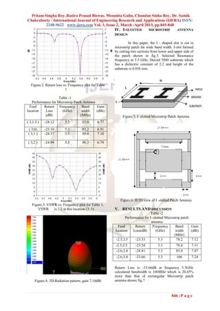
The document describes the design and simulation of a rectangular microstrip patch antenna and an I-slotted microstrip patch antenna for wireless communication. The rectangular antenna was designed to operate at 5.3 GHz but had a narrow bandwidth of 88 MHz and gain of 7.1 dBi. An I-slot was then cut into the patch to enhance the bandwidth and gain. The I-slotted antenna achieved a 20.45% increased bandwidth of 106 MHz and higher gain of 7.24 dBi at 5.3 GHz. Simulation results showed the I-slotted antenna had improved performance over the rectangular patch in terms of bandwidth, gain, voltage standing wave ratio, and efficiency. The enhanced antenna could potentially be useful for various


