
Recommended
More Related Content
What's hot
What's hot (20)
Similar to Efficiency by controlling modulation of actuators
Similar to Efficiency by controlling modulation of actuators (20)
More from Udhayakumar Venkataraman
More from Udhayakumar Venkataraman (20)
Recently uploaded
Recently uploaded (20)
Efficiency by controlling modulation of actuators
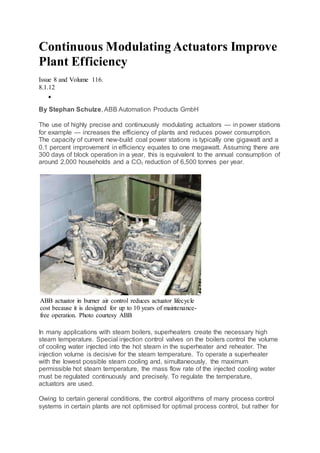
- 1. Continuous Modulating Actuators Improve Plant Efficiency Issue 8 and Volume 116. 8.1.12 By Stephan Schulze, ABB Automation Products GmbH The use of highly precise and continuously modulating actuators — in power stations for example — increases the efficiency of plants and reduces power consumption. The capacity of current new-build coal power stations is typically one gigawatt and a 0.1 percent improvement in efficiency equates to one megawatt. Assuming there are 300 days of block operation in a year, this is equivalent to the annual consumption of around 2,000 households and a CO2 reduction of 6,500 tonnes per year. ABB actuator in burner air control reduces actuator lifecycle cost because it is designed for up to 10 years of maintenance- free operation. Photo courtesy ABB In many applications with steam boilers, superheaters create the necessary high steam temperature. Special injection control valves on the boilers control the volume of cooling water injected into the hot steam in the superheater and reheater. The injection volume is decisive for the steam temperature. To operate a superheater with the lowest possible steam cooling and, simultaneously, the maximum permissible hot steam temperature, the mass flow rate of the injected cooling water must be regulated continuously and precisely. To regulate the temperature, actuators are used. Owing to certain general conditions, the control algorithms of many process control systems in certain plants are not optimised for optimal process control, but rather for
- 2. observing the permissible switching frequency and switch-on time of the drives technology used. This has negative consequences on the efficiency of the plant. After a brief introduction to actuator technology, this article describes an opportunity to improve the efficiency of steam power plants with continuously modulating actuators from ABB and, thereby, reduce operating costs. Actuators — the intelligent field devices Power station operators are keen to use automation technology to generate more energy and actuators play an important role in this, in systems and supply engineering and are used in almost all areas of industry. In the automation of processes, actuators regulate material, mass and energy flows by adjusting final control elements such as valves, flaps and cocks. The actuator and valve create a single unit — the control valve. The actuator normally comprises the motor and transmission as well as an output shaft or push rod and a position sensor. Actuators perform very different motion sequences, with a distinction made between actuators for linear motions and actuators for pivoting or rotating motions. The actuators are powered by pneumatic, hydraulic or electrical auxiliary energy. The actuator receives a control signal from the automation system, such as a control unit, operator station or process control system, which it must convert into a motion so that the control element of the actuating element, which can be the valve cone for example, assumes a corresponding position. With control valves, this is a stroke motion, whereas with flaps, ball cocks or rotary plug valves, this is a pivoting motion.
- 3. The positioner influences the auxiliary energy of the drive and in doing so, sets the desired setting of a control valve or maintains this despite external influences. In electrical drives, it is the power electronic circuits that control the run time and direction of rotation of the drive. Besides the motion type of electrical actuators, the duty/operation mode is also an important selection criterion. This raises the question of whether the final control element is to be used as a shut-off valve in open-close duty or whether it is to be run in positioning duty at intermediate positions or whether the final control element position is even to be adjusted at short intervals in a modulating duty in order to regulate the flow of a pipe, for example. These are decisive conditions for both the design of the final control element and also the actuator, as the loads in the various duties vary significantly. Accordingly, there are actuators for open-close duty, positioning duty, as well as actuators equipped for the high demands of modulating duty. In open-close duty, the final control element is activated relatively infrequently. There could be a few hours or even several months between two setting stages. In positioning duty, the final control element is moved to a defined intermediate position, e.g. to achieve a constant flow. Here, there are run-time restrictions, similar to those in open-close duty. In modulating duty, the actuating element must be frequently updated owing to ongoing changes in conditions. This is required in second intervals in sensitive control applications, which places demanding requirements on the actuator. The motor and mechanics must be designed so that the high number of switching operations can be sustained over long periods. The control accuracy must also remain consistent. An actuator must move a given load within a given time to a set position with a specific accuracy. The electric motors used in actuators normally work over a short term rather than in continuous operation and often have to meet particularly demanding requirements. These include a high accelerating and braking torque, a high holding torque at standstill, high speed rigidity, uniform rotation, a large speed control range, high efficiency, robustness, low maintenance costs, low noise and vibration and a high protection class. Often, the requirements contradict each other requiring compromises to be made in most cases. The right selection of actuators is of decisive significance for the function, investment, operating costs and reliability of the entire process technology. Contrac increases plant efficiency and lowers operating costs The efficiency of a plant is the relationship between power output and power input. The typical efficiency of a coal power station lies between 25% and 45%. The efficiency of a steam power plant increases with the temperature of the steam created in the power station boiler. However, permissible maximum temperature limits of the boiler tube material and a turbine to be exposed to the steam must not be exceeded. The more closely the temperature can be kept to its target value, the
- 4. closer the target value can be set to the permissible temperature limit. Thus, higher efficiency is achieved when operating the power plant. In many applications with steam boilers, superheaters create the necessary high steam temperature. The steam temperature must be controlled so that the permissible material temperatures of the steam turbine and boiler are not exceeded. The temperature is controlled via a steam cooler, which injects a specific volume of cooling water into the overheated steam flow. In a power station, there are two locations of use for steam coolers; the superheater and the reheater. The superheater cooling occurs before the steam is introduced into the high-pressure turbine. The reheater cooling is applied to the steam after the high-pressure turbine. This steam is reheated in the boiler before being fed to the medium-pressure or low- pressure turbine. The volume of the injection water is controlled via an external control valve. To achieve precise temperature control, the valve must respond quickly to downstream temperature changes and in order to cope with low flows and different load states it must also have a good control ratio. Decisive performance criteria include: precise control at a low flow rate and a high control ratio in order to keep the outlet temperature of the steam superheater constant; and a sufficient seating contact force to avoid leakage when starting up the plant and a rapid response to changes in steam temperature. Special injection valves are required for temperature control in the final stages of the superheater to dose the required cooling water. To operate a superheater with the lowest possible steam cooling and, simultaneously, the maximum permissible hot steam temperature, the mass flow rate of the injected cooling water must be regulated continuously and precisely. If too much water is injected, excessive steam cooling has adverse consequences for efficiency. Too little water results in excessive steam temperatures and pressures and creates a risk of damaging the superheater as well as the turbine and downstream components. The smallest volumes of water must be introduced. To achieve this requires highly precise positioning in a valve’s disproportionate zone. The actuator used therefore influences the efficiency of the plant. This must fulfil all requirements for the control of the injection valve. The permissible switching frequency of the installed electrical actuators is decisive for control accuracy and thus the turbine inlet temperature at the superheater. For safety reasons, a clearance is maintained between the steam temperature and the turbine limit temperature. If the differential temperature increases by 1°C, the overall plant efficiency reduces by up to 0.05%. Through precise control of the steam temperature, the plant can be operated very close to the turbine’s temperature limit, thus increasing efficiency. In a fossil-fuel 700-MW power plant, for example, a 1% efficiency increase translates into a profit of EUR 0.5 million per year. Typical current new-build coal power stations deliver an output of approx. 1100 MW and an improvement in efficiency of 0.1% is equivalent to an increased output of 1.1 MW. Electrical actuators must be serviced in accordance with load and switching frequency. An average switching frequency of fewer than 700 cycles per year produces a service interval of seven months. If the plant operator aims for longer service intervals, e.g. two years, this target will reduce the average permissible switching frequency to approx. 200 cycles per hour or approx. three cycles per minute.
- 5. ABB actuator in feedwater control application. Photo courtesy ABB Owing to these general conditions, the control algorithms of many process control systems are not optimised for optimal process control, but rather for observing the permissible switching frequency and switch-on time of the actuator technology used. This has negative consequences for plant efficiency. In contrast, an actuator that operates continuously in one process without restrictions on switching cycles and switching times, in the same way as an injection control valve for example, increases plant efficiency. Another important factor for power station operators is maintenance costs. These are even more important than the depreciable investment costs. The plant operator would like to use plant components with a life cycle that is as long as possible, in order avoid maintenance costs or potential downtime costs. However, extending service life normally entails comparably higher investment costs. The most important stage of a control valve from the plant operator’s perspective is its actual service life. Besides the operating costs incurred for energy and operating resources, it is servicing and maintenance costs that are the principal driving factors when it comes to life cycle costs. The cost behaviour means that, at a certain point in the utilisation phase of a device, the actuator with the higher acquisition costs amortises itself. This point of amortisation should be as close to the beginning of the utilisation phase as possible so that the plant operator can achieve a large saving potential and as a result, the logical decision is usually made to favour a more expensive actuator in terms of investment costs. Owing to the sliding motion, design factors dictate that worm gears wear more quickly than the spur gears of Contrac actuators. Servicing these actuators is extremely easy and economical as no transmission components have to be replaced. The transmission oil simply needs changing and the seal rings and gaskets replacing.
- 6. Contrac variable-speed actuators are designed for ten years of service-free continuous operation. The so-called service computer takes account of the load on the actuator, for example, evaluating temperatures, number of motor reversals and load peaks, and using these to calculate the remaining time until the next service is required. This load-dependent servicing facilitates optimal plant management when compared with time-based servicing. Despite the supposedly high investment costs, the linear and rotary actuators in the Contrac series represent the more economic solution when viewed over the entire service life. If you compare the life cycle costs of a Contrac that has been under constant load, with competitor products that have been subjected to relatively low loads, it can be seen that the putatively high initial investment amortises itself after just a few months and, at the longest, after four years. The Contrac series continuous electric variable-speed actuators are the ideal solution for highly precise, continuous position regulation of injection control valves and reduce operating costs. Actuators that regulate continuously and precisely The intelligent field devices of Contrac actuator systems are based upon ABB’s family of conventional rotary and linear actuators. The name Contrac is an amalgamation of the words ‘control’ and ‘actuator’. The actuator system sets itself apart with continuous positioning, precise control, long service intervals, overload protection in end positions without torque-dependent cut-off as well as its high protection class. The series comprises tried and tested mechanical components combined with microprocessor electronics and is compatible with fieldbuses as well as conventional control methods. The devices offer diagnostic options and parameter settings are performed via a graphic user interface. The systems are self- monitoring and offer fail-safe back-up of technical data. In the most frequently used duty, the Contrac actuator follows an analogue setpoint signal in continuous operation. As the torque or force increases or decreases smoothly, the mechanical components are not subjected to load peaks. This facilitates long service intervals and a long service life of the actuator and actuating element. In this material-friendly duty, Contrac systems can also be operated when control commands are received as pulses from a step controller. In this way, the user can benefit from these unique operating features even in older plants, which frequently still use step control or simple open-closed commands. Torques and forces can be set independently of each other as well as the direction of motion. This can either be set via a constant value or a torque/force characteristic curve. The speed settings are made in a similar manner. In the “Drive to end position” duty, individual settings are available for the respective end position. Depending on the settings, the motor either remains on or is switched off as soon as the actuator reaches its defined position and the brake is applied to stop the motor. With the help of the breakaway function, the Contrac actuator can make up to 200% of its rated torque or rated force available in the end position areas. This allows jammed actuating elements to be safely moved out of their end
- 7. position. For most control loops, minimal valve movements near the end position make little sense from a technical perspective. If, however, process variables change at this actuating element position, the actuator will follow the resulting control commands and there is a danger that the valve final control element will sustain permanent damage if it is approached too often. There is also a danger that valve positions very close to the end positions will cause cavitation. ABB actuators avoid this effect by defining a small area in front of the end position. As soon as the actuator reaches this area, it behaves as if it were set to ‘Drive to end position’. The three-phase asynchronous motor with cage rotor guarantees safe and reliable operation. The use of a frequency converter allows the torque and stroke time of the intelligent actuator to be varied. This means that both parameters can be adapted to the actuating element or process independently of each other. The motor is constantly under voltage, and increases or reduces the torque gently and in proportion to the control deviation. The actuator is always switched on, meaning that no restrictions are placed on the control loop, even at the maximum permissible ambient temperature. Where a state of balance exists, the drive force and process force are equivalent and the actuator will keep the actuating element in the required position. No temperature or torque monitoring switches are required. The devices have a very high overall efficiency level of 80 to 85 percent. They do not require any cooling period or reduction in switch-on time at high ambient temperatures. Owing to their 100% switch-on time, they are suited to highly-dynamic control loops, as required for highly-precise control loops for injection control valves or pressure-reducing stations. In rotary actuators, the motor drives a low-friction, oil-lubricated spur transmission. At the end of this spur transmission, a lever mounted on the output shaft transmits torque to the actuating element via a rod. As the position sensor is mounted directly on the rear end of the output shaft, position feedback can be provided without any backlash. This means Contrac is able to offer highly precise positioning.
- 8. Mounting the actuator on the final control element via a lever linkage has the advantage over direct drive that there is no direct heat transfer. This reduces the load on the actuator and facilitates longer service intervals. The design with lever/linkage bar assembly reduces servicing costs owing to the lower temperature loading. A specific lever length ratio between the actuator lever and final control element lever and optimisation of the angle in the lever linkage both increases the resulting torque at the final control element and allows the torque profile to be adapted to the final control element. The manufacturer offers the rotary actuators for rated torques from 50 to 16,000 Nm. The breakaway torque ranges from 200 to 32,000 Nm. The stroke time can be set between 10 and 900 seconds (at 90 degrees). Rotary actuators are used, for example, to activate multi-leaf dampers or regulate the mill air in cement works. In power plant technology, they are required to regulate the fuel volume, to control the flaps for the burner air or to optimise the fresh air or induced draught. ABB linear actuators feature a highly efficient ball roller spindle. The motor drives the spindle nut located on the thrust rod via a spur transmission, which then moves the thrust rod out or in, depending on the motor’s direction of rotation. The special feature of this rotary/linear conversion is a recirculating ball unit with extremely low friction. Integrated springs absorb any peak loads that may occur owing to kinetic energy when approaching the end positions of valves and also compensate for temperature-related alterations to the length of the thrust rod or valve stem that may occur when using the actuator on a superheated steam pipe. The linear actuators can be supplied with a rated actuating force of 2 to 100 kN and a breakaway force of 8 to 200 kN. The actuating speed can be set within a range of 0.1 to 10 mm per
- 9. second. These actuators are used in the most diverse applications, including injection control valves, drum level control valves, pressure reducing stations, feed water pre-heating, feed water control valves, bowl level control valve , minimum volume control valves or start-up control valves. Power control units are a central component of actuators. These can be installed in the field near the actuator or remotely in a mounting rack. An integrated version is available for the smallest rotary and linear actuators. In addition to the connection terminals, a microprocessor, a frequency converter for motor control, analogue and binary inputs and outputs, communication interfaces and a female connector for connection to a PC are also included. In order to be able to accurately position the actuating element, the power control adjusts the motor torque smoothly until an equilibrium of forces is achieved between the control actuator and final control elementfinal control element. High response sensitivity and positioning accuracy with short stroke times produce excellent control quality with long service life. The control concept sets the actuators apart from other manufacturers. A continuous positioner keeps the dead zone at +/- 0.05%. This precision facilitates highly precise positioning in the entire work area of each valve. The Contrac generation of actuators can be controlled by conventional signals. Users can retain their current system concept. However, they also have the facility to operate their plants with modern communication options at some point in the future in accordance with future concepts. The actuators communicate either through an RS232 interface, an FSK connection via the HART protocol or a profibus connection. A PC and the graphic user interface with the Contrac Device Type Manager (DTM) can be used to configure all actuator functions as well as to access diagnostics and service information. The software comprises two elements: the device software and the optional configuration software. The device software is loaded to the actuator electronic unit and contains the firmware, motor characteristics and software objects with the parameters relevant to the actuator, e. g. force/torque limits and start behaviour with and without breakaway. The DTM configuration software enables actuator data to be parameterised. The user also receives comprehensive diagnostics, service and maintenance information. The DTM can be loaded to a frame application, such as Smart Vision, which supports FDT/DTM technology. This enables it to be used either locally with the frame application or within a control system.
- 10. The components of a control valve are characterised by different service lives. Depending on the application, a component, and thus the entire system, can fail prematurely. A holistic asset management approach is essential to avoid such failure. The diagnostics function of Contrac variable-speed actuators enables predictive maintenance by monitoring the device itself. Some error patterns require detailed information to ascertain the precise cause. Contrac saves the parameters relating to service life (e.g. number of motor reversals, maximum temperature values for the transmission and electronics, peak loads and the dynamic loads to which the actuator has been exposed). The graphic user interface displays the saved data or the user can use this for evaluation at a later time. In order to establish the cause of non-reproducible errors, parameters relevant to the positioning loop (e.g. setpoint, actual position value, temperature and motor frequency) can be recorded during operation. Recordings can also be made over longer periods via the sample rate setting options. Conclusion In energy and steam creation, the regulation of certain plant components is influenced by the general conditions discussed, including defined service intervals or switch-on times of actuators. Highly precise and continuous regulation of plants can contribute to an increase in plant efficiency. In order to achieve this, actuators are used that are continuously regulated and have long service intervals. The higher investment costs for special variable-speed actuators are amortised within just a few months.
- 11. ABB’s Contrac actuators are the only variable-speed actuators on the market offering continuous regulation and high precision. The actuators set themselves apart with low life cycle costs and can also be used in areas with a high risk of explosion.