1. CHARLES ISIADINSO
GAS TURBINE
A gas turbine is an internal combustion engine that generates
power from gas spinning a turbine. The main goal of a gas turbine
is to pressurize air; this air then pushes the turbine, generating
energy.
Pressure is given as, 𝑃 =
𝑀
𝑉
. Therefore to increase pressure, we need
to decrease the volume without reducing the mass, increase the
mass without reducing the volume or increase both. Gas expands
when heated, therefore heating gas would lead to an increase in
mass and, assuming volume is constant, there would be an increase
in pressure. This is the fundamental principle behind a gas turbine.
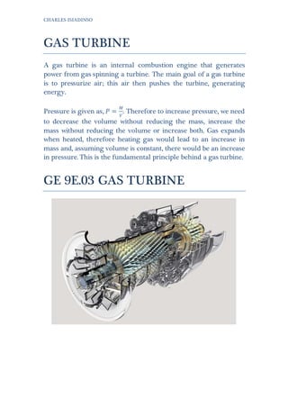
GE 9E.03 GAS TURBINE
2. CHARLES ISIADINSO
General Electric’s 9E.03 turbine is a heavy duty, 50Hz gas turbine
capable of producing 128MW of energy, in a simple cycle, and
193MW, in a combined cycle (see appendix B for a fully labeled
cross-sectional diagram of the 9E, containing all the parts and
components of the unit). The turbine has a low lifetime cost and
compact footprint, which makes it to plan into a plant layout. It can
run on natural gas, light and heavy distillate oils, naphtha, crude
oil, residual oil, blast furnace gas, syngas, or biofuels and can
switch between fuels while under load.
The 9E is designed with GE’s DLN (dry and low NOX) system,
which allows the 9E low NOX and CO emission when burning
natural gas (below 30mg/Nm3
15ppm and 30mg/Nm3
25ppm
respectively). The 9E also has high thermal efficiency, at 34% in a
simple cycle and 52% in a combined cycle.
The 9E produces heat at 10,100 Btu/kWh and 10,653 kJ/kWh, in a
simple cycle and 6,570 Btu/kWh and 6,930 kJ/kWh.
INTAKE:
Air enters the turbine through a weather case. The weather case
helps protect the filters from sun, rain and atmospheric
contaminants (e.g. debris). Inside the weather case are rows of self-
cleaning fillers, which clean the air. The filters are fitted with
differential pressure sensors, which give indication to the state of
the filters and whether they need cleaning. If the system detects
the filters are clogged, a contraflow stream of air is pushed
through the filters, one row at a time starting from the top.
Air leaving the filters, flows through a transition housing then
through silencing panels and finally through a system called the
inlet bleed heat module; here the air is heated to comply with
minimum compressor inlet temperature, especially in cool
weather. The inlet air flows down an air duct to the compressor.
COMPRESSION:
3. CHARLES ISIADINSO
At the entrance of the air compressor is a bell shaped object, which
allows smooth flow of air into the air compressor. As air enters the
compressor, it passes though variable inlet guide veins (IGVs),
which help regulate the airflow ensuring it is consistent and
reliable. The IGVs are controlled by an IGV actuator, which is
connected to a ring gear spanning the circumference of the
compressor. Each IGV sits on a pinion gear, which is meshed to the
ring gear, and thus, movement of the ring results in equal uniform
movement of all IGVs.
The 9E turbine compressor is a seventeen-stage axial flow system,
consisting of a set of rotation blades and stationary veins. One set
of rotating airfoil=shaped blades and set of stationary veins make
up a stage. The stages are numbered R0 to R17, for the rotating
blades and S0 to S17 for the stationary veins. Each stage is designed
to direct airflow to the next, including the IGVs. Compression
occurs as air flows through the compressor as rotating blades force
the air through progressively smaller spaces after each stage and,
as a result, temperature and pressure rises as the air progresses
through the compressor. The 9E, in a simple cycle, has a
compressor pressure ratio of 12.6:1, mass flow rate of 418kg/sec.
Air passes from the compressor to the compressor discharge
casing.
COMBUSTION:
4. CHARLES ISIADINSO
Air leaves the 9E’s compressor and flows into the combustion
chamber at approximately 13.8 bar (200 psig) and 700 degree
Fahrenheit. The 9E has 14 annular reverse flow combustion
chambers mounted on the compressor discharge case. To start the
combustion process, air from the compressor reverse flows into the
combustion chamber through the flow sleeve, the speed of the
compressed air is reduced to a velocity suitable for the combustor.
Primary air (air from the compressor) flows into the combustion
chamber via primary holes in the liner (a super alloy container,
inside the annular can, which contains the combustion process).
Fuel is injected, through the fuel injector, into the liner; the
primary air, flows over the dome and swirlers, which generate
turbulence in the primary airflow, rapidly mixing the air and fuel.
The 9E has only two spark plugs, two flame detectors and crossfire
tubes, connecting all 14 cans; these make up the system used to
burn the air-fuel mixture. An ignition in one of the chambers
causes a pressure rise, in that chamber, forcing hot gas through the
crossfire tubes propagating the flame. Secondary, cooling and
dilution air flow into the liner, through respective holes,
completing the combustion process.
5. CHARLES ISIADINSO
Hot gas leaves the cans and flows through a transition piece,
shaped to channel the hot gas to stage one of 9E three-stage high
energy-per-stage turbine. High temperature gas does work on the
turbines and, since a rigid shaft connects the compressor and
turbines, the work done on the turbine causes the compressor to
turn, thereby continuing the process. By adding another turbine,
the 9E is capable of driving a rotor, which can then be used to
generate power.
The turbine rotor section is made up of two wheel shafts (forward
and aft turbine wheel shafts), 3-stage turbine wheels (1st
, 2nd
and 3rd
stage turbine wheel assembly), with buckets, and two turbine
spacers. The forward wheel shaft extends from the compressor
discharge end through the 1st
stage turbine wheel to the 2nd
stage
turbine wheel. It also holds the number 2 bearing between the
compressor discharge case and the 1st
stage turbine. The aft wheel
connects the third stage turbine wheel to the load and holds the
number 3 bearing between the 3rd
stage wheel and the load.
6. CHARLES ISIADINSO
The turbine buckets are in direct contact with the high-velocity and
high temperature stream. The firing temperature (temperature at
which the stream hits the buckets), and pressure of the stream
determine the life span of the buckets for any bucket material.
Increased firing temperature results in increased performance
gains; however, the bucket material determines the maximum
allowable firing temperature. To tackle this, the buckets are made
of super alloys with very high melting points. The 1st
and 2nd
stage
buckets are also air cooled via cooling holes through the cross
section of the buckets to help tackle firing temperature restrictions;
3rd
stage buckets are not internally air-cooled. Integral shrouds and
fitted to the top of 2nd
and 3rd
stage buckets to provide damping
against vibrations.
7. CHARLES ISIADINSO
Gas from the nozzle applies a force on the buckets, which, in turn,
provides a torque to the rotor. The buckets are cooled with residual
air from the compressor.
EXHAUST:
The final stage of the process is emitting the exhaust fumes. Gas
from the turbines is directed into an axial or radial diffuser (radial
in the 9E), which carefully guides the gases out into a sound poof
chimney. Guide veins in the radial diffuser help direct the gases up
into the chimney.
A step-by-step view of how the turbine operates, from how it is
started, to how it is stopped, can be found in appendix A, Operating
Sequence of a Frame 6 GE Gas Turbine. The frame 6 is simply a
scaled down frame 9 (the class to which the 9E belongs) so there
aren’t any differences between the frame 6 operating sequence and
the frame 9 operating sequence. The only things different are
values like the operating speed, pre-determined fuel stroke
referencefiring, warming-up and acceleration rates.
8. CHARLES ISIADINSO
REFERENCE:
1. Brain, Marshall. "How Gas Turbine Engines Work” 01 April
2000. HowStuffWorks.com.
<http://science.howstuffworks.com/transport/flight/modern/tu
rbine.htm> [Accessed 16 June 2014]
2. Wikipedia contributors, 'Gas turbine', Wikipedia, The Free
Encyclopedia, 9 June 2014, 02:01 UTC,
<http://en.wikipedia.org/w/index.php?title=Gas_turbine&oldid
=612155202> [Accessed16 June 2014]
3. General Electric. "Heavy Duty Gas Turbine Products" June
2009. ge-energy.com. < http://www.ge-
energy.com/products_and_services/products/gas_turbines_hea
vy_duty/9e_heavy_duty_gas_turbine.jsp#> [Accessed17 June
2014]
4. GE Energy. 9E Gas Turbine Proven Performance for 50 Hz
Applications. 2009. Print.