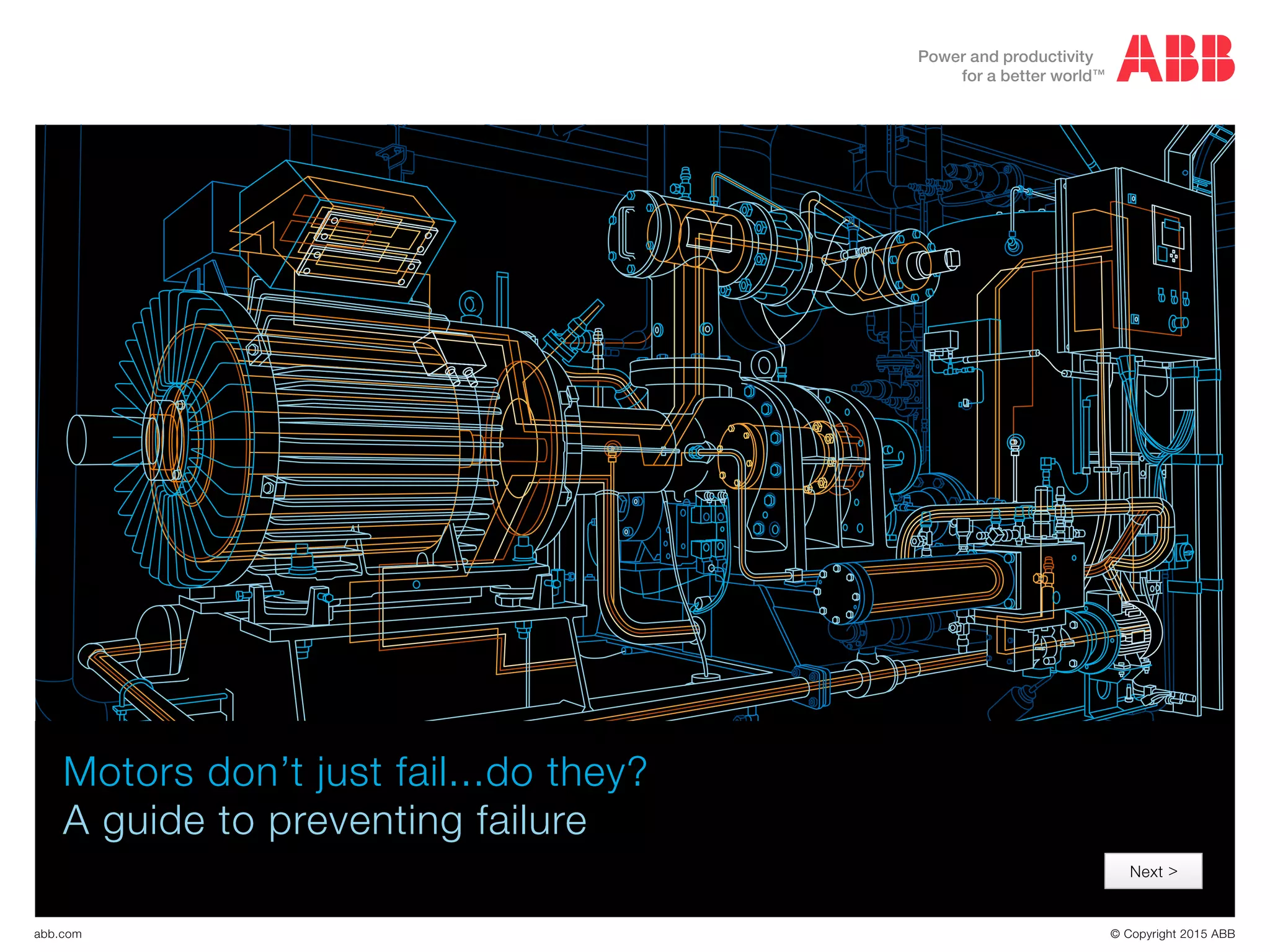
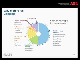
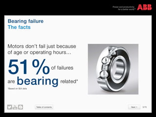
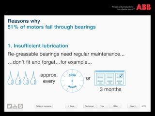
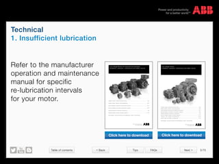
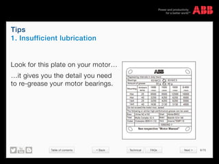
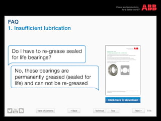
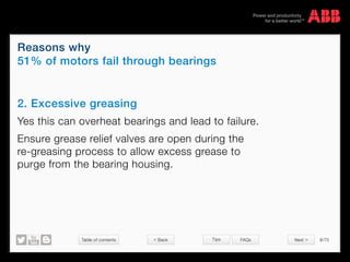
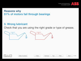
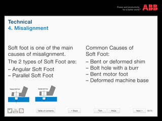
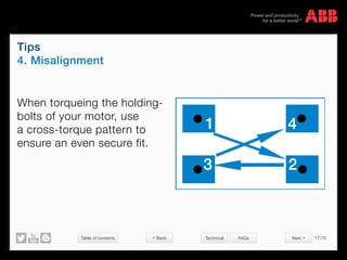
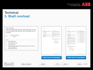
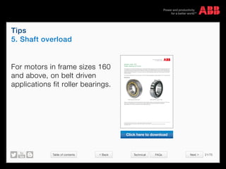
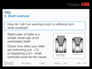
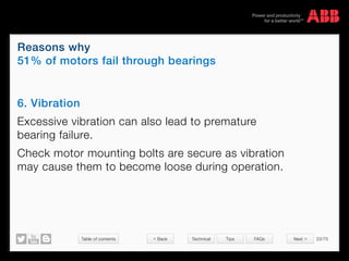
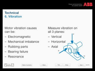
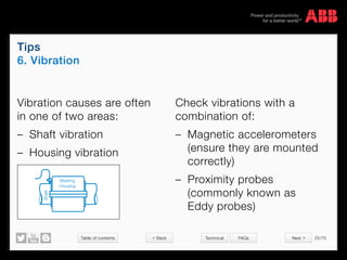
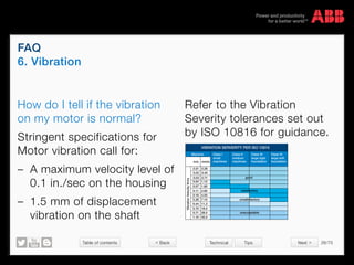
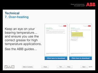
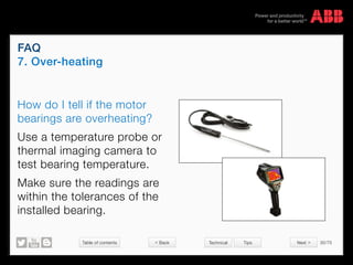
This document provides information on reasons why motors commonly fail, focusing on failures related to bearings. It states that 51% of motor failures are caused by bearings, and describes several common causes: insufficient lubrication, excessive greasing, wrong lubricant, misalignment, and shaft overload. It includes technical details, tips, and frequently asked questions about each cause to help users understand and prevent bearing failures in motors.
This PPT is based upon my training in Yokogawa Chennai.
Reference:
# Yokogawa Hand Book on CS 3000
# http://www.slideshare.net/bvent2005/dcs-presentation
This PPT is based upon my training in Yokogawa Chennai.
Reference:
# Yokogawa Hand Book on CS 3000
# http://www.slideshare.net/bvent2005/dcs-presentation
CENTUM VP is Yokogawaโs latest integrated production control system, also known as a distributed control system (DCS). Nearly 40 years of knowledge and experience with DCSs has gone into its development.
This presentation explains various parameters used in AC drive of Allen Bradley Model Powerflex 4M
Unlock full featured course with 100+ Video Lectures at 30% Discount on "Advanced AC Drive- VFD, Stepper and Servo Drives" lifetime E-Learning course for 39 USD only: https://www.udemy.com/learn-vfd-in-a-day/?couponCode=slideshare2016
Enroll for Advanced Industrial Automation Training with PLC, HMI and Drive Combo with 300+ Video Lecture for 69.3 USD only: http://online.nfiautomation.org/catalog/1769?couponCode=LEARNING_MADE_EASY
Final project report on grocery store management system..pdfKamal Acharya
ย
In todayโs fast-changing business environment, itโs extremely important to be able to respond to client needs in the most effective and timely manner. If your customers wish to see your business online and have instant access to your products or services.
Online Grocery Store is an e-commerce website, which retails various grocery products. This project allows viewing various products available enables registered users to purchase desired products instantly using Paytm, UPI payment processor (Instant Pay) and also can place order by using Cash on Delivery (Pay Later) option. This project provides an easy access to Administrators and Managers to view orders placed using Pay Later and Instant Pay options.
In order to develop an e-commerce website, a number of Technologies must be studied and understood. These include multi-tiered architecture, server and client-side scripting techniques, implementation technologies, programming language (such as PHP, HTML, CSS, JavaScript) and MySQL relational databases. This is a project with the objective to develop a basic website where a consumer is provided with a shopping cart website and also to know about the technologies used to develop such a website.
This document will discuss each of the underlying technologies to create and implement an e- commerce website.
Welcome to WIPAC Monthly the magazine brought to you by the LinkedIn Group Water Industry Process Automation & Control.
In this month's edition, along with this month's industry news to celebrate the 13 years since the group was created we have articles including
A case study of the used of Advanced Process Control at the Wastewater Treatment works at Lleida in Spain
A look back on an article on smart wastewater networks in order to see how the industry has measured up in the interim around the adoption of Digital Transformation in the Water Industry.
CFD Simulation of By-pass Flow in a HRSG module by R&R Consult.pptxR&R Consult
ย
CFD analysis is incredibly effective at solving mysteries and improving the performance of complex systems!
Here's a great example: At a large natural gas-fired power plant, where they use waste heat to generate steam and energy, they were puzzled that their boiler wasn't producing as much steam as expected.
R&R and Tetra Engineering Group Inc. were asked to solve the issue with reduced steam production.
An inspection had shown that a significant amount of hot flue gas was bypassing the boiler tubes, where the heat was supposed to be transferred.
R&R Consult conducted a CFD analysis, which revealed that 6.3% of the flue gas was bypassing the boiler tubes without transferring heat. The analysis also showed that the flue gas was instead being directed along the sides of the boiler and between the modules that were supposed to capture the heat. This was the cause of the reduced performance.
Based on our results, Tetra Engineering installed covering plates to reduce the bypass flow. This improved the boiler's performance and increased electricity production.
It is always satisfying when we can help solve complex challenges like this. Do your systems also need a check-up or optimization? Give us a call!
Work done in cooperation with James Malloy and David Moelling from Tetra Engineering.
More examples of our work https://www.r-r-consult.dk/en/cases-en/
Hybrid optimization of pumped hydro system and solar- Engr. Abdul-Azeez.pdffxintegritypublishin
ย
Advancements in technology unveil a myriad of electrical and electronic breakthroughs geared towards efficiently harnessing limited resources to meet human energy demands. The optimization of hybrid solar PV panels and pumped hydro energy supply systems plays a pivotal role in utilizing natural resources effectively. This initiative not only benefits humanity but also fosters environmental sustainability. The study investigated the design optimization of these hybrid systems, focusing on understanding solar radiation patterns, identifying geographical influences on solar radiation, formulating a mathematical model for system optimization, and determining the optimal configuration of PV panels and pumped hydro storage. Through a comparative analysis approach and eight weeks of data collection, the study addressed key research questions related to solar radiation patterns and optimal system design. The findings highlighted regions with heightened solar radiation levels, showcasing substantial potential for power generation and emphasizing the system's efficiency. Optimizing system design significantly boosted power generation, promoted renewable energy utilization, and enhanced energy storage capacity. The study underscored the benefits of optimizing hybrid solar PV panels and pumped hydro energy supply systems for sustainable energy usage. Optimizing the design of solar PV panels and pumped hydro energy supply systems as examined across diverse climatic conditions in a developing country, not only enhances power generation but also improves the integration of renewable energy sources and boosts energy storage capacities, particularly beneficial for less economically prosperous regions. Additionally, the study provides valuable insights for advancing energy research in economically viable areas. Recommendations included conducting site-specific assessments, utilizing advanced modeling tools, implementing regular maintenance protocols, and enhancing communication among system components.
Cosmetic shop management system project report.pdfKamal Acharya
ย
Buying new cosmetic products is difficult. It can even be scary for those who have sensitive skin and are prone to skin trouble. The information needed to alleviate this problem is on the back of each product, but it's thought to interpret those ingredient lists unless you have a background in chemistry.
Instead of buying and hoping for the best, we can use data science to help us predict which products may be good fits for us. It includes various function programs to do the above mentioned tasks.
Data file handling has been effectively used in the program.
The automated cosmetic shop management system should deal with the automation of general workflow and administration process of the shop. The main processes of the system focus on customer's request where the system is able to search the most appropriate products and deliver it to the customers. It should help the employees to quickly identify the list of cosmetic product that have reached the minimum quantity and also keep a track of expired date for each cosmetic product. It should help the employees to find the rack number in which the product is placed.It is also Faster and more efficient way.
Industrial Training at Shahjalal Fertilizer Company Limited (SFCL)MdTanvirMahtab2
ย
This presentation is about the working procedure of Shahjalal Fertilizer Company Limited (SFCL). A Govt. owned Company of Bangladesh Chemical Industries Corporation under Ministry of Industries.
Student information management system project report ii.pdfKamal Acharya
ย
Our project explains about the student management. This project mainly explains the various actions related to student details. This project shows some ease in adding, editing and deleting the student details. It also provides a less time consuming process for viewing, adding, editing and deleting the marks of the students.
Nuclear Power Economics and Structuring 2024Massimo Talia
ย
Title: Nuclear Power Economics and Structuring - 2024 Edition
Produced by: World Nuclear Association Published: April 2024
Report No. 2024/001
ยฉ 2024 World Nuclear Association.
Registered in England and Wales, company number 01215741
This report reflects the views
of industry experts but does not
necessarily represent those
of World Nuclear Associationโs
individual member organizations.
1. A guide to preventing failure
Motors donโt just fail...do they?
ยฉ Copyright 2015 ABBabb.com
Next >
2. ยฉ Copyright 2015 ABBabb.com
2/70
Why motors fail
Contents
Click on your topic
to discover more
10% Others
51% fail through
bearings
1. Insufficient lubrication
2. Excessive greasing
3. Wrong lubricant
4. Misalignment
5. Shaft overload
6. Vibration
7. Over heating16% Stator
winding
1. Over heating
2. Over loading
16% External
conditions
1. Heat
2. Humidity
3. Contamination
4. High ambient
5% Rotor bar
1. Starting frequency
2. Overloads
3. Under voltage
2% Shaft coupling
1. Misalignment
2. Bad installation
3. Table of contents 3/70
ยฉ Copyright 2015 ABBabb.com
Bearing failure
The facts
Motors donโt fail just because
of age or operating hoursโฆ
51%of failures
are bearing related*
*Based on IEA data
Next >
4. Table of contents 4/70
ยฉ Copyright 2015 ABBabb.com
Reasons why
51% of motors fail through bearings
Technical Tips FAQs
1. Insufficient lubrication
Re-greasable bearings need regular maintenance...
โฆdonโt fit and forgetโฆfor example...
2000
hours
โ
JAN FEB MAR
3 months
or
approx.
every
< Back Next >
5. Table of contents 5/70
ยฉ Copyright 2015 ABBabb.com
Technical
1. Insufficient lubrication
Tips FAQs
Refer to the manufacturer
operation and maintenance
manual for specific
re-lubrication intervals
for your motor.
Low voltage Motors for explosive atmospheres
Installation, operation, maintenance and safety manual
Installation, operation, maintenance and safety manual ............................................................................................. EN 3
Montage-, Betriebs-, Wartungs- und Sicherheitsanleitung ....................................................................................... DE 27
Manuel dโinstallation, dโexploitation, de maintenance et de sรฉcuritรฉ ........................................................................ FR 51
Manual de instalaciรณn, funcionamiento, mantenimiento y seguridad ........................................................................ ES 75
Manuale dโinstallazione, funzionamento e manutenzione ........................................................................................... IT 99
Manual de instalaรงรฃo, operaรงรฃo, manutenรงรฃo e seguranรงa ................................................................................... PT 123
More languages โ see web site www.abb.com/motors&generators > Motors > Document library
Low voltage motors
Installation, operation, maintenance and safety manual
Installation, operation, maintenance and safety manual............................................................................................ EN 3
Montage-, Betriebs-, Wartungs- und Sicherheitsanleitung...................................................................................... DE 21
Manuel dโinstallation, dโexploitation, de maintenance et de sรฉcuritรฉ ....................................................................... FR 41
Manual de instalaciรณn, funcionamiento, mantenimiento y seguridad ....................................................................... ES 61
Manuale dโinstallazione, funzionamento e manutenzione..........................................................................................IT 81
Manual de instalaรงรฃo, operaรงรฃo, manutenรงรฃo e seguranรงa ..................................................................................PT 101
Installations-, driffts-, underhรฅlls- och sรคkerhetsmanual ....................................................................................... SV 123
Asennus-, kรคyttรถ-, kunnossapito- ja turvallisuusohje.............................................................................................. FI 141
More languages โ see web site www.abb.com/motors&generators > Motors > Document library
Click here to download Click here to download
< Back Next >
6. Table of contents 6/70
ยฉ Copyright 2015 ABBabb.com
Tips
1. Insufficient lubrication
Technical FAQs
Look for this plate on your motorโฆ
โฆit gives you the detail you need
to re-grease your motor bearings.
Next >< Back
7. Table of contents 7/70
ยฉ Copyright 2015 ABBabb.com
FAQ
1. Insufficient lubrication
Technical Tips
Do I have to re-grease sealed
for life bearings?
No, these bearings are
permanently greased (sealed for
life) and can not be re-greased
We reserve all rights in this document and in the subject matter and illustrations contained therein.
Any reproduction, disclosure to third parties or utilization of its contents โ in whole or in parts โ is forbidden without prior written consent of ABB.
Copyrightยฉ 2014 ABB
Document kind Document identity Revision
Technical description 3GZF500930-344 A
Owner organization Document type Date of revision (yyyy-mm-dd) Status Page(s)
PG IEC LV MOTORS Variant code description 2012-03-09 Valid 1(1)
Department Prepared by Approved by Security level
MLD200 Juha Huhtamรคki Patrik Norrgรฅrd Internal
We reserve all rights in this document and in the information contained therein. Reproduction, use or disclosure to third parties without express authority is strictly forbidden.
ยฉ Copyright 2007 ABB
Variant code: 194
2Z bearings greased for life at both ends.
x = Available, s = Standard feature
This code includes bearings greased for life in both D- and ND-End of the motor.
A grease for life bearing means that the grease and balls of the bearing are encapsulated and the bearing canโt
be re-greased.
The 2Z bearings are closed by a metal shield on both sides of the bearing (see picture below).
The double side shield design protects against entry of dirt and particles and keeps the grease in the bearing.
Other types of grease for life bearings are 2RS bearings that are protected with a rubber seal instead of metal
shields.
If a bearing is of 1Z type itโs only sealed on one side, and the same goes for 1RS bearings.
56 63 71 80 90 100 112 132 160 180 200 225 250 280 315 355 400 450
M3BP s s s s s s x x x x x
M3AA s s s s s s s s s s s s x
M2BA s s s s s s s s s s s s
M2AA s s s s s s s s s s s s s
Picture of bearing with shields (2Z)
Variant code: 194
2Z bearings greased for life at both ends.
This includes bearings greased for life in both the drive and non-drive end of the motor.
A grease for life bearing means that the grease and rolling elements of the bearing are encapsulated and the bearing
canโt be re-greased.
The 2Z bearings are closed by a metal shield on both sides of the bearing (see picture below).
The double side shield design protects against entry of dirt and particles and keeps the grease in the bearing.
Other types of greased for life bearings are 2RS bearings that are protected with rubber seals instead of metal shields.
If a bearing with a suffix of 1Z is only sealed on one side, and the applies to 1RS bearings.
Picture of bearing with shields (2Z)
Document kind Document identity Revision
Technical description 3GZF500930-344 A
Owner organization Document type Date of revision (yyyy-mm-dd) Status Page(s)
PG IEC LV MOTORS Variant code description 2012-03-09 Valid 1(1)
Department Prepared by Approved by Security level
MLD200 Juha Huhtamรคki Patrik Norrgรฅrd Internal
We reserve all rights in this document and in the information contained therein. Reproduction, use or disclosure to third parties without express authority is strictly forbidden.
ยฉ Copyright 2007 ABB
Variant code: 194
2Z bearings greased for life at both ends.
x = Available, s = Standard feature
This code includes bearings greased for life in both D- and ND-End of the motor.
A grease for life bearing means that the grease and balls of the bearing are encapsulated and the bearing canโt
be re-greased.
The 2Z bearings are closed by a metal shield on both sides of the bearing (see picture below).
The double side shield design protects against entry of dirt and particles and keeps the grease in the bearing.
Other types of grease for life bearings are 2RS bearings that are protected with a rubber seal instead of metal
shields.
If a bearing is of 1Z type itโs only sealed on one side, and the same goes for 1RS bearings.
56 63 71 80 90 100 112 132 160 180 200 225 250 280 315 355 400 450
M3BP s s s s s s x x x x x
M3AA s s s s s s s s s s s s x
M2BA s s s s s s s s s s s s
M2AA s s s s s s s s s s s s s
Picture of bearing with shields (2Z)
Click here to download
< Back Next >
8. Table of contents 8/70
ยฉ Copyright 2015 ABBabb.com
Reasons why
51% of motors fail through bearings
Tips FAQs
2. Excessive greasing
Yes this can overheat bearings and lead to failure.
Ensure grease relief valves are open during the
re-greasing process to allow excess grease to
purge from the bearing housing.
< Back Next >
9. Table of contents 9/70
ยฉ Copyright 2015 ABBabb.com
Tips
2. Excessive greasing
FAQs
A bearing lip seal will typically fail at 500 psi,
yet grease guns can produce up to 1500 psi
Add each shot of grease slowly
to avoid pressure build-up
< Back Next >
10. Table of contents 10/70
ยฉ Copyright 2015 ABBabb.com
FAQ
2. Excessive greasing
Tips
What is the best way to control over-greasing?
1. Always make sure relief valves are cleaned out of any dirt or
hardened grease
2. Remove grease outlet plug or open outlet valve where fitted
3. Slowly pump grease into the bearings every few seconds
(avoid quick-lever actions as pressure will build and
damage seals)
4. Discontinue greasing if any abnormal back pressure is felt
Back Next
11. Table of contents 11/70
ยฉ Copyright 2015 ABBabb.com
Reasons why
51% of motors fail through bearings
Technical Tips FAQs
3. Wrong lubricant
Check that you are using the right grade or type of grease.
Back Next
12. Table of contents 12/70
ยฉ Copyright 2015 ABBabb.com
Technical
3. Wrong lubricant
Tips FAQs
When re-greasing, use only special
ball bearing grease with the following
properties:
โ Good quality grease with lithium
complex soap and with mineral or
PAO-oil
โ Base oil viscosity 100-160 cST at 40ยฐC
โ Consistency NLGI grade 1.5 - 3
โ Temperature range -30ยฐC - +120ยฐC,
continuously.
6.2.4 Lubricants
WARNING
Do not mix different types of grease.
Incompatible lubricants may cause bearing damage.
When regreasing, use only special ball bearing grease with
the following properties:
โ good quality grease with lithium complex soap and with
mineral- or PAO-oil
โ base oil viscosity 100-160 cST at 40ยฐC
โ consistency NLGI grade 1.5 - 3 *)
โ temperature range -30ยฐC - +120ยฐC, continuously.
*) For vertical mounted motors or in hot conditions a stiffer
end of scale is recommended.
The above mentioned grease specification is valid if the
ambient temperature is above -30ยฐC or below +55ยฐC, and
the bearing temperature is below 110ยฐC; otherwise consult
ABB regarding suitable grease.
Grease with the correct properties is available from all the
major lubricant manufacturers.
Admixtures are recommended, but a written guarantee
must be obtained from the lubricant manufacturer,
especially concerning EP admixtures, that admixtures do
not damage bearings or the properties of lubricants at the
operating temperature range.
WARNING
Lubricants containing EP admixtures are not
recommended in high bearing temperatures in frame
sizes 280 to 450.
The following high performance greases can be used:
- Esso Unirex N2 or N3 (lithium complex base)
- Mobil Mobilith SHC 100 (lithium complex base)
- Shell Gadus S5 V 100 2 (lithium complex base)
- Klรผber Klรผberplex BEM 41-132 (special lithium
base)
- FAG Arcanol TEMP110 (lithium complex base)
- Lubcon Turmogrease L 802 EP PLUS
(special lithium base)
- Total Multiplex S 2 A (lithium complex base)
NOTE!
Always use high speed grease for high speed 2-pole
machines where the speed factor is higher than
480,000 (calculated as Dm x n where Dm = average
bearing diameter, mm; n = rotational speed, r/min).
The high speed grease is also used in motor types
M2CA, M2FA, M2CG and M2FG, frame sizes 355 to
400 2-pole machines.
The following greases can be used for high speed cast iron
motors but not mixed with lithium complex greases:
- Klรผber Klรผber Quiet BQH 72-102 (polyurea base)
- Lubcon Turmogrease PU703 (polyurea base)
If other lubricants are used;
Check with the manufacturer that the qualities correspond
to those of the above mentioned lubricants. The lubrication
interval are based on the listed high performance greases
above. Using other greases can reduce the interval.
If the compatibility of the lubricant is uncertain, contact
ABB.
Low voltage motor manual 01-2009 | ABB Motors and Generators EN-17
Refer to the lubricants section of your
motor operations manual.
Click here to download
Back Next
13. Table of contents 13/70
ยฉ Copyright 2015 ABBabb.com
Tips
3. Wrong lubricant
Technical FAQs
Do not mix different types of grease.
Incompatible lubricants may cause bearing damage.
Back Next
14. Table of contents 14/70
ยฉ Copyright 2015 ABBabb.com
FAQ
3. Wrong lubricant
Technical Tips
Are there any specific greases I need
to use in specific applications?
Yes, there are specific greases you need to use for
say high temperature or hygienic applicationsโฆ.
โฆrefer to the lubricants section of your motor
operation manual.
Back Next
15. Table of contents 15/70
ยฉ Copyright 2015 ABBabb.com
Reasons why
51% of motors fail through bearings
Technical Tips FAQs
4. Misalignment
Itโs essential that the motor and load be
correctly aligned under actual operating
temperatures and conditions. Machines
that are correctly aligned at room
temperature may become badly misaligned
due to deformation or different thermal
growth associated with temperature
change. The alignment must be checked,
and corrected, if necessary, after the
motor and driven machine have reached
their maximum temperature under load.
โ
โ
Back Next
16. Table of contents 16/70
ยฉ Copyright 2015 ABBabb.com
Technical
4. Misalignment
Tips FAQs
Soft foot is one of the main
causes of misalignment.
The 2 types of Soft Foot are:
โ Angular Soft Foot
โ Parallel Soft Foot
Common Causes of
Soft Foot:
โ Bent or deformed shim
โ Bolt hole with a burr
โ Bent motor foot
โ Deformed machine base
Parallel Soft FootAngular Soft Foot
Back Next
17. Table of contents 17/70
ยฉ Copyright 2015 ABBabb.com
Tips
4. Misalignment
Technical FAQs
When torqueing the holding-
bolts of your motor, use
a cross-torque pattern to
ensure an even secure fit.
1 4
23
Back Next
18. Table of contents 18/70
ยฉ Copyright 2015 ABBabb.com
FAQ
4. Misalignment
Technical Tips
How often should I check the alignment of a motor?
ABB technicians recommend a motor should be
checked approximately every 2,000 hours.
Both operating and non-operating alignment
should be checked.
Back Next
19. Table of contents 19/70
ยฉ Copyright 2015 ABBabb.com
Reasons why
51% of motors fail through bearings
Technical Tips FAQs
5. Shaft overload
Excessive loading through the shaft of your motor may
cause failure.
Belt driven pulleys often put high load directly onto the
shaft bearing.
Back Next
20. Table of contents 20/70
ยฉ Copyright 2015 ABBabb.com
Technical
5. Shaft overload
Tips FAQs
Radial forces
Pulley diameter
When the desired bearing life has been determined the mini-
mum permissible pulley diameter can be calculated with FR,
according to the formula:
Where:
D: pulley diameter, mm
P: power requirement, kW
n: motor speed, r/min.
K: belt tension factor, dependent on belt type and type of duty. A common
value for V-belts is 2.5
FR
: permissible radial force
D =
1.9 โข 107
โข K โข P
n โข FR
Permissible loading on shaft
The tables give the permissible radial force in Newtons, as-
suming zero axial force, ambient temperature of 25ยฐC.
Permissible loads of simultaneous radial and axial forces will
be supplied on request.
The bearing life, L10
, is calculated according to SKFโs theory
on bearing life L10aah
, which also takes the purity of the grease
into consideration. An adequate lubrication is a necessary
prerequisite for the table at right.
If the radial force is applied between points X0
and Xmax
, the
permissible force FR
can be calculated from the following
formula:
FR
= FX0
-
X
(FX0
- FXmax
)
E
M000021
Where:
E: length of the shaft extension in the standard version
ABB Motors and Generators | 9AKK105944 EN 06-2013 99
Radial forces
Pulley diameter
When the desired bearing life has been determined, the mini-
mum permissible pulley diameter can be calculated with FR
as follows:
D =
1.9 โข 107
โข K โข P
n โข FR
Where:
D: pulley diameter, mm
P: power requirement, kW
n: motor speed, r/min.
K: belt tension factor, dependent on belt type and type of duty. A common
value for V-belts is 2.5
FR
: permissible radial force
Permissible loading on the shaft
The following table shows permissible radial forces on the
shaft in Newtons, assuming zero axial force, a 25 ยฐC ambi-
ent temperature, and normal conditions. The values are given
for a calculated bearing life of 20 000 and 40 000 hours per
motor size.
These calculated values further assume mounting position
IM B3 (foot-mounted), with force directed sideways. In some
cases, the strength of the shaft affects permissible forces.
Permissible loads of simultaneous radial and axial forces can
be supplied on request.
If the radial force is applied between points X0 and Xmax,
the permissible force FR can be calculated with the following
formula:
FR
= FX0
-
X
(FX0
- FXmax
)
E
Where:
E: length of the shaft extension in the standard version
Motor
size
No. of
poles
Length
of shaft
extension
E (mm)
Basic design with deep groove ball bearings
20,000 h 40,000 h
FXo
(N) FXmax
(N) FXo
(N) FXmax
(N)
71 2 30 540 460 370 310
4 30 680 580 540 455
6 30 780 655 620 525
8 30 860 655 680 580
80 2 40 735 620 585 490
4 40 925 780 735 615
6 40 1060 865 840 710
8 40 1165 870 925 780
90 2 50 805 660 590 485
4 50 1015 835 805 660
6 50 1160 955 920 760
8 50 1280 1050 1015 835
100 2 60 860 695 365 295
4 60 1410 1135 860 695
6 60 1615 1300 1215 975
8 60 1780 1430 1410 1135
112 2 60 870 715 365 300
4 60 1425 1165 870 710
6 60 1635 1335 1230 1005
8 60 1800 1470 1425 1165
132 2 80 1720 1400 890 725
4 80 2320 1890 1720 1400
6 80 2655 2160 2105 1715
8 80 2925 2380 2320 1890
M000021
Permissible radial forces, motor sizes 71 โ 132
ABB Motors and Generators | 9AKK105944 EN 06-2013 41
Radial forces
Pulley diameter
When the desired bearing life has been determined, the mini-
mum permissible pulley diameter can be calculated with FR
as follows:
D =
1.9 โข 107
โข K โข P
n โข FR
Where:
D: pulley diameter, mm
P: power requirement, kW
n: motor speed, r/min.
K: belt tension factor, dependent on belt type and type of duty. A common
value for V-belts is 2.5
FR
: permissible radial force
Permissible loading on the shaft
The following table shows permissible radial forces on the
shaft in Newtons, assuming zero axial force, a 25 ยฐC ambi-
ent temperature, and normal conditions. The values are given
for a calculated bearing life of 20 000 and 40 000 hours per
motor size.
These calculated values further assume mounting position
IM B3 (foot-mounted), with force directed sideways. In some
cases, the strength of the shaft affects permissible forces.
Permissible loads of simultaneous radial and axial forces can
Motor
size
No. of
poles
Length
of shaft
extension
E (mm)
Basic design with deep groove ball bearings
20,000 h 40,000 h
FXo
(N) FXmax
(N) FXo
(N) FXmax
(N)
71 2 30 540 460 370 310
4 30 680 580 540 455
6 30 780 655 620 525
8 30 860 655 680 580
80 2 40 735 620 585 490
4 40 925 780 735 615
6 40 1060 865 840 710
8 40 1165 870 925 780
90 2 50 805 660 590 485
4 50 1015 835 805 660
6 50 1160 955 920 760
8 50 1280 1050 1015 835
100 2 60 860 695 365 295
4 60 1410 1135 860 695
6 60 1615 1300 1215 975
8 60 1780 1430 1410 1135
112 2 60 870 715 365 300
4 60 1425 1165 870 710
6 60 1635 1335 1230 1005
8 60 1800 1470 1425 1165
132 2 80 1720 1400 890 725
4 80 2320 1890 1720 1400
6 80 2655 2160 2105 1715
8 80 2925 2380 2320 1890
Permissible radial forces, motor sizes 71 โ 132
Click here to download Click here to download
Back Next
21. Table of contents 21/70
ยฉ Copyright 2015 ABBabb.com
Tips
5. Shaft overload
Technical FAQs
For motors in frame sizes 160
and above, on belt driven
applications fit roller bearings.
Document kind Document identity Revision
Technical description 3GZF500930-129 B
Owner organization Document type Date of revision (yyyy-mm-dd) Status Page(s)
PG IEC LV MOTORS Variant code description 2013-05-20 Valid 1(1)
Department Prepared by Approved by Security level
MLD200 Juha Huhtamรคki Patrik Norrgรฅrd Internal
We reserve all rights in this document and in the information contained therein. Reproduction, use or disclosure to third parties without express authority is strictly forbidden.
ร Copyright 2007 ABB
Variant code: 037
Roller bearing at D-end.
x = Available, s = Standard feature
This code changes the drive end ball bearing to a roller bearing. Roller bearings are accommodated to high radial
forces e.g. belt drives. Roller bearings do not withstand axial forces at all and in vertical application it might
require special bearing arrangements also for the non-drive end. Please check also if the shaft end dimension is
suitable for the stress generated by the radial force, this can be done with the software program Bearings
(included in DriveSize).
This code includes VC036 (transport lock for bearing) and VC041 (bearings regreasable via grease nipples)
on 160 โ 450 frame sizes.
NOTE!
In sizes 071-132 this code includes VC036 but not VC041, we only fill up the NU bearing with grease.
Roller bearing with brass holder Roller bearing with polymer holder
Pictures of roller bearings, with brass holder (left) and polymer holder at (right). As the bearing consists of an
outer ring, an inner ring and rollers between them the surface to carry radial load is large compared to ball
bearings but no surface to carry axial force.
56 63 71 80 90 100 112 132 160 180 200 225 250 280 315 355 400 450
M3BP x x x x x x x x x x x x x x x x
M3AA x x x x x x x x x x
M2BA x x x x x x x x
M2AA x x x x x
Roller Bearing
Roller bearing with brass holder Roller bearing with polymer holder
Pictures of roller bearings, with brass holder (left) and polymer holder at (right). As a roller bearing is made up of an inner ring,
outer ring and rolling elements in a holder they have a larger radial load carrying area compared to ball bearings.
Roller bearings do not have a surface area to accommodate axial forces.
We reserve all rights in this document and in the subject matter and illustrations contained therein.
Any reproduction, disclosure to third parties or utilization of its contents โ in whole or in parts โ is forbidden without prior written consent of ABB.
Copyrightยฉ 2014 ABB
Variant code: 037
Roller bearing at D-end.
This changes the drive end (D-end) ball bearing to a roller bearing. Roller bearings are used to accommodate high radial forces
on applications such as belt drives. Roller bearings are not able to accommodate axial forces and in vertical applications may
require special bearings to be fitted to the non-drive end. The shaft must also be checked to ensure that it is can cope with the
radial forces that will be applied to it. This check can be done using the Bearings program that comes included with the ABB
DriveSize software.
This includes VC036 (transport lock for bearing) and VC041 (bearings regreasable via grease nipples) on 160 โ 450 frame sizes.
Roller Bearing
Click here to download
Back Next
22. Table of contents 22/70
ยฉ Copyright 2015 ABBabb.com
FAQ
5. Shaft overload
Technical Tips
Rapid wear of belts is a
simple visual sign of an
overloaded shaft.
Check how often your belts
are bottoming out - if it
is happening a lot โ shaft
overload could be the cause.
Correct position
of belt in pulley
Bottomed out
Back Next
How do I tell if an existing motor is suffering from
shaft overload?
23. Table of contents 23/70
ยฉ Copyright 2015 ABBabb.com
Reasons why
51% of motors fail through bearings
Technical Tips FAQs
6. Vibration
Excessive vibration can also lead to premature
bearing failure.
Check motor mounting bolts are secure as vibration
may cause them to become loose during operation.
Back Next
24. Table of contents 24/70
ยฉ Copyright 2015 ABBabb.com
Technical
6. Vibration
Tips FAQs
Motor vibration causes
can be:
โ Electromagnetic
โ Mechanical imbalance
โ Rubbing parts
โ Bearing failure
โ Resonance
V
H
A
Measure vibration on
all 3 planes:
โ Vertical
โ Horizontal
โ Axial
Back Next
25. Table of contents 25/70
ยฉ Copyright 2015 ABBabb.com
Tips
6. Vibration
Technical FAQs
Vibration causes are often
in one of two areas:
โ Shaft vibration
โ Housing vibration
Bearing
Housing
Shaft
Check vibrations with a
combination of:
โ Magnetic accelerometers
(ensure they are mounted
correctly)
โ Proximity probes
(commonly known as
Eddy probes)
Back Next
26. Table of contents 26/70
ยฉ Copyright 2015 ABBabb.com
FAQ
6. Vibration
Technical Tips
How do I tell if the vibration
on my motor is normal?
Stringent specifications for
Motor vibration call for:
โ A maximum velocity level of
0.1 in./sec on the housing
โ 1.5 mm of displacement
vibration on the shaft
VIBRATION SERVERITY PER ISO 10816
Machine Class I
small
machines
good
in/s
VibrationVelocityVrms
mm/s
0.02 0.45
0.01 0.28
0.03 0.71
0.04 1.12
1.10 45.0
0.71 28.0
0.70 18.0
0.44 11.2
0.28 7.10
0.18 4.50
0.11 2.80
0.07 1.80
satisfactory
unsatisfactory
unacceptable
Class II
medium
machines
Class III
large rigid
foundation
Class IV
large soft
foundation
Refer to the Vibration
Severity tolerances set out
by ISO 10816 for guidance.
Back Next
27. Table of contents 27/70
ยฉ Copyright 2015 ABBabb.com
Reasons why
51% of motors fail through bearings
Technical Tips FAQs
7. Over-heating
Make sure your motor is designed to cope with the
heat it is subjected toโฆ
Bearings have different clearances to allow for
thermal expansion in operation.
Back Next
28. Table of contents 28/70
ยฉ Copyright 2015 ABBabb.com
Technical
7. Over-heating
Tips FAQs
Keep an eye on your
bearing temperatureโฆ
and ensure you use the
correct grease for high
temperature applications.
See the ABB guidesโฆ
We reserve all rights in this document and in the subject matter and illustrations contained therein.
Any reproduction, disclosure to third parties or utilization of its contents โ in whole or in parts โ is forbidden without prior written consent of ABB.
Copyrightยฉ 2014 ABB
Variant code:
107 Pt100 2-wire in bearings
This includes a Pt100 temperature measuring sensor with 2 wires. Pt100 is installed to measure the temperature of bearings.
Resistance varies linearly with temperature.
๏๏๏๏๏ ๏๏๏๏๏๏๏๏๏ ๏๏๏๏๏ ๏๏๏๏๏๏๏๏๏๏๏๏๏ ๏๏๏๏๏๏๏๏๏๏
๏๏๏๏๏๏๏๏๏๏๏๏๏๏๏๏๏๏๏๏๏๏ ๏๏๏๏๏๏๏๏๏๏๏๏๏ ๏๏ ๏ก๏
๏ข๏ฃ๏๏๏๏๏๏๏ค๏๏๏๏ฅ๏๏๏๏๏๏ ๏๏๏๏๏ ๏๏๏๏๏๏๏๏๏ ๏๏๏๏๏๏๏ฆ๏๏๏๏๏๏๏๏๏๏๏ง๏๏๏๏๏๏ ๏ ๏๏๏๏จ๏ ๏ฉ๏๏๏๏๏๏ ๏ช๏๏ค๏๏ง๏๏จ๏
๏ซ๏๏๏๏๏๏ ๏ฌ๏๏๏๏๏๏๏๏๏๏๏๏๏๏๏๏๏๏๏๏๏๏๏๏ ๏ญ๏๏๏ฎ๏๏๏๏๏ญ๏๏ ๏ฌ๏๏๏๏๏ ๏๏ง๏๏จ๏
๏๏๏๏๏๏๏ ๏๏๏๏ ๏ช๏๏๏๏๏๏๏๏๏ฏ๏๏ ๏ก๏๏๏๏๏๏๏๏๏ฏ๏๏ ๏ฉ๏๏๏๏๏๏๏๏๏๏๏๏๏๏
๏ซ๏ฐ๏๏๏๏๏ ๏ฑ๏๏ ๏ ๏๏๏ฉ๏ ๏๏๏๏ ๏ซ๏๏๏๏๏๏๏๏๏๏๏๏๏๏ ๏ฒ๏๏๏๏๏๏๏๏
๏
๏
๏ณ๏๏๏๏๏๏๏๏๏๏๏๏๏๏๏๏๏ค๏๏๏๏๏๏๏๏๏๏๏๏๏๏๏๏๏ ๏๏๏๏๏๏๏๏๏๏๏๏๏๏๏๏๏๏ฆ๏๏๏ ๏๏๏๏๏๏๏๏๏๏๏๏๏๏๏๏๏๏๏๏๏๏๏๏ด๏๏๏๏๏๏๏๏๏๏๏๏๏๏ต๏๏๏๏๏๏๏๏๏๏๏๏๏๏๏๏๏๏๏๏๏๏๏๏๏๏๏๏๏๏๏๏๏๏๏๏๏ฃ๏๏๏๏๏๏๏๏๏ถ๏๏๏๏๏๏๏๏๏๏๏๏๏๏๏๏๏๏๏๏๏๏๏๏๏๏๏๏๏ฆ๏๏๏ฏ๏๏๏๏๏๏ด๏
ยฉ ๏ท๏๏๏๏๏๏ค๏๏๏๏ญ๏๏๏ฎ๏๏ก๏ธ๏ธ๏
๏๏๏๏ ๏๏๏๏๏๏๏๏๏๏
๏๏๏๏ ๏๏๏๏๏๏๏๏๏๏ ๏๏๏๏ ๏๏๏๏๏๏๏ ๏๏๏๏๏
๏
๏๏๏๏ ๏๏๏๏๏๏๏๏๏๏๏๏๏๏๏ ๏๏๏ ๏๏๏
๏
๏๏๏๏๏๏๏๏๏๏๏๏๏๏๏๏๏๏๏๏ช๏๏๏๏๏๏๏๏ ๏๏๏๏๏๏๏๏๏๏ ๏๏๏๏๏๏๏๏ค๏๏๏๏๏๏๏๏๏ฃ๏๏๏๏๏ญ๏๏ฃ๏๏๏๏๏ด๏๏ช๏๏๏๏๏๏๏๏๏๏๏๏๏๏๏๏๏๏๏๏๏๏ ๏๏๏๏๏๏๏
๏๏๏ ๏๏๏๏๏๏๏๏๏๏๏ฆ๏๏ฏ๏๏๏๏๏๏ค๏๏ด๏๏๏๏๏๏๏๏๏๏๏๏๏๏๏๏๏๏๏๏๏๏๏๏๏๏๏๏๏ฃ๏๏๏๏๏๏๏ ๏๏๏๏๏๏๏๏๏ด๏
๏
๏
๏๏๏ค๏๏๏๏๏๏ด๏๏๏๏๏๏๏๏๏๏๏๏๏๏๏ ๏๏๏๏๏๏๏๏๏๏๏๏๏๏๏๏๏๏๏๏๏๏๏๏ด๏
๏
๏๏๏๏๏ ๏๏๏๏ ๏๏๏๏๏๏๏๏๏๏๏๏ ๏๏๏๏๏๏๏๏๏๏๏๏๏๏๏๏๏๏๏๏๏
๏ท๏๏๏๏ ๏น๏๏ ๏๏ ๏
๏๏๏๏ ๏ช๏๏๏๏๏๏๏๏ฃ๏๏๏๏๏๏๏๏ฏ๏๏๏๏๏๏ค๏๏ ๏
๏ ๏ญ๏๏ ๏ธ๏๏๏๏๏๏ค๏๏ ๏๏๏๏๏๏๏๏ช๏๏ท๏๏๏๏๏๏ ๏๏๏๏๏๏๏ ๏
๏
๏
Resistance curve
Figure 1. Resistance-Temperature characteristic.
Other variant codes related to this code:
Code Name
130 Pt100 3-wire in bearings
420 Bearing mounted PTC thermistors
Click here to download
Back Next
We reserve all rights in this document and in the subject matter and illustrations contained therein.
Any reproduction, disclosure to third parties or utilization of its contents โ in whole or in parts โ is forbidden without prior written consent of ABB.
Copyrightยฉ 2014 ABB
Variant code: 040
Heat resistant grease.
This is to be used in order to prolong the re-greasing interval on re-greasable motors as well as prolonging the lifetime
of sealed bearings.
By using this, the re-greasing interval / bearing lifetime (sealed bearings) can be doubled compared to standard grease.
For every +15C increase of bearing temperature (ambient) the lifetime / re-greasing interval should be halved.
When the heat resistant grease option is ordered re-greaseble motors are provided with Klรผber Quiet BQH 72-102 grease.
Click here to download
29. Table of contents 29/70
ยฉ Copyright 2015 ABBabb.com
Tips
7. Over-heating
Technical FAQs
For every 15ยฐC cooler you typically double the
re-greasing interval / bearing life!
Keeping the motor operating environment as
cool as possible will greatly increase motor life.
Back Next
30. Table of contents 30/70
ยฉ Copyright 2015 ABBabb.com
FAQ
7. Over-heating
Technical Tips
How do I tell if the motor
bearings are overheating?
Use a temperature probe or
thermal imaging camera to
test bearing temperature.
Make sure the readings are
within the tolerances of the
installed bearing.
Back Next
31. Table of contents 31/70
ยฉ Copyright 2015 ABBabb.com
Stator winding failure
The facts
16%of motor failures are
*Based on IEA data
stator winding related*
Back Next
32. Table of contents 32/70
ยฉ Copyright 2015 ABBabb.com
Reasons why
16% of motors fail due to stator winding failure
Technical FAQs
1. Over-heatingโฆ
The cooler the motor operates, the longer its expected lifeโฆ
A 10ยฐC reduction in operating temperature typically doubles
the motors lifetime.
Back Next
33. Table of contents 33/70
ยฉ Copyright 2015 ABBabb.com
Technical
1. Over-heating
FAQs
Excessive starts are a major
cause of over-heating.
During start-up a motor typically sees between 6 to 8 times its rated current.
This increases the thermal status of the motor, increases
thermal stress on the windings and can cause failure.
PTC Thermistors are a common protection method to protect
against over-heating.
Thermistors have a positive temperature coefficient meaning
that the resistance is increasing rapidly around the trip
temperature. Connected to a thermistor relay this will trip
preventing over-heating. Normal operating conditions will not
cause this to happen.
Back Next
Document kind Document identity Revision
Technical description 3GZF500930-186 C
Owner organization Document type Date of revision (yyyy-mm-dd) Status Page(s)
PG IEC LV MOTORS Variant code description 2013-05-20 Valid 1(4)
Department Prepared by Approved by Security level
MLA900 Tom Eklรถf Patrik Norrgรฅrd Internal
We reserve all rights in this document and in the information contained therein. Reproduction, use or disclosure to third parties without express authority is strictly forbidden.
ร Copyright 2007 ABB
Variant code: 436
PTC - thermistors (3 in series) 150ยบC, in stator winding.
x = Available, s = Standard feature
This code includes three PTC-thermistors in series with operation point at 150ยฐC. The thermistors are installed in
hot spot of the winding head one per phase to monitor temperature of stator winding. The thermistors used have
a positive temperature coefficient meaning that the resistance is increasing rapidly around the trip temperature.
The characteristics of thermistors are specified in the standards DIN44081 and DIN44082.
When the motor is installed are the thermistors connected to a thermistor relay that will disconnect the supply to
the motor if the trip temperature is reached.
Note: Maximum allowed measuring voltage is 2,5V per element.
Thermistor operating curve.
TNAT = Nominal response temperature.
Picture of single PTC
56 63 71 80 90 100 112 132 160 180 200 225 250 280 315 355 400 450
M3BP s s s s s s s s s s s s s s s s
M3AA x x x x x x x s s s s s s
M2BA s s s s s s s s s s s s s s
M2AA x x x x x x x x x x x x x
Variant code execution
We reserve all rights in this document and in the subject matter and illustrations contained therein.
Any reproduction, disclosure to third parties or utilization of its contents โ in whole or in parts โ is forbidden without prior written consent of ABB.
Copyrightยฉ 2014 ABB
Variant code: 436
PTC - thermistors (3 in series) 150ยบC, in stator winding.
This code includes three PTC-thermistors in series with an operation point of 150ยฐC. The thermistors are installed in
a hot spot of the winding head with one per phase to monitor temperature of stator winding. The thermistors used have
a positive temperature coefficient meaning that if the heat resistance increases rapidly around the thermistor and reaches the
trip temperature the safety relay is triggered and disconnects the supply.
The characteristics of thermistors are specified under DIN44081 and DIN44082 standards.
Note: Maximum allowed measuring voltage is 2.5V per element.
Variant code execution
Click here to download
34. Table of contents 34/70
ยฉ Copyright 2015 ABBabb.com
How do I tell if the windings on a
motor are under thermal stress?
Look for darkened areas on the
motor windings โ these marks are
signs of over-heating.
FAQ
1. Over-heating
Technical Back Next
35. Table of contents 35/70
ยฉ Copyright 2015 ABBabb.com
2. Over-loading
Motor windings can fail due to over-loading at the motor
shaft which causes excessive heat build-up and failure.
Fit thermal thermistor protection to guard against failure.
Reasons why
16% of motors fail due to stator winding failure
Technical Tips Back Next
36. Table of contents 36/70
ยฉ Copyright 2015 ABBabb.com
Technical
2. Over-loading
Tips
A thermal overload relay is a common protection method
used to protect against over-load. It is a bimetallic strip that
bends when over-loaded due to heat build up.
Normal operating currents will not cause this to happen.
Back Next
37. Table of contents 37/70
ยฉ Copyright 2015 ABBabb.com
Tips
2. Over-loading
Technical
Connect thermistors to a thermistor relay in the
motor control package and set the current overload
limits to the rating plate FLC.
Follow manufacturer manuals
for correct installation and
limits for your motor.
Back Next
38. Table of contents 38/70
ยฉ Copyright 2015 ABBabb.com
External conditions failure
The facts
16%of motor failures are due to
external factors**Based on IEA data
Back Next
39. Table of contents 39/70
ยฉ Copyright 2015 ABBabb.com
Reasons why
16% of motor failures are due to external conditions
Tips
1. Motor operating temperature
The industry standard for LV motor insulation systems is
class F, with a limit on temperature rise of class B.
Other insulation systems offering higher levels of protection
are available. Ask your ABB contact or ABB authorized
value provider.
Back Next
40. Table of contents 40/70
ยฉ Copyright 2015 ABBabb.com
Tips
1. Motor operating temperature
Ensure that the cooling systems of the motor are
suitably maintained.
Broken fans, clogged vents and blocked or damaged
cooling fins can cause excessive heat build-up.
Check motor cooling regularly.
Back Next
41. Table of contents 41/70
ยฉ Copyright 2015 ABBabb.com
Reasons why
16% of motor failures are due to external conditions
Technical Tips FAQs
2. Humidity Environment
Electricity and water are a bad mix; high humidity can
allow moisture to enter the motor and cause damage
and corrosion.
Back Next
42. Table of contents 42/70
ยฉ Copyright 2015 ABBabb.com
Technical
2. Humidity Environment
Tips FAQs
This can be combatted by.....
โ Opening drain hole plugs
โ Fitting anti condensation
heaters
โ Utilizing addition corrosion
protection
โ Enhanced paint systems
Document kind Document identity Revision
Technical description 3GZF500930-138 B
Owner organization Document type Date of revision (yyyy-mm-dd) Status Page(s)
PG IEC LV MOTORS Variant code description 2012-05-10 Valid 1(3)
Department Prepared by Approved by Security level
MLD200 Juha Huhtamรคki Patrik Norrgรฅrd Internal
We reserve all rights in this document and in the information contained therein. Reproduction, use or disclosure to third parties without express authority is strictly forbidden.
ยฉ Copyright 2007 ABB
Variant code: 065
Plugged existing drain holes.
x = Available, s = Standard feature
All standard motors have drain holes so that condense water can get out. All drain holes have a plastic plug and
depending on the mounting some holes should be closed (holes facing upwards) and others in open position
(holes facing downwards). When ordering VC065 the motor is delivered with all drain hole plugs in closed
position.
For location please see pictures below.
Plastic plug for drain hole
M3BP 71-132 M3BP 160-250 M3BP 280 - 450
56 63 71 80 90 100 112 132 160 180 200 225 250 280 315 355 400 450
M3BP x x x x x x x x x x x x x x x x
M3AA x x x x x x x x x x x x x
M2BA x x x x x x x x x x x x x x
M2AA x x x x x x x x x x x x x
Variant code execution M3BP
We reserve all rights in this document and in the subject matter and illustrations contained therein.
Any reproduction, disclosure to third parties or utilization of its contents โ in whole or in parts โ is forbidden without prior written consent of ABB.
Copyrightยฉ 2014 ABB
Variant code: 065
Plugged existing drain holes.
All standard motors have drain holes so that condensation can get out. All drain holes have a plastic plug and depending on
the mounting some holes should be closed (holes facing upwards) and others in the open position (holes facing downwards).
When ordering this option the motor is delivered with all drain hole plugs in the closed position.
For location please see pictures below.
Plastic plug for drain hole
Drain plug locations M3BP
Document kind Document identity Revision
Technical description 3GZF500930-335 A
Owner organization Document type Date of revision (yyyy-mm-dd) Status Page(s)
PG IEC LV MOTORS Variant code description 2012-03-09 Valid 1(1)
Department Prepared by Approved by Security level
MLD200 Juha Huhtamรคki Patrik Norrgรฅrd Internal
We reserve all rights in this document and in the information contained therein. Reproduction, use or disclosure to third parties without express authority is strictly forbidden.
ยฉ Copyright 2007 ABB
Variant code: 178
Stainless steel / acid proof bolts.
x = Available, s = Standard feature
With this code all the visible bolts used in the motor are to be changed to stainless steel / acid proof.
This VC does not include change to stainless steel /acid proof version of SPM nipples (VC797), Grease nipples
(VC798), or any other equipment.
For dimensions and types of bolts please check the spare part list for motor in question.
Change of following bolts:
- End shield screws D and N-end
- Bearing cover screws D and N-end
- Terminal box cover crews
- Fan cover screws
- Terminal box flange screws
- Outer earthing screw
Stainless steel bolts location (M3BP 280 B3)
56 63 71 80 90 100 112 132 160 180 200 225 250 280 315 355 400 450
M3BP x x x x x x x x x x x x x x x x
M3AA x x x x x x x x x x x x x
M2BA x x x x x x x x x x x x x x
M2AA x x x x x x x x x x x x x
Variant code execution
Change of following bolts:
โ End shield screws D and N-end
โ Bearing cover screws D and N-end
โ Terminal box cover crews
โ Fan cover screws
โ Terminal box flange screws
โ Outer earthing screw
Stainless steel bolt locations (M3BP 280 B3)
Document kind Document identity Revision
Technical description 3GZF500930-335 A
Owner organization Document type Date of revision (yyyy-mm-dd) Status Page(s)
PG IEC LV MOTORS Variant code description 2012-03-09 Valid 1(1)
Department Prepared by Approved by Security level
MLD200 Juha Huhtamรคki Patrik Norrgรฅrd Internal
We reserve all rights in this document and in the information contained therein. Reproduction, use or disclosure to third parties without express authority is strictly forbidden.
ยฉ Copyright 2007 ABB
Variant code: 178
Stainless steel / acid proof bolts.
x = Available, s = Standard feature
With this code all the visible bolts used in the motor are to be changed to stainless steel / acid proof.
This VC does not include change to stainless steel /acid proof version of SPM nipples (VC797), Grease nipples
(VC798), or any other equipment.
For dimensions and types of bolts please check the spare part list for motor in question.
Change of following bolts:
- End shield screws D and N-end
- Bearing cover screws D and N-end
- Terminal box cover crews
- Fan cover screws
- Terminal box flange screws
- Outer earthing screw
Stainless steel bolts location (M3BP 280 B3)
56 63 71 80 90 100 112 132 160 180 200 225 250 280 315 355 400 450
M3BP x x x x x x x x x x x x x x x x
M3AA x x x x x x x x x x x x x
M2BA x x x x x x x x x x x x x x
M2AA x x x x x x x x x x x x x
Variant code execution
We reserve all rights in this document and in the subject matter and illustrations contained therein.
Any reproduction, disclosure to third parties or utilization of its contents โ in whole or in parts โ is forbidden without prior written consent of ABB.
Copyrightยฉ 2014 ABB
Variant code: 178
Stainless steel / acid proof bolts.
With this code all the visible bolts used in the motor are changed to stainless steel / acid proof.
This does not include changes to stainless steel /acid proof version of SPM nipples (VC797), Grease nipples (VC798), or any
other equipment.
For dimensions and types of bolts please check the spare parts list for the motor in question.
Variant code execution
We reserve all rights in this document and in the subject matter and illustrations contained therein.
Any reproduction, disclosure to third parties or utilization of its contents โ in whole or in parts โ is forbidden without prior written consent of ABB.
Copyrightยฉ 2014 ABB
Variant code: 711
Painting system C5-M very high, according to ISO 12944-5:2007
The classification of atmospheric environments according to ISO 12944:2 defines the following.
Paint system C5-M-very high (marine) is suitable for coastal and offshore areas with high salinity, permanent condensation
and high pollution exist.
Expected durability of High (H), more than 15 years.
The durability range is not guaranteed. Durability is a technical consideration that can help the owner to set up a
maintenance programme.
Variant code execution
Cast iron parts are pre-treated and primed according to the normal surface treatment specification.
The cast iron parts are blast cleaned with grit abrasives.
Grade Sa 2ยฝ according to ISO 8501-1 and roughness ISO 8503-2 Grade โMedium Gโ
The priming and painting are in accordance with the following standards:
EN ISO 12944, SFS ISO 8501, SFS-EN ISO 8503, ISO 19840.
The colour is Munsell Blue 8B 4.5/3.25 unless another colour is specified by using the variantcode +114.
We reserve all rights in this document and in the subject matter and illustrations contained therein.
Any reproduction, disclosure to third parties or utilization of its contents โ in whole or in parts โ is forbidden without prior written consent of ABB.
Copyrightยฉ 2014 ABB
Variant code: 451
Heating element 200 - 240V.
This includes heating element(s). Heating elements are used to heat the coils of the stator winding when the motor is not
running to prevent moisture from condensing on the surface of the stator coils. When the stator coils are kept just a few
degrees warmer than the stator frame, moisture from the air will condensate on the surface of the stator frame instead of on
the coils. The difference in temperature inside and outside the motor will also cause over-pressure that keeps humidity outside.
Variant code execution
The motor can be equipped with heating elements either at one or at both ends depending on the motor size.
Please refer to product catalogues for more information about power of heating resistors and number of heaters required.
Position of the heating element
The heating element is tied around the end-coil, see figure 1.
Document kind Document identity Revision
Technical description 3GZF500930-196 C
Owner organization Document type Date of revision (yyyy-mm-dd) Status Page(s)
PG IEC LV MOTORS Variant code description 2013-05-20 Valid 1(4)
Department Prepared by Approved by Security level
MLA900 Tom Eklรถf Patrik Norrgรฅrd Internal
We reserve all rights in this document and in the information contained therein. Reproduction, use or disclosure to third parties without express authority is strictly forbidden.
ร Copyright 2007 ABB
Variant code: 451
Heating element 200 - 240V.
x = Available, s = Standard feature
This code includes heating element(s). Heating elements are used to heat the coils of the stator winding when the
motor is not running to prevent moisture from condensing on the surface of the stator coils. When the stator coils
are kept just a few degrees warmer than the stator frame, will moisture from the air condensate on the surface of
the stator frame instead of on the coils. Difference in temperature inside and outside the motor will also cause
over-pressure that keep humidity outside.
The motor can be equipped with heating elements either at one and or at both ends depending on the motor size.
Please refer to product catalogues for more information about power of heating resistors and amount of heaters.
Position of the heating element
The heating element is tied around the end-coil, see figure 1.
Figure 1. Heating element
56 63 71 80 90 100 112 132 160 180 200 225 250 280 315 355 400 450
M3BP x x x x x x x x x x x x x x x x
M3AA x x x x x x x x x x x x x
M2BA x x x x x x x x x x x x x x
M2AA x x x x x x x x x x x x x
Variant code execution
Figure 1. Heating element
Heating element
Click here to download Click here to download
Back Next
43. Table of contents 43/70
ยฉ Copyright 2015 ABBabb.com
Tips
2. Humidity Environment
Technical FAQs
Where motors are operating in harsh
outdoor conditions, consider the
effects of cold as well as heat.
Condensation heaters should be fitted to
motors used outdoor in cold winter months to
minimise condensation within the motor.
Back Next
44. Table of contents 44/70
ยฉ Copyright 2015 ABBabb.com
FAQ
2. Humidity Environment
Technical Tips
What do I do if I canโt seal completely
against moisture ingress?
Ensure that breather plugs are fitted
and are kept clear โ this will ensure any
moisture that does enter can drain away.
Back Next
45. Table of contents 45/70
ยฉ Copyright 2015 ABBabb.com
Reasons why
16% of motor failures are due to external conditions
Technical Tips FAQs
3. Contamination
Ingress of foreign particles into the motor enclosure
can cause damage - particularly to a motors bearings
or windings.
Use the correct IP ratings to protect your motor.
Back Next
46. Table of contents 46/70
ยฉ Copyright 2015 ABBabb.com
Technical
3. Contamination
Tips FAQs
Motor IP ratings explainedโฆ
Refer to the ABB LV Motor Guide for more details
3.5 Degrees of protection: IP code/IK code
Classifications of the degrees of protection provided by enclosures of rotating
machines are based on:
โ IEC / EN 60034-5 or IEC / EN 60529 for IP code
โ EN 50102 for IK code
IP protection:
Protection of persons against getting in contact with (or approaching) live parts and
against contact with moving parts inside the enclosure. Also protection of the machine
against the ingress of solid foreign objects. Protection of machines against the harmful
effects of the ingress of water.
IP 5 5
Characteristic letter
Degree of protection to persons and to parts of the motors inside the enclosure
2: Motors protected against solid objects greater than 12 mm
4: Motors protected against solid objects greater than 1 mm
5: Dust-protected motors
6: Dust-tight motors
Degree of protection provided by the enclosure with
respect to harmful effects due to ingress of water
3: Motors protected against spraying water
4: Motors protected against splashing water
5: Motors protected against water jets
6: Motors protected against heavy seas
IK code: Classification of degrees of protection provided by enclosure for motors against external
mechanical impacts.
Relation between IK code and impact energy
IK code IK 00 IK 01 IK 02 IK 03 IK 04 IK 05 IK 06 IK 07 IK 08 IK 09 IK 10
Impact * 0.15 0.2 0.35 0.5 0.7 1 2 5 10 20
Energy ABB
Standard
Joule
*not protected according to EN 50102
IK 05
International mechanical protection
Characteristic group
Back Next
47. Table of contents 47/70
ยฉ Copyright 2015 ABBabb.com
Tips
3. Contamination
Technical FAQs
We reserve all rights in this document and in the subject matter and illustrations contained therein.
Any reproduction, disclosure to third parties or utilization of its contents โ in whole or in parts โ is forbidden without prior written consent of ABB.
Copyrightยฉ 2014 ABB
Variant code: 072
Radial seal at D-end (for 2-pole 280 and 315).
A radial seal is mainly used to prevent oil, water or other liquid (or dust) entering into the motor.
Important: This option is suitable for oil or water splash only. In cases of presence of water it is important to make sure that the
seal is lubricated. If the motor shaft will be under constant exposure to oil please use variant code 073. If there will be constant
exposure to water please consult your ABB office.
The radial seal is more suitable for motors with smaller shaft diameters as a bigger shaft diameter will increase the angle
speed (the speed of a point on the surface) when the shaft rotates. The radial shaft seal prevents ingress of foreign bodies by
remaining in constant contact with the shaft of the motor. An increase in the angle of speed leads to higher friction between the
shaft and the seal and increases the seal temperature. This shortens the life of the seal and is the reason why the radial seal is
not available for 2-pole 280 and 315 frames as well as 355 frames or larger. A radial shaft seal also always needs to be greased
and should never be allowed to run dry.
Variant code execution
We reserve all rights in this document and in the subject matter and illustrations contained therein.
Any reproduction, disclosure to third parties or utilization of its contents โ in whole or in parts โ is forbidden without prior written consent of ABB.
Copyrightยฉ 2014 ABB
Variant code:
783 Labyrinth sealing at D-end
This includes labyrinth sealing at the drive end, a special seal ring and a special outer bearing cover. The labyrinth seal prevents
water from penetrating into the motor along the shaft. The protection class of the labyrinth seal is IP66. Labyrinth sealing is
recommended for all motors used outdoors with a shaft end facing upwards.
๏๏๏๏๏ ๏๏๏๏๏๏๏๏๏ ๏๏๏๏๏ ๏๏๏๏๏๏๏๏๏๏๏๏๏ ๏๏๏๏๏๏๏๏๏๏
๏๏๏๏๏๏๏๏๏๏๏๏๏๏๏๏๏๏๏๏๏๏ ๏๏๏๏๏๏๏๏๏๏๏๏๏๏ ๏ ๏ก๏
๏ข๏ฃ๏๏๏๏๏๏๏ค๏๏๏๏ฅ๏๏๏๏๏๏ ๏๏๏๏๏ ๏๏๏๏๏๏๏๏๏ ๏๏๏๏๏๏๏ฆ๏๏๏๏๏๏๏๏๏๏๏ง๏๏๏๏๏๏ ๏ ๏๏๏๏จ๏ ๏ฉ๏๏๏๏๏๏ ๏ช๏๏ค๏๏ง๏๏จ๏
๏ซ๏๏๏๏๏๏ ๏ฌ๏๏๏๏๏๏๏๏๏๏๏๏๏๏๏๏๏๏๏๏๏๏๏๏ ๏ญ๏๏๏ฎ๏๏๏๏๏ญ๏ ๏ ๏ฌ๏๏๏๏๏ ๏๏ง๏๏จ๏
๏๏๏๏๏๏๏ ๏๏๏๏ ๏ช๏๏๏๏๏๏๏๏๏ฏ๏๏ ๏ก๏๏๏๏๏๏๏๏๏ฏ๏๏ ๏ฉ๏๏๏๏๏๏๏๏๏๏๏๏๏๏
๏ซ๏ฐ๏๏๏๏๏ ๏ฑ๏๏ ๏ ๏๏๏ฉ๏ ๏๏๏๏ ๏ซ๏๏๏๏๏๏๏๏๏๏๏๏๏๏ ๏ฒ๏๏๏๏๏๏๏๏
๏
๏
๏ณ๏๏๏๏๏๏๏๏๏๏๏๏๏๏๏๏๏ค๏๏๏๏๏๏๏๏๏๏๏๏๏๏๏๏๏ ๏๏๏๏๏๏๏๏๏๏๏๏๏๏๏๏๏๏ฆ๏๏๏ ๏๏๏๏๏๏๏๏๏๏๏๏๏๏๏๏๏๏๏๏๏๏๏๏ด๏๏๏๏๏๏๏๏๏๏๏๏๏๏ต๏๏๏๏๏๏๏๏๏๏๏๏๏๏๏๏๏๏๏๏๏๏๏๏๏๏๏๏๏๏๏๏๏๏๏๏๏ฃ๏๏๏๏๏๏๏๏๏ถ๏๏๏๏๏๏๏๏๏๏๏๏๏๏๏๏๏๏๏๏๏๏๏๏๏๏๏๏๏ฆ๏๏๏ฏ๏๏๏๏๏๏ด๏
ยฉ ๏ท๏๏๏๏๏๏ค๏๏๏๏ญ๏๏๏ฎ๏๏ก๏ธ๏ธ๏
๏๏๏๏ ๏๏๏๏๏๏๏๏๏๏
๏๏๏๏ ๏๏๏๏๏๏๏๏๏๏๏๏๏๏๏๏๏๏ ๏๏๏๏๏๏๏๏๏
๏
๏๏๏๏ ๏๏๏๏๏๏๏๏๏๏๏๏๏๏๏ ๏๏๏ ๏๏๏๏
๏
๏๏๏๏๏๏๏๏๏๏๏๏๏๏๏๏๏๏๏๏๏๏ค๏๏๏๏๏๏ฆ๏๏๏๏๏๏๏๏๏๏๏๏๏ฒ๏ช๏น๏๏ด๏๏ณ๏๏๏๏๏๏๏๏๏๏๏๏๏๏๏๏๏ ๏๏๏๏๏๏๏๏๏๏๏๏๏๏๏๏๏๏๏๏๏๏๏๏๏๏๏ค๏๏๏๏๏ฒ๏บ๏ท๏๏น๏๏๏๏ป๏๏๏๏๏๏
๏บ๏ผ๏๏น๏๏๏ญ๏๏ด๏
๏
๏๏๏๏ ๏๏ ๏๏ ๏๏๏๏๏๏๏๏๏๏๏
๏ ๏ ๏ ๏๏๏๏๏๏๏๏๏๏๏๏๏๏๏๏๏๏๏๏๏๏๏๏๏๏๏๏๏๏๏๏๏๏๏๏๏๏๏๏๏ ๏๏๏๏๏ฒ๏ช๏๏๏๏๏น๏๏๏๏๏๏๏๏
๏
๏ท๏๏๏๏๏๏๏๏๏๏๏๏๏๏๏๏๏๏๏๏๏๏๏
๏๏๏๏๏๏๏๏๏๏๏๏๏๏๏๏๏๏๏๏๏๏๏๏ ๏๏๏๏๏๏ง๏๏๏๏๏๏๏ฏ๏๏๏๏๏จ๏
๏ฉ๏๏๏๏๏๏๏๏๏๏๏๏๏๏๏๏๏๏๏๏๏๏๏๏ ๏๏๏๏๏๏ง๏๏๏๏๏๏๏ฏ๏๏๏๏ญ๏จ๏
๏
๏
๏
๏๏๏ค๏๏๏๏๏๏ฆ๏๏๏๏๏๏๏๏๏๏๏๏
๏
๏๏๏๏๏๏๏๏๏๏๏๏๏๏๏๏๏๏๏๏๏
๏๏๏ ๏๏๏๏๏
๏ธ๏๏๏๏ฆ๏๏๏๏๏๏๏๏๏๏๏๏๏ ๏๏๏ฆ๏๏๏๏๏๏๏๏
๏
๏น๏ ๏๏๏๏๏๏๏๏ค๏๏๏๏ ๏๏๏๏๏๏๏๏ ๏ฒ๏๏ค๏๏๏๏๏๏๏ฆ๏๏๏๏๏๏๏๏๏๏๏๏๏๏๏๏๏๏๏๏๏๏๏๏
๏๏๏ฏ๏๏๏๏๏ด๏๏๏๏ฆ๏๏๏๏๏๏๏๏๏๏ฆ๏๏ฆ๏๏๏๏๏๏๏๏๏๏๏๏๏๏๏๏๏๏๏๏๏๏๏ ๏๏๏๏๏
๏
๏๏๏ค๏๏๏๏๏๏ฆ๏๏๏๏๏๏๏๏๏๏๏๏
๏
๏ฉ๏๏๏๏๏๏
๏๏๏๏๏๏๏๏๏๏๏๏๏๏๏
๏๏๏ ๏๏๏๏๏ ๏ธ๏๏๏๏ฆ๏๏๏๏๏๏๏๏๏๏๏๏๏ ๏๏๏ฆ๏๏๏๏๏๏๏๏
๏
๏๏ ๏ซ๏๏๏๏๏๏๏๏๏๏๏๏๏๏๏๏๏
๏๏ค๏๏๏๏๏๏๏ฃ๏๏๏๏๏๏ฝ๏๏๏๏
๏ณ๏๏๏๏๏๏๏๏๏๏๏๏๏๏๏๏ฏ๏๏๏๏๏๏๏ฅ๏ฅ๏๏๏๏๏ค๏๏๏๏๏๏๏๏๏๏๏ ๏๏๏๏๏๏๏๏ฆ๏๏๏ ๏
๏๏๏๏๏๏๏๏๏๏๏๏๏๏๏๏๏๏๏๏๏๏๏๏๏๏๏๏๏๏๏๏ ๏ฆ๏๏๏๏๏ฆ๏ฆ๏๏๏๏
๏๏๏ฏ๏๏๏๏ญ๏ด๏๏๏๏ฆ๏๏๏๏๏๏๏๏๏๏ฆ๏๏๏๏๏๏๏๏๏๏๏๏๏๏๏๏๏๏๏๏๏๏๏๏๏๏๏๏๏๏ ๏๏๏๏๏
๏
๏๏๏๏๏ ๏๏๏๏ ๏๏๏๏๏๏๏๏๏๏๏๏ ๏๏๏๏๏๏๏๏๏๏๏๏๏๏๏๏๏๏๏๏๏
๏ท๏๏๏๏ ๏ผ๏๏ ๏๏ ๏
๏๏ฎ๏ป๏ ๏๏๏ค๏๏๏๏๏๏ฆ๏๏๏๏๏๏๏๏๏๏๏๏๏ฒ๏ช๏๏๏ ๏
๏๏๏ฎ๏ ๏๏๏๏ ๏๏๏๏๏๏ฏ๏๏ถ๏๏๏๏ค๏๏๏๏๏๏ฆ๏๏๏๏๏๏๏๏๏๏๏๏๏ฒ๏ช๏น๏๏ ๏
๏ญ๏๏๏ ๏ณ๏๏๏๏๏๏๏๏๏๏๏๏๏๏๏๏๏ต๏๏ฒ๏ช๏๏ถ๏ถ๏๏ณ๏ ๏
๏ป๏๏๏ ๏๏๏ค๏๏๏๏๏๏ฆ๏๏๏๏๏๏๏๏๏๏๏๏๏ฒ๏ช๏๏น๏ ๏
๏ป๏๏ป๏ ๏๏๏ค๏๏๏๏๏๏ฆ๏๏๏๏๏๏๏๏๏๏๏๏๏ฒ๏ช๏๏น๏ต๏๏ฃ๏๏๏๏๏๏๏๏ฆ๏๏๏๏๏๏๏๏ฆ๏๏๏๏๏๏๏๏๏ ๏
๏ป๏๏ป๏ ๏๏๏ค๏๏๏๏๏๏ฆ๏๏๏๏๏๏๏๏๏๏๏๏๏ฒ๏ช๏๏น๏ต๏๏๏๏๏๏๏๏๏๏๏ ๏
๏
We reserve all rights in this document and in the subject matter and illustrations contained therein.
Any reproduction, disclosure to third parties or utilization of its contents โ in whole or in parts โ is forbidden without prior written consent of ABB.
Copyrightยฉ 2014 ABB
Variant code:
158 Degree of protection IP65.
This includes degree of protection IP65. With this code a motor is protected according to IEC 60034-5 or EN 60529.
Definition of IP65
Characteristic letters
First characteristic numeral (see table 1)
Second characteristic numeral (see table 2)
IP 6 5
Other variant codes related to this code:
Code Name
074 Degree of protection IP55
157 Terminal box degree of protection IP65
211 Weather protected, IP xx W
403 Degree of protection IP56
404 Degree of protection IP56, without fan and fan cover
434 Degree of protection IP56, open deck
๏๏๏๏๏ ๏๏๏๏๏๏๏๏๏ ๏๏๏๏๏ ๏๏๏๏๏๏๏๏๏๏๏๏๏ ๏๏๏๏๏๏๏๏๏๏
๏๏๏๏๏๏๏๏๏๏๏๏๏๏๏๏๏๏๏๏๏๏ ๏๏๏๏๏๏๏๏๏๏๏๏๏ ๏ ๏ ๏ก๏
๏ข๏ฃ๏๏๏๏๏๏๏ค๏๏๏๏ฅ๏๏๏๏๏๏ ๏๏๏๏๏ ๏๏๏๏๏๏๏๏๏ ๏๏๏๏๏๏๏ฆ๏๏๏๏๏๏๏๏๏๏๏ง๏๏๏๏๏๏ ๏ ๏๏๏๏จ๏ ๏ฉ๏๏๏๏๏๏ ๏ช๏๏ค๏๏ง๏๏จ๏
๏ซ๏๏๏๏๏๏ ๏ฌ๏๏๏๏๏๏๏๏๏๏๏๏๏๏๏๏๏๏๏๏๏๏๏๏ ๏ญ๏๏๏ ๏๏๏๏๏ญ๏ฎ๏ ๏ฌ๏๏๏๏๏ ๏๏ง๏๏จ๏
๏๏๏๏๏๏๏ ๏๏๏๏ ๏ช๏๏๏๏๏๏๏๏๏ฏ๏๏ ๏ก๏๏๏๏๏๏๏๏๏ฏ๏๏ ๏ฉ๏๏๏๏๏๏๏๏๏๏๏๏๏๏
๏ซ๏ฐ๏๏๏๏๏ ๏ฑ๏๏ ๏ ๏๏๏ฉ๏ ๏๏๏๏ ๏ซ๏๏๏๏๏๏๏๏๏๏๏๏๏๏ ๏ฒ๏๏๏๏๏๏๏๏
๏
๏
๏ณ๏๏๏๏๏๏๏๏๏๏๏๏๏๏๏๏๏ค๏๏๏๏๏๏๏๏๏๏๏๏๏๏๏๏๏ ๏๏๏๏๏๏๏๏๏๏๏๏๏๏๏๏๏๏ฆ๏๏๏ ๏๏๏๏๏๏๏๏๏๏๏๏๏๏๏๏๏๏๏๏๏๏๏๏ด๏๏๏๏๏๏๏๏๏๏๏๏๏๏ต๏๏๏๏๏๏๏๏๏๏๏๏๏๏๏๏๏๏๏๏๏๏๏๏๏๏๏๏๏๏๏๏๏๏๏๏๏ฃ๏๏๏๏๏๏๏๏๏ถ๏๏๏๏๏๏๏๏๏๏๏๏๏๏๏๏๏๏๏๏๏๏๏๏๏๏๏๏๏ฆ๏๏๏ฏ๏๏๏๏๏๏ด๏
ยฉ ๏ท๏๏๏๏๏๏ค๏๏๏๏ญ๏๏๏ ๏๏ก๏ธ๏ธ๏
๏๏๏๏ ๏๏๏๏๏๏๏๏๏๏
๏๏๏๏ ๏๏๏๏๏๏๏๏๏๏๏๏๏๏๏๏๏๏ ๏๏๏๏๏๏๏๏๏
๏
๏๏๏๏ ๏๏๏๏๏๏๏๏๏๏๏๏๏๏๏ ๏๏๏ ๏๏๏๏
๏
๏๏๏๏๏๏๏๏๏๏๏๏๏๏๏๏๏๏๏๏๏๏ค๏๏๏๏๏๏ฆ๏๏๏๏๏๏๏๏๏๏๏๏๏ฒ๏ช๏๏น๏ด๏๏ณ๏๏๏๏๏๏๏๏๏๏๏๏๏๏๏๏๏ ๏๏๏๏๏๏๏๏๏๏๏๏๏๏๏๏๏๏๏๏๏๏๏๏๏๏๏ค๏๏๏๏๏ฒ๏บ๏ท๏๏น๏๏๏๏ป๏๏๏๏๏๏
๏บ๏ผ๏๏น๏๏๏ญ๏๏ด๏
๏
๏๏๏๏ ๏๏ ๏๏ ๏๏๏๏๏๏๏๏๏๏๏
๏ ๏ ๏ ๏๏๏๏๏๏๏๏๏๏๏๏๏๏๏๏๏๏๏๏๏๏๏๏๏๏๏๏๏๏๏๏๏๏๏๏๏๏๏๏๏ ๏๏๏๏๏ฒ๏ช๏๏๏๏๏๏๏๏๏๏๏๏น๏
๏
๏ท๏๏๏๏๏๏๏๏๏๏๏๏๏๏๏๏๏๏๏๏๏๏๏
๏๏๏๏๏๏๏๏๏๏๏๏๏๏๏๏๏๏๏๏๏๏๏๏ ๏๏๏๏๏๏ง๏๏๏๏๏๏๏ฏ๏๏๏๏๏จ๏
๏ฉ๏๏๏๏๏๏๏๏๏๏๏๏๏๏๏๏๏๏๏๏๏๏๏๏ ๏๏๏๏๏๏ง๏๏๏๏๏๏๏ฏ๏๏๏๏ญ๏จ๏
๏
๏
๏
๏๏๏ค๏๏๏๏๏๏ฆ๏๏๏๏๏๏๏๏๏๏๏๏
๏
๏๏๏๏๏๏๏๏๏๏๏๏๏๏๏๏๏๏๏๏๏
๏๏๏ ๏๏๏๏๏
๏ธ๏๏๏๏ฆ๏๏๏๏๏๏๏๏๏๏๏๏๏ ๏๏๏ฆ๏๏๏๏๏๏๏๏
๏
๏๏ ๏๏๏๏๏๏๏๏๏๏๏๏๏๏๏
๏ ๏๏๏๏๏๏๏
๏ท๏๏๏๏๏๏๏๏ฃ๏๏๏๏๏๏๏๏๏๏๏๏๏๏๏๏๏๏๏๏๏๏๏๏๏๏๏๏ ๏๏๏๏๏ค๏๏๏๏๏๏๏๏๏๏๏๏๏๏
๏๏๏๏๏๏๏๏๏๏๏๏๏๏
๏
๏ฒ๏๏ค๏๏๏๏๏๏๏ฆ๏๏๏๏๏๏๏๏๏๏๏๏๏๏๏๏๏๏๏๏๏๏๏๏๏๏๏๏๏๏๏๏ฏ๏๏๏๏๏๏๏๏๏๏๏๏๏๏๏๏๏
๏๏๏๏๏๏๏๏๏๏๏๏ฆ๏ฆ๏๏๏๏๏๏๏๏ฝ๏๏๏๏๏๏๏๏๏๏๏๏๏๏๏๏๏ฆ๏๏๏๏๏ฃ๏๏๏๏๏๏๏๏๏๏ฆ๏๏๏๏๏๏๏
๏๏๏๏๏๏๏๏๏๏๏๏ฆ๏๏๏๏๏๏ ๏๏๏๏๏๏๏
๏๏๏ฏ๏๏๏๏๏ด๏๏๏๏ฆ๏๏๏๏๏๏๏๏๏๏ฆ๏๏ฆ๏๏๏๏๏๏๏๏๏๏๏๏๏๏๏๏๏๏๏๏๏๏๏ ๏๏๏๏๏
๏
๏๏๏ค๏๏๏๏๏๏ฆ๏๏๏๏๏๏๏๏๏๏๏๏
๏
๏ฉ๏๏๏๏๏๏
๏๏๏๏๏๏๏๏๏๏๏๏๏๏๏
๏๏๏ ๏๏๏๏๏ ๏ธ๏๏๏๏ฆ๏๏๏๏๏๏๏๏๏๏๏๏๏ ๏๏๏ฆ๏๏๏๏๏๏๏๏
๏
๏น๏ ๏ซ๏๏๏๏๏๏๏๏๏๏๏๏๏๏๏๏๏
๏๏ค๏๏๏๏๏๏๏๏๏๏๏๏๏๏๏๏๏
๏ณ๏๏๏๏๏๏ฆ๏๏๏ ๏๏๏๏๏๏๏๏๏๏๏๏๏๏๏๏ฃ๏๏๏๏๏๏๏๏๏๏๏๏๏๏๏๏๏๏๏๏๏ฃ๏๏๏ฆ๏๏๏
๏พ๏๏๏๏๏๏๏๏๏๏๏๏๏๏๏๏๏๏๏๏๏๏๏๏๏ ๏๏๏๏๏๏๏๏๏๏๏๏๏๏ ๏ฆ๏๏๏๏ฝ๏๏๏๏๏๏๏๏๏๏
๏๏๏ฏ๏๏๏๏ญ๏ด๏๏๏๏ฆ๏๏๏๏๏๏๏๏๏๏ฆ๏๏๏๏๏๏๏๏๏๏๏๏๏๏๏๏๏๏๏๏๏๏๏๏๏๏ ๏๏๏๏๏
๏
๏
๏๏๏๏๏ ๏๏๏๏ ๏๏๏๏๏๏๏๏๏๏๏๏ ๏๏๏๏๏๏๏๏๏๏๏๏๏๏๏๏๏๏๏๏๏
๏ท๏๏๏๏ ๏ผ๏๏ ๏๏ ๏ผ๏๏๏๏
๏๏ ๏ป๏ ๏๏๏ค๏๏๏๏๏๏ฆ๏๏๏๏๏๏๏๏๏๏๏๏๏ฒ๏ช๏๏๏ ๏
๏๏๏ ๏ ๏๏๏๏ ๏๏๏๏๏๏ฏ๏๏ถ๏๏๏๏ค๏๏๏๏๏๏ฆ๏๏๏๏๏๏๏๏๏๏๏๏๏ฒ๏ช๏น๏๏ ๏
๏๏๏ฎ๏ ๏๏๏ค๏๏๏๏๏๏ฆ๏๏๏๏๏๏๏๏๏๏๏๏๏ฒ๏ช๏น๏๏ ๏
๏ญ๏๏๏ ๏ณ๏๏๏๏๏๏๏๏๏๏๏๏๏๏๏๏๏ต๏๏ฒ๏ช๏๏ถ๏ถ๏๏ณ๏ ๏
๏ป๏๏ป๏ ๏๏๏ค๏๏๏๏๏๏ฆ๏๏๏๏๏๏๏๏๏๏๏๏๏ฒ๏ช๏๏น๏ต๏๏ฃ๏๏๏๏๏๏๏๏ฆ๏๏๏๏๏๏๏๏ฆ๏๏๏๏๏๏๏๏๏ ๏
๏ป๏๏ป๏ ๏๏๏ค๏๏๏๏๏๏ฆ๏๏๏๏๏๏๏๏๏๏๏๏๏ฒ๏ช๏๏น๏ต๏๏๏๏๏๏๏๏๏๏๏ ๏
๏
We reserve all rights in this document and in the subject matter and illustrations contained therein.
Any reproduction, disclosure to third parties or utilization of its contents โ in whole or in parts โ is forbidden without prior written consent of ABB.
Copyrightยฉ 2014 ABB
Variant code:
403 Degree of protection IP56.
This includes degree of protection IP56. With this code a motor is protected according to IEC 60034-5 or EN 60529.
Definition of IP56
Characteristic letters
First characteristic numeral (see table 1)
Second characteristic numeral (see table 2)
IP 5 6
Other variant codes related to this code:
Code Name
074 Degree of protection IP55
157 Terminal box degree of protection IP65
158 Degree of protection IP65
211 Weather protected, IP xx W
404 Degree of protection IP56, without fan and fan cover
434 Degree of protection IP56, open deck
Other basic measures to
protect your motors against
ingress areโฆ
โ Labyrinth seals
โ Radial seals
โ Using IP56 or IP65
rated motors
Click here to download Click here to download
Back Next
48. Table of contents 48/70
ยฉ Copyright 2015 ABBabb.com
FAQ
3. Contamination
Technical Tips
What about protection against
mechanical impacts?
IK codes outline the degree of protection of a
motor against external mechanical impact.
International mechanical protection
Characteristic group
Relation between IK code and impact energy:
IK
IK code IK 00
Impact 0.2 0.35 0.5 0.7 1 2 5
ABB
standard
10 200.15*
* not protected according to EN 50102
Joule
Energy
IK 01 IK 02 IK 03 IK 04 IK 05 IK 06 IK 07 IK 08 IK 09 IK 10
05
Refer to the ABB LV Motor
Guide for more details
Back Next
49. Table of contents 49/70
ยฉ Copyright 2015 ABBabb.com
Reasons why
16% of motor failures are due to external conditions
Technical Tips FAQs
4. Ambient temperatures
Ensure motors are rated for the ambient condition in which
they operate.
Derating is often necessary for high ambient temperatures
whilst low ambients may require special materials.
Back Next
50. Table of contents 50/70
ยฉ Copyright 2015 ABBabb.com
Technical
4. Ambient temperatures
Tips FAQs
We reserve all rights in this document and in the subject matter and illustrations contained therein.
Any reproduction, disclosure to third parties or utilization of its contents โ in whole or in parts โ is forbidden without prior written consent of ABB.
Copyrightยฉ 2014 ABB
Variant code:
398 Motor designed for ambient temperature -20o
C to -40o
C.
This includes motors designed for use in ambient temperatures from -20o
C to -40o
C. For more information see 3GZF500930-39
for ExnA motors and 3GZF500930-40 for Exd/Exde motors.
Other variant codes related to this code:
Code Name
396 Motor designed for ambient temperature -20o
C to -40o
C, with space heaters (code 450/451 must be added)
397 Motor designed for ambient temperature -40o
C to -55o
C, with space heaters (code 450/451 must be added)
399 Motor designed for ambient temperature -40o
C to -55o
C
We reserve all rights in this document and in the subject matter and illustrations contained therein.
Any reproduction, disclosure to third parties or utilization of its contents โ in whole or in parts โ is forbidden without prior written consent of ABB.
Copyrightยฉ 2014 ABB
Variant code: 068
Light alloy metal fan.
ABB uses plastic or glass fiber re-enforced plastic fans as standard. As an alternative to that a fan made in aluminum alloy is
also offered. For applications where the ambient temperature is below -20o
C or over +55o
C this is mandatory (low temperature
makes the fan fragile and high temperature makes the soft wings bend). Also for speed higher than the nominal speed of the
standard motor (in variable-speed drive applications) it might be necessary to change the fan. The maximum allowed fan speed
for each motor type can be defined with the help of DriveSize program.
Example of fans
Light alloy metal fan (M3AA 100-112) Plastic fan (M3AA 100-112)
We reserve all rights in this document and in the subject matter and illustrations contained therein.
Any reproduction, disclosure to third parties or utilization of its contents โ in whole or in parts โ is forbidden without prior written consent of ABB.
Copyrightยฉ 2014 ABB
Variant code:
399 Motor designed for ambient temperature -40o
C to -55o
C.
This includes motors designed for use in ambient temperatures from -40o
C to -55o
C. For more information see 3GZF500930-39
for ExnA motors and 3GZF500930-40 for Exd/Exde motors.
Other variant codes related to this code:
Code Name
396 Motor designed for ambient temperature -20o
C to -40o
C, with space heaters (code 450/451 must be added)
397 Motor designed for ambient temperature -40o
C to -55o
C, with space heaters (code 450/451 must be added)
398 Motor designed for ambient temperature -20o
C to -40o
C
Check your motor is suited to its operating environmentโฆ
Click here to download Click here to download Click here to download
Back Next
51. Table of contents 51/70
ยฉ Copyright 2015 ABBabb.com
Tips
4. Ambient temperatures
Technical FAQs
Basic motors are designed
for operation in a maximum
ambient temperature
environment of 40ยบ C and at
a maximum altitude of 1000
meters above sea level.
If a motor is to be operated in
higher ambient temperatures,
Ambient temperature, ยฐC
Height above sea level, m 1000 1500 2000 2500 3000 3500 4000
Permitted output,
% of rated output
Permitted output,
% of rated output
30
100 96 92 88 84 80 76
107 100 95.5 93 90 80.5 79 70
40 45 50 55 60 70 80
it should normally be
derated, as a guide use the
table below.
Refer to the ABB LV Motor Guide for more details
Back Next
52. Table of contents 52/70
ยฉ Copyright 2015 ABBabb.com
FAQ
4. Ambient temperatures
Technical Tips
For more information about
motor derating consult the
ABB Motor Guide.
Low voltage motors
Motor guide
Motor guide | February 2014
Click here to download
Back Next
53. Table of contents 53/70
ยฉ Copyright 2015 ABBabb.com
Rotor bar failure
The facts
5%of motor failures are due to
*Based on IEA data
rotor failures*
Back Next
54. Table of contents 54/70
ยฉ Copyright 2015 ABBabb.com
Reasons why
5% of motor failures are due to the rotor bar
Technical Tips
1. Excessive starting frequency
This puts high electro-mechanical stress on the rotor.
Heating, cooling, acceleration deceleration can cause
thermal stress and inertia fractures.
Back Next
55. Table of contents 55/70
ยฉ Copyright 2015 ABBabb.com
Technical
1. Excessive starting frequency
Tips
Starting time is a function
of load torque, inertia
and motor torque. As the
starting current is always
very much higher than the
rated current, an excessively
long starting period will
cause a harmful temperature
rise in the motor.
Consult the ABB Motor
Guide for maximum
starting times.
Back Next
56. Table of contents 56/70
ยฉ Copyright 2015 ABBabb.com
Tips
1. Excessive starting frequency
Technical
When a motor is subjected to
frequent starting, it cannot be
loaded at its rated output due
to the thermal starting losses
in the windings.
Consult the ABB Motor
Guide to calculate the
permissible output power or
Contact ABB.
Low voltage motors
Motor guide
Motor guide | February 2014
Click here to download
Back Next
57. Table of contents 57/70
ยฉ Copyright 2015 ABBabb.com
Reasons why
5% of motor failures are due to the rotor bar
Technical Tips FAQs
2. Overloads
In a locked rotor or stall condition the rotor can experience
sudden and excessive temperature rise that can cause the
rotor cage to fail.
Back Next
58. Table of contents 58/70
ยฉ Copyright 2015 ABBabb.com
Technical
2. Overloads
Tips FAQs
Sudden increases in temperature often occur
during start-up.
High currents combined with low cooling air flows
(low motor speed and small amount of air from the
cooling fans)
Back Next
59. Table of contents 59/70
ยฉ Copyright 2015 ABBabb.com
Tips
2. Overloads
Technical FAQs
Motors can stall during normal operation due to
mechanical faults.
Seized bearings, heavy loading or foreign objects caught
in an application could be the possible causes.
See the Bearing Failure section of this eBook for
more information.
Back Next
60. Table of contents 60/70
ยฉ Copyright 2015 ABBabb.com
FAQ
2. Overloads
Technical Tips
How can I protect a motor from a stalled condition?
A stalling relay should be used. The most common type of stall
protection uses a relay, which uses the principles of a standard
thermal relay but operates faster.
By passing a portion of the motor current directly through
bimetallic elements in the relay, heating is immediate, just as it
would be experienced in the windings of the motor.
This makes the stalling relay act quickly to protect the motor.
Back Next
61. Table of contents 61/70
ยฉ Copyright 2015 ABBabb.com
Reasons why
5% of motor failures are due to the rotor bar
3. Under voltage
This increases running current, causes overheating and
reduces efficiency - eventually causing failure.
Back Next
62. Table of contents 62/70
ยฉ Copyright 2015 ABBabb.com
Shaft coupling failure
The facts
2%of motor failures are due to
*Based on IEA data
the shaft coupling*
Back Next
63. Table of contents 63/70
ยฉ Copyright 2015 ABBabb.com
Reasons why
2% of motor failures are due to shaft coupling
Technical Tips FAQs
1. Misalignment
A coupling that is badly aligned suffers unusual load
stresses and can lead to failure.
Ensure the coupling is aligned parallel to the shafts.
Back Next
64. Table of contents 64/70
ยฉ Copyright 2015 ABBabb.com
Technical
1. Misalignment
Tips FAQs
Use the ABB MotSize Software
to identify the correct coupling
for your motorโฆ
Couplings MeChaniCal soft starts
Click here to download
Next Back
65. Table of contents 65/70
ยฉ Copyright 2015 ABBabb.com
Tips
1. Misalignment
Technical FAQs
Mechanical alignment:
Experience has shown that
any base-mounted assembly
of motor and driven load, no
matter how rugged or deep
in section, may twist out of
alignment during shipping or
moving, and that alignment
by eye is ineffective. Proper
alignment of direct-coupled
drives can be accomplished
by a dial-indicator,
laser, or computerised
instrumentation.
Parallel misalignment:
This is the offset between
the centrelines of the
two shafts. This can be
determined by mounting
a dial indicator on one
coupling half with the
indicator probe bearing
radially on the other
coupling half, and then
rotating both shafts together
through 360 degrees.
Angular misalignment:
This is the amount by which the faces
of the two coupling halves are out of
parallel. This may be determined by
mounting a dial indicator on one coupling
hall with the indicator probe on the face
of the other half, and then rotating both
shafts together through 360 degrees to
determine any variation in reading. During
this check, you must keep the shaft of
a motor with endplay against its thrust
shoulder and the shaft of a driven load
with endplay against its thrust shoulder
to prevent false readings due to shaft
movements in the axial direction.
Check all 3 types of alignment of your motorโฆ
Next Back
66. Table of contents 66/70
ยฉ Copyright 2015 ABBabb.com
FAQ
1. Misalignment
Technical Tips
What is the best way to ensure my
coupling is aligned correctly?
Laser alignment is the best
way to ensure accurate
alignment. Contact your coupling
manufacturer for the alignment
tolerances for your coupling.
Back Next
67. Table of contents Back to the start 67/70
ยฉ Copyright 2015 ABBabb.com
Reasons why
2% of motor failures are due to shaft coupling
Technical Tips FAQs
2. Bad installation
The biggest cause of coupling failure is due to
incorrect mounting.
Research and use appropriate fitting techniques for
your motor.
Back
68. Table of contents Back to the start 68/70
ยฉ Copyright 2015 ABBabb.com
Technical
2. Bad installation
Tips FAQs
There are two main types of couplings available:
1. Rigid couplings โ for use when shafts are coaxially aligned.
2. Flexible or compensating couplings โ for use when shafts
alignment cannot be guaranteed or there is expected
distortion or movement that could be transmitted through
the shaft.
Back
69. Table of contents Back to the start 69/70
ยฉ Copyright 2015 ABBabb.com
Tips
2. Bad installation
Technical FAQs
When installing a shaft coupling, ensure that
you are using the correct coupling type.
If there is a degree of distortion or shock
expected through the shaft, then a flexible
coupling should be used.
Back
70. Table of contents Back to the start 70/70
ยฉ Copyright 2015 ABBabb.com
FAQ
2. Bad installation
Technical Tips
Can rigid couplings be used
on misaligned shafts?
Rigid couplings should not be used on misaligned
shafts. Misalignment could generate lateral forces
which could lead to premature failure of the shaft,
bearings or couplings from wear and metal fatigue.
Back