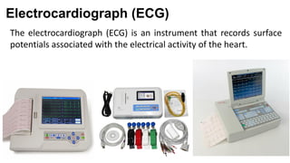
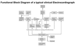
The Electrocardiograph
(ECG) Machine
Lecture Slide #2
BME 301: Principles of Diagnostic and Therapeutic Equipment
Electrocardiograph (ECG)
The electrocardiograph (ECG) is an instrument that records surface
potentials associated with the electrical activity of the heart.
Electrocardiograph (ECG)
The electrocardiograph (ECG) is an instrument that records surface
potentials associated with the electrical activity of the heart.
Electrocardiograph (ECG)
Functional Block Diagram of a typical clinical Electrocardiograph
Functional Blocks of a typical clinical Electrocardiograph Machine
• Protection circuit
• Lead selector
• Calibration signal
• Preamplifier
• Isolation circuit
• Driven right leg circuit
• Driver amplifier
• Memory system
• Microcomputer
• Recorder / printer
Protection Circuit
Includes protection devices so that high voltages that may appear across the
input to the ECG machine under certain conditions do not damage it.
Lead selector
Each electrode connected to the subject is attached to the lead selector of the
ECG machine.
• Determines which electrodes are necessary for a particular lead and
connects them to the remainder of the circuit.
• The connections for the central terminal are made here.
• This block can be controlled by the operator or by microcomputer of the
electrocardiograph in automatic mode.
• It selects one or more leads to be recorded
• In automatic mode, each of the 12 lead is recorded for short duration
(10s)
Calibration Signal
A 1mV calibration signal is momentarily introduced into the electrocardiograph
for each channel that is recorded.
Pre-amplifier
• The input preamplifier stage carries out the initial amplification of the ECG.
• This stage should have a very high input impedance and a high CMRR.
• A typical preamplifier stage can be a differential amplifier that consists of
three Op-amps as shown in the figure.
• A gain control switch is generally included as a part of this stage.
Isolation circuit
Contains a barrier to the passage of current from the power line (50 or 60 Hz).
For instance, if the patient came in contact with a 120V line, this barrier will prevent the
dangerous currents from flowing from the patient through the amplifier to the ground of the
recorder / microcomputer.
The isolation circuits are primarily for the protection of the patient in that they eliminate the
hazard of electric shock resulting from interacting among the patient, the electrocardiograph
and other electric devices in the patient’s environment.
Driven right leg circuit
• Used to minimize the common mode interference.
• This circuit provides a reference point on the patient that normally is at
ground potential.
• This connection is made to an electrode on the patients’ right leg.
Driven right leg circuit
Driver amplifier
• This amplifies the ECG to a level at which it can appropriately record the signal on
the recorder.
• This stage also carries out the Band Pass filtering of the electrocardiograph to give
the frequency characteristics as desired.
• Its input should be AC-coupled so that the offset voltages amplified by the
preamplifier are not seen at its input. These DC voltages, when amplified by this stage,
may cause it to saturate.
• Also, it often has a zero-offset control that is used to position the signal on the chart
paper. This control adjusts the DC level of the output signal.
Memory system
• Modern ECG machines store the graphs in memory as well as display on the paper
chart.
The signal is first digitized by an ADC and then, the samples from each lead are stored in
the memory.
• Patient information entered via keyboard is also stored. The microcomputer controls
this activity.
Microcomputer
• This controls the overall operation of the machine
• In certain machines, preliminary analysis of ECG also can be done to
determine many cardiovascular factors like heart rate, intervals, some
types of arrhythmias.
• A keyboard and a display unit help the operator to communicate with the
microcomputer.
• The operator can select several modes of operation by
invoking the respective programs.
Recorder / Printer
• This provides a hard copy of the recorded ECG signal
• This also prints the patient data and other clinical information entered by
the operator and the results of automatic analysis of the ECG.
• Digitized ECGs can also be stored in Flash Drives or DVDs.
Problems Frequently Encountered
There are many factors that must be taken into consideration in the design and
applications of Electrocardiograph as well as other Biopotential amplifiers. Those
are-
 Frequency Distortion
 Saturation or Cut-Off Distortion
 Ground Loops
 Open Lead Wires
 Artifact from Large Electric Transients
 Interference from Electric Devices
 Other sources of Electric Interference
Frequency Distortion
• The ECG machine does not always meet the frequency response standards.
• High Frequency distortion rounds of the sharp corners of the waveforms and
diminishes the amplitude of QRS complex.
• An instrument that have a frequency response of 1 to 150 Hz shows low
frequency distortion.
• Effect: Baseline does not remain horizontal. Monophasic waves in ECG
appears to be more Biphasic.
Saturation or Cut-Off Distortion
Ground Loops
Artifact from Large Electric Transients
Interference from Electric Devices
How to minimize?
Interference from Electric Devices
How to minimize?
Other Sources of Electric Interference
How to minimize?
Source
Webster, Chapter 6, Page. 250-263
Thank You

Ecg machine

  • 1.
    The Electrocardiograph (ECG) Machine LectureSlide #2 BME 301: Principles of Diagnostic and Therapeutic Equipment
  • 2.
    Electrocardiograph (ECG) The electrocardiograph(ECG) is an instrument that records surface potentials associated with the electrical activity of the heart.
  • 3.
    Electrocardiograph (ECG) The electrocardiograph(ECG) is an instrument that records surface potentials associated with the electrical activity of the heart.
  • 4.
  • 5.
    Functional Block Diagramof a typical clinical Electrocardiograph
  • 6.
    Functional Blocks ofa typical clinical Electrocardiograph Machine • Protection circuit • Lead selector • Calibration signal • Preamplifier • Isolation circuit • Driven right leg circuit • Driver amplifier • Memory system • Microcomputer • Recorder / printer
  • 7.
    Protection Circuit Includes protectiondevices so that high voltages that may appear across the input to the ECG machine under certain conditions do not damage it.
  • 8.
    Lead selector Each electrodeconnected to the subject is attached to the lead selector of the ECG machine. • Determines which electrodes are necessary for a particular lead and connects them to the remainder of the circuit. • The connections for the central terminal are made here. • This block can be controlled by the operator or by microcomputer of the electrocardiograph in automatic mode. • It selects one or more leads to be recorded • In automatic mode, each of the 12 lead is recorded for short duration (10s)
  • 9.
    Calibration Signal A 1mVcalibration signal is momentarily introduced into the electrocardiograph for each channel that is recorded.
  • 10.
    Pre-amplifier • The inputpreamplifier stage carries out the initial amplification of the ECG. • This stage should have a very high input impedance and a high CMRR. • A typical preamplifier stage can be a differential amplifier that consists of three Op-amps as shown in the figure. • A gain control switch is generally included as a part of this stage.
  • 11.
    Isolation circuit Contains abarrier to the passage of current from the power line (50 or 60 Hz). For instance, if the patient came in contact with a 120V line, this barrier will prevent the dangerous currents from flowing from the patient through the amplifier to the ground of the recorder / microcomputer. The isolation circuits are primarily for the protection of the patient in that they eliminate the hazard of electric shock resulting from interacting among the patient, the electrocardiograph and other electric devices in the patient’s environment.
  • 12.
    Driven right legcircuit • Used to minimize the common mode interference. • This circuit provides a reference point on the patient that normally is at ground potential. • This connection is made to an electrode on the patients’ right leg.
  • 13.
  • 14.
    Driver amplifier • Thisamplifies the ECG to a level at which it can appropriately record the signal on the recorder. • This stage also carries out the Band Pass filtering of the electrocardiograph to give the frequency characteristics as desired. • Its input should be AC-coupled so that the offset voltages amplified by the preamplifier are not seen at its input. These DC voltages, when amplified by this stage, may cause it to saturate. • Also, it often has a zero-offset control that is used to position the signal on the chart paper. This control adjusts the DC level of the output signal.
  • 15.
    Memory system • ModernECG machines store the graphs in memory as well as display on the paper chart. The signal is first digitized by an ADC and then, the samples from each lead are stored in the memory. • Patient information entered via keyboard is also stored. The microcomputer controls this activity.
  • 16.
    Microcomputer • This controlsthe overall operation of the machine • In certain machines, preliminary analysis of ECG also can be done to determine many cardiovascular factors like heart rate, intervals, some types of arrhythmias. • A keyboard and a display unit help the operator to communicate with the microcomputer. • The operator can select several modes of operation by invoking the respective programs.
  • 17.
    Recorder / Printer •This provides a hard copy of the recorded ECG signal • This also prints the patient data and other clinical information entered by the operator and the results of automatic analysis of the ECG. • Digitized ECGs can also be stored in Flash Drives or DVDs.
  • 18.
    Problems Frequently Encountered Thereare many factors that must be taken into consideration in the design and applications of Electrocardiograph as well as other Biopotential amplifiers. Those are-  Frequency Distortion  Saturation or Cut-Off Distortion  Ground Loops  Open Lead Wires  Artifact from Large Electric Transients  Interference from Electric Devices  Other sources of Electric Interference
  • 19.
    Frequency Distortion • TheECG machine does not always meet the frequency response standards. • High Frequency distortion rounds of the sharp corners of the waveforms and diminishes the amplitude of QRS complex. • An instrument that have a frequency response of 1 to 150 Hz shows low frequency distortion. • Effect: Baseline does not remain horizontal. Monophasic waves in ECG appears to be more Biphasic.
  • 20.
  • 21.
  • 22.
    Artifact from LargeElectric Transients
  • 23.
    Artifact from LargeElectric Transients
  • 24.
  • 25.
  • 26.
    Interference from ElectricDevices How to minimize?
  • 27.
    Interference from ElectricDevices How to minimize?
  • 28.
    Other Sources ofElectric Interference How to minimize?
  • 29.
  • 30.