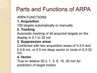
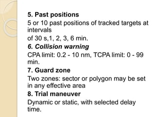
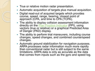
ARPA
(Automatic Radar Plotting Aids)
 ARPA is an acronym for Automatic Radar Plotting
Aid. It is a sophisticated piece of navigation
equipment found on the bridge of most ocean-
going vessels that combines a traditional radar
display with a computer driven plotting device.
After either manual or automatic acquisition of
radar targets the ARPA will compute and display
a variety of information useful to the navigator in
making collision avoidance and navigational
decisions. It is indispensable when navigating in
areas of high traffic density such as the Straits of
Mollucca or the English Channel, especially in
restricted visibility.
 A marine radar with automatic radar plotting
aid (ARPA) capability can create tracks using
radar contacts. The system can calculate the
tracked object's course, speed and closest point
of approach (CPA), thereby knowing if there is a
danger of collision with the other ship or
landmass.
Characteristics of ARPA
ARPA RADAR FUNCTIONALITY
Basically ARPA radar is the equipment by means
of a computer system operating in conjunction with
radar. Radar transmitter generates very short pulses of
radio waves. When the waves of one of these pulses
encounter any obstacle, such as a ship or shore line, part
of the radiated energy is reflected and received by the
original radar. The reflected pulse constitutes a radio
echo. The time between radiating the pulse and receiving
the echo can be accurately measured. Therefore the
distance between the radar and the ship is calculated.
The direction of the ship is the direction of the pulse
transmitted
All radar installations should comply with IMO
minimum requirements. The variable range
marker
should enable the range of an object to be
measured with
an error not exceeding 1.5 per cent of the
maximum
range of the scale in use, or 70 meters,
whichever is the
greater. The means provided for bearings
should enable
the bearing of a target whose echo appears at
the edge of
the display to be measured with an accuracy of
plus or
minus 1 degree or better.
Parts and Functions of ARPA
ARPA FUNCTIONS
1. Acquisition
100 targets automatically or manually
2. Tracking
Automatic tracking of all acquired targets on the
display in 0.1 to 32 nm
3. Suppression areas
Combined with two acquisition areas of 3-3.5 and
5.5-6 nm, or 0.5 nm deep sector or circle in 0.3-32
nm.
4. Vector
True or relative 30 s, 1, 3, 6, 15, 30 min for
prediction of target motion
5. Past positions
5 or 10 past positions of tracked targets at
intervals
of 30 s,1, 2, 3, 6 min.
6. Collision warning
CPA limit: 0.2 - 10 nm, TCPA limit: 0 - 99
min.
7. Guard zone
Two zones: sector or polygon may be set
in any effective area
8. Trial maneuver
Dynamic or static, with selected delay
time.
 True or relative motion radar presentation.
 Automatic acquisition of targets plus manual acquisition.
 Digital read-out of acquired targets which provides
course, speed, range, bearing, closest point of
approach (CPA, and time to CPA (TCPA).
 The ability to display collision assessment information
directly on the Plan Position Indicator (PPI), using
vectors (true or relative) or a graphical Predicted Area
of Danger (PAD) display.
 The ability to perform trial maneuvers, including course
changes, speed changes, and combined course/speed
changes.
 Automatic ground stabilization for navigation purposes.
ARPA processes radar information much more rapidly
than conventional radar but is still subject to the same
limitations. ARPA data is only as accurate as the data
that comes from inputs such as the gyro and speed log.
Use of ARPA
 The use of ARPA will assist the
interpretation of radar data and could
reduce risk of collision and pollution of
marine environment.

Group 1 arpa

  • 1.
  • 2.
     ARPA isan acronym for Automatic Radar Plotting Aid. It is a sophisticated piece of navigation equipment found on the bridge of most ocean- going vessels that combines a traditional radar display with a computer driven plotting device. After either manual or automatic acquisition of radar targets the ARPA will compute and display a variety of information useful to the navigator in making collision avoidance and navigational decisions. It is indispensable when navigating in areas of high traffic density such as the Straits of Mollucca or the English Channel, especially in restricted visibility.  A marine radar with automatic radar plotting aid (ARPA) capability can create tracks using radar contacts. The system can calculate the tracked object's course, speed and closest point of approach (CPA), thereby knowing if there is a danger of collision with the other ship or landmass.
  • 3.
    Characteristics of ARPA ARPARADAR FUNCTIONALITY Basically ARPA radar is the equipment by means of a computer system operating in conjunction with radar. Radar transmitter generates very short pulses of radio waves. When the waves of one of these pulses encounter any obstacle, such as a ship or shore line, part of the radiated energy is reflected and received by the original radar. The reflected pulse constitutes a radio echo. The time between radiating the pulse and receiving the echo can be accurately measured. Therefore the distance between the radar and the ship is calculated. The direction of the ship is the direction of the pulse transmitted
  • 4.
    All radar installationsshould comply with IMO minimum requirements. The variable range marker should enable the range of an object to be measured with an error not exceeding 1.5 per cent of the maximum range of the scale in use, or 70 meters, whichever is the greater. The means provided for bearings should enable the bearing of a target whose echo appears at the edge of the display to be measured with an accuracy of plus or minus 1 degree or better.
  • 5.
    Parts and Functionsof ARPA ARPA FUNCTIONS 1. Acquisition 100 targets automatically or manually 2. Tracking Automatic tracking of all acquired targets on the display in 0.1 to 32 nm 3. Suppression areas Combined with two acquisition areas of 3-3.5 and 5.5-6 nm, or 0.5 nm deep sector or circle in 0.3-32 nm. 4. Vector True or relative 30 s, 1, 3, 6, 15, 30 min for prediction of target motion
  • 6.
    5. Past positions 5or 10 past positions of tracked targets at intervals of 30 s,1, 2, 3, 6 min. 6. Collision warning CPA limit: 0.2 - 10 nm, TCPA limit: 0 - 99 min. 7. Guard zone Two zones: sector or polygon may be set in any effective area 8. Trial maneuver Dynamic or static, with selected delay time.
  • 7.
     True orrelative motion radar presentation.  Automatic acquisition of targets plus manual acquisition.  Digital read-out of acquired targets which provides course, speed, range, bearing, closest point of approach (CPA, and time to CPA (TCPA).  The ability to display collision assessment information directly on the Plan Position Indicator (PPI), using vectors (true or relative) or a graphical Predicted Area of Danger (PAD) display.  The ability to perform trial maneuvers, including course changes, speed changes, and combined course/speed changes.  Automatic ground stabilization for navigation purposes. ARPA processes radar information much more rapidly than conventional radar but is still subject to the same limitations. ARPA data is only as accurate as the data that comes from inputs such as the gyro and speed log.
  • 8.
    Use of ARPA The use of ARPA will assist the interpretation of radar data and could reduce risk of collision and pollution of marine environment.