Download as PDF, PPTX
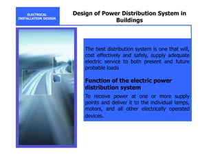
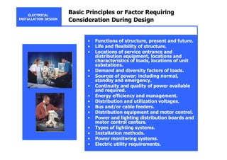
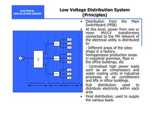
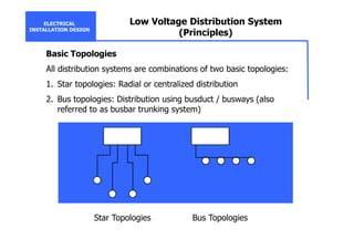
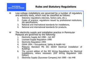
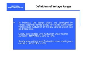
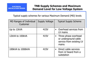
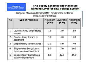
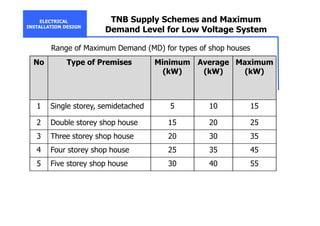
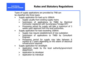
The document discusses the goals and principles of designing electrical installation and power distribution systems. It aims to 1) ensure safety, 2) minimize initial investment, and 3) maximize service continuity, flexibility, efficiency and power quality. The design considers factors like load locations and characteristics, sources of power, utility requirements and voltage levels. Low voltage distribution systems typically use star or bus topologies in a three-level scheme. Regulations in Malaysia govern aspects like supply voltage ranges and schemes based on maximum demand levels.