Downloaded 21 times


![Schneider Electric - Electrical installation guide 2016
B43
©SchneiderElectric-allrightsreserved
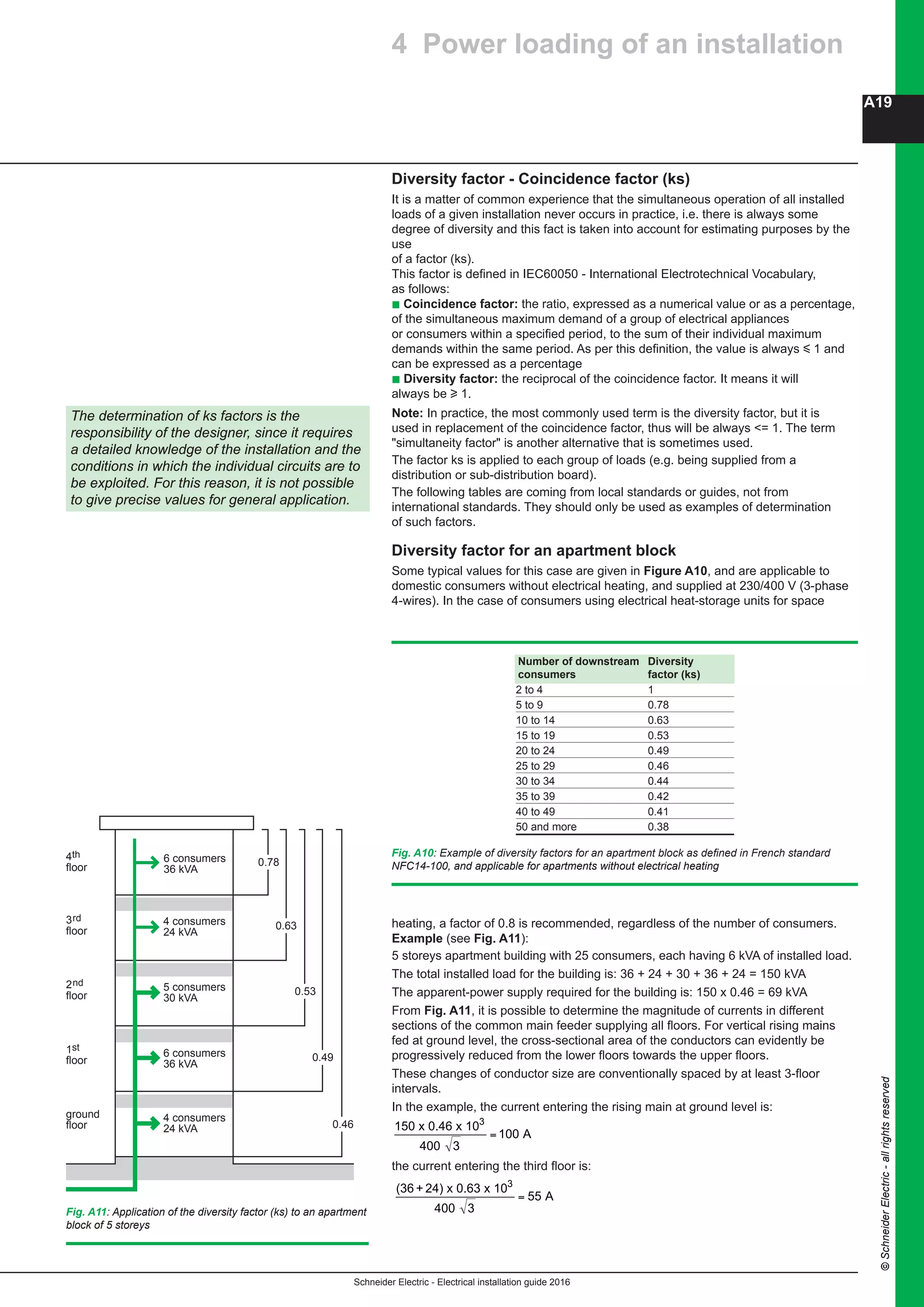
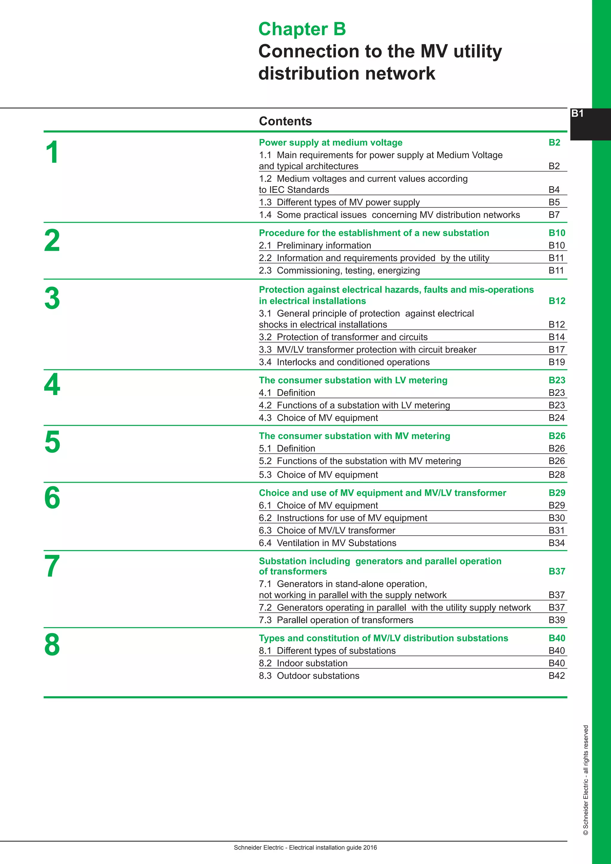
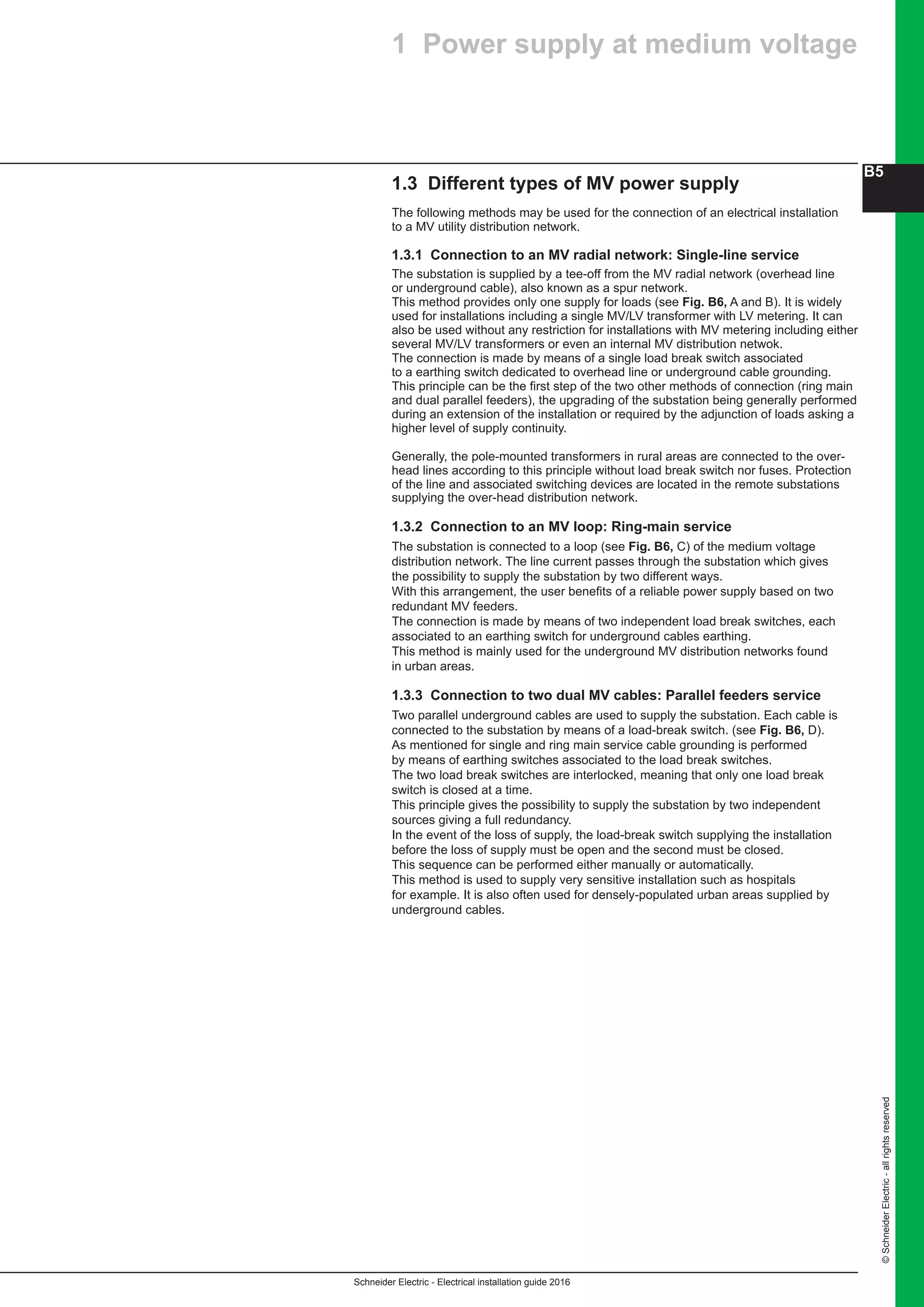
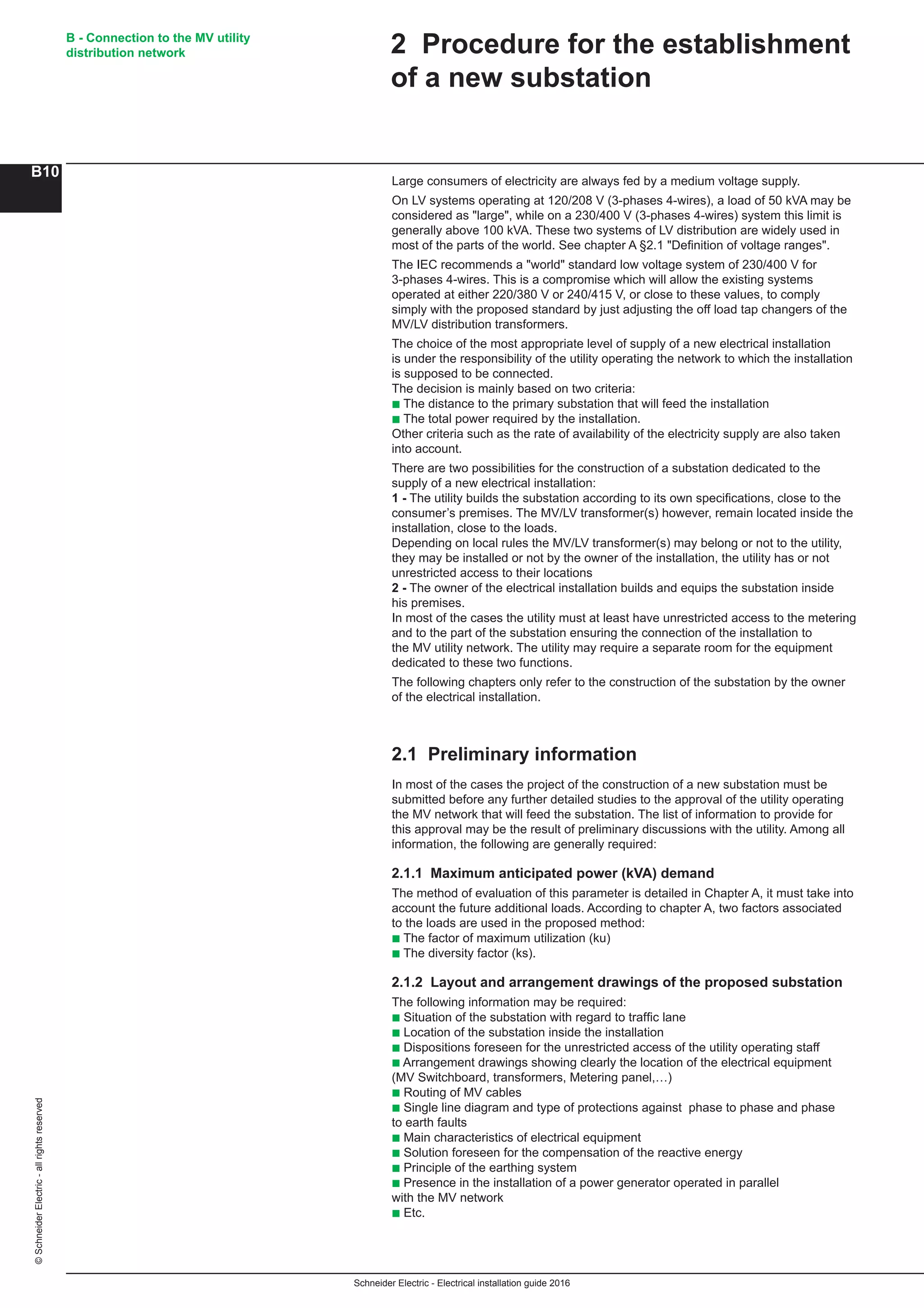
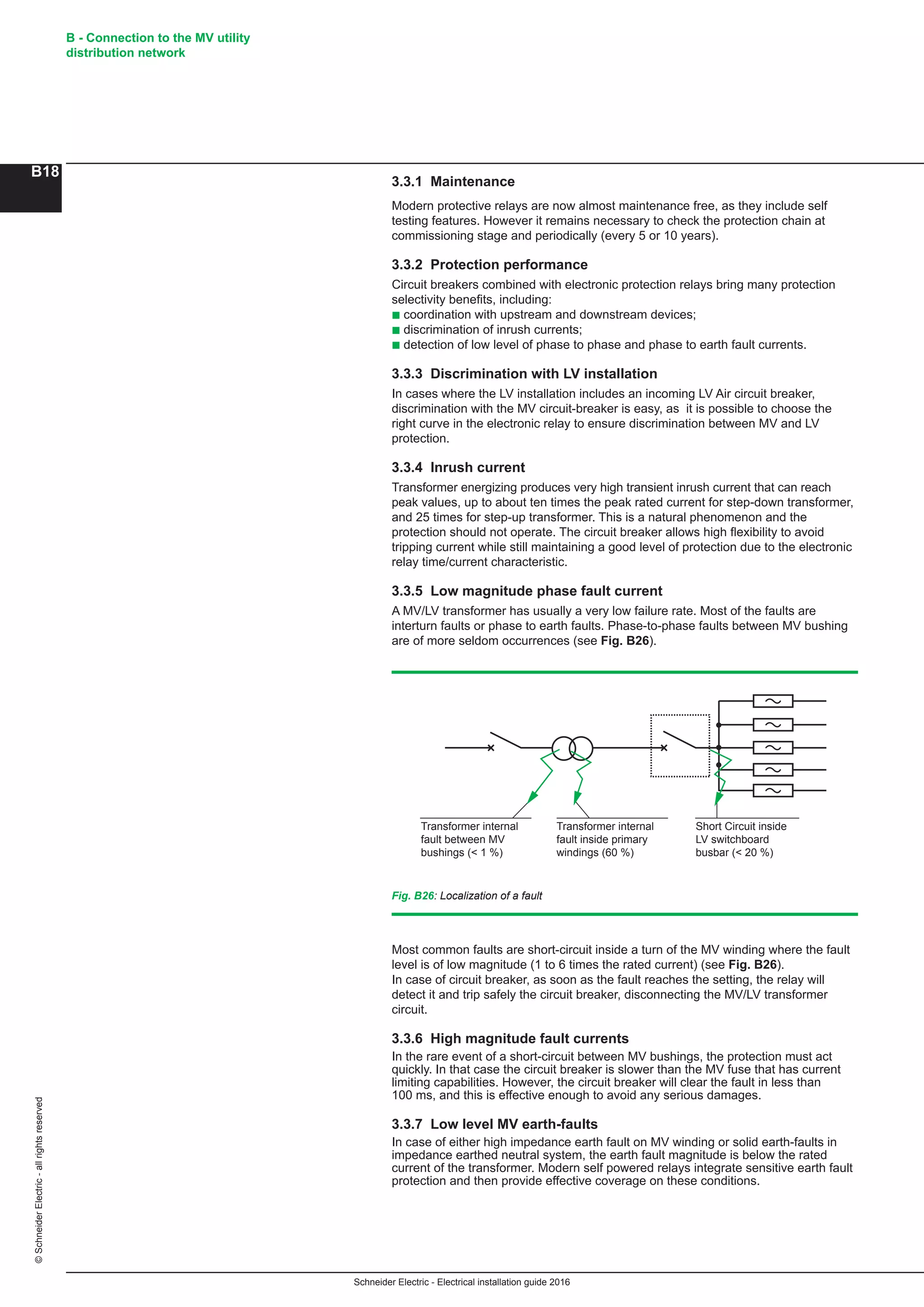
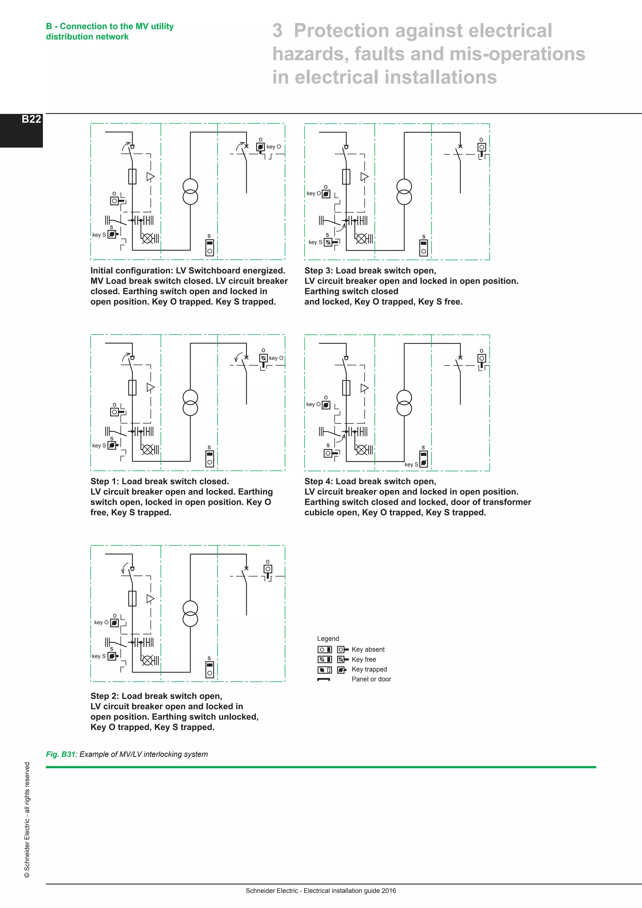
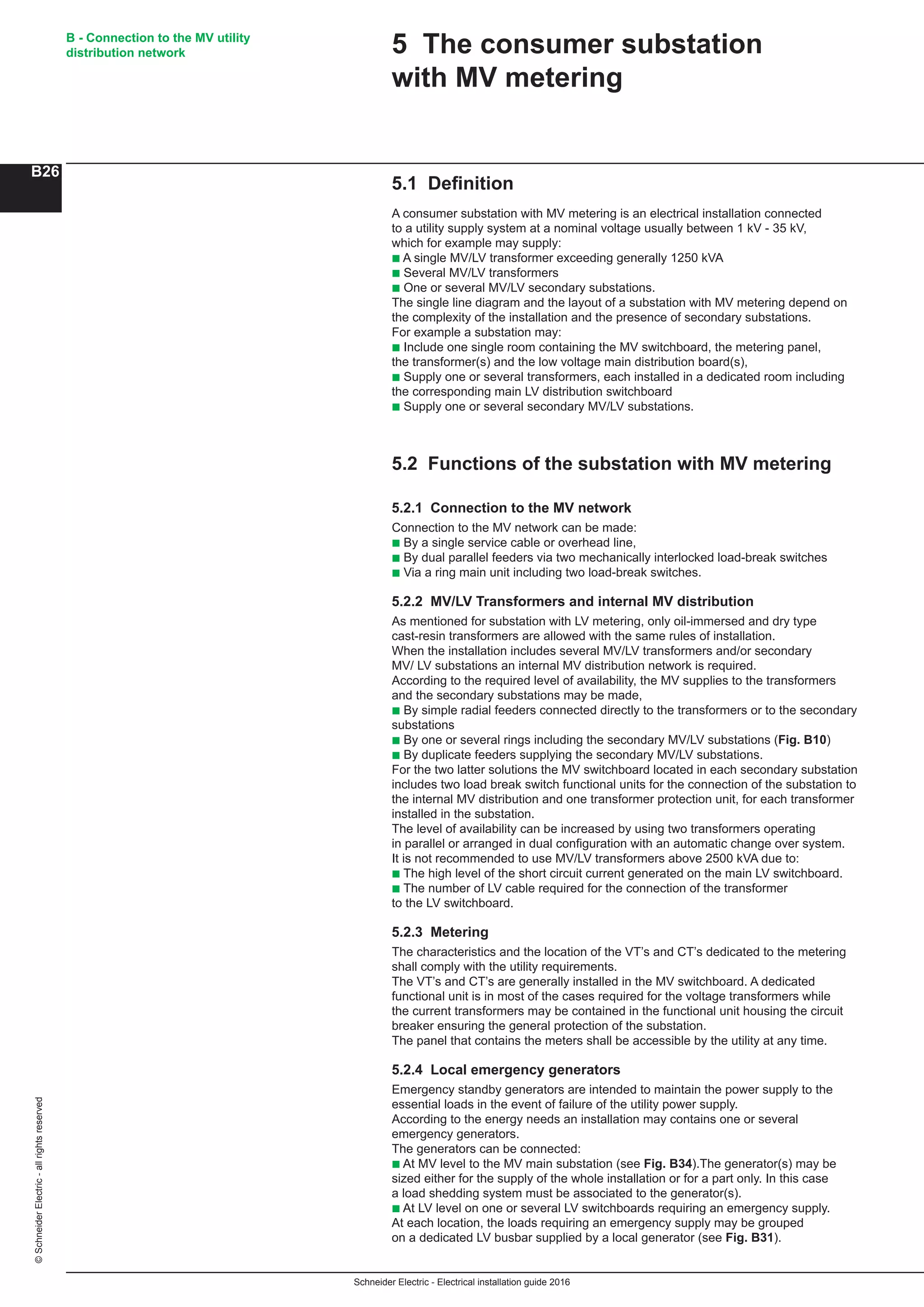
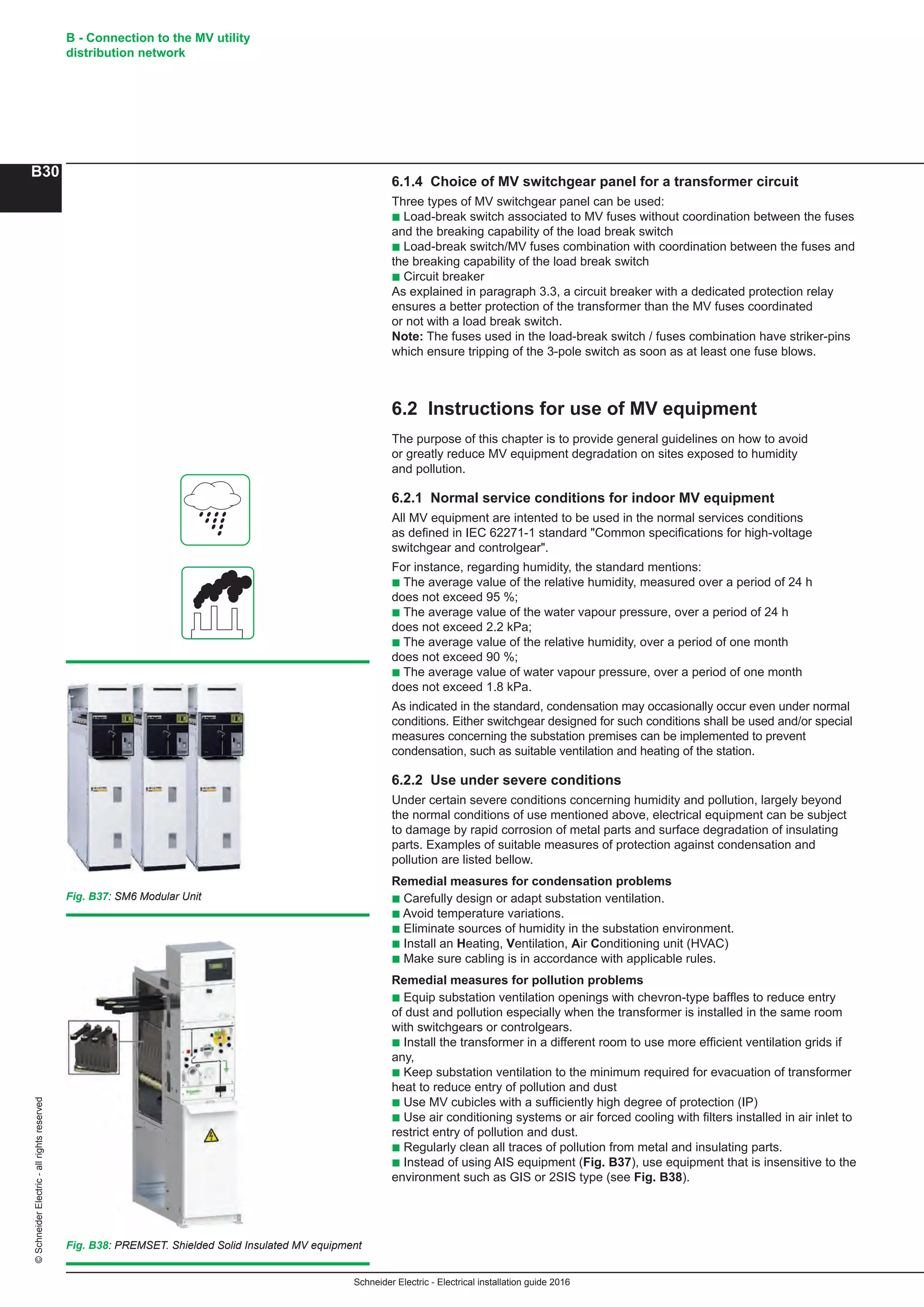
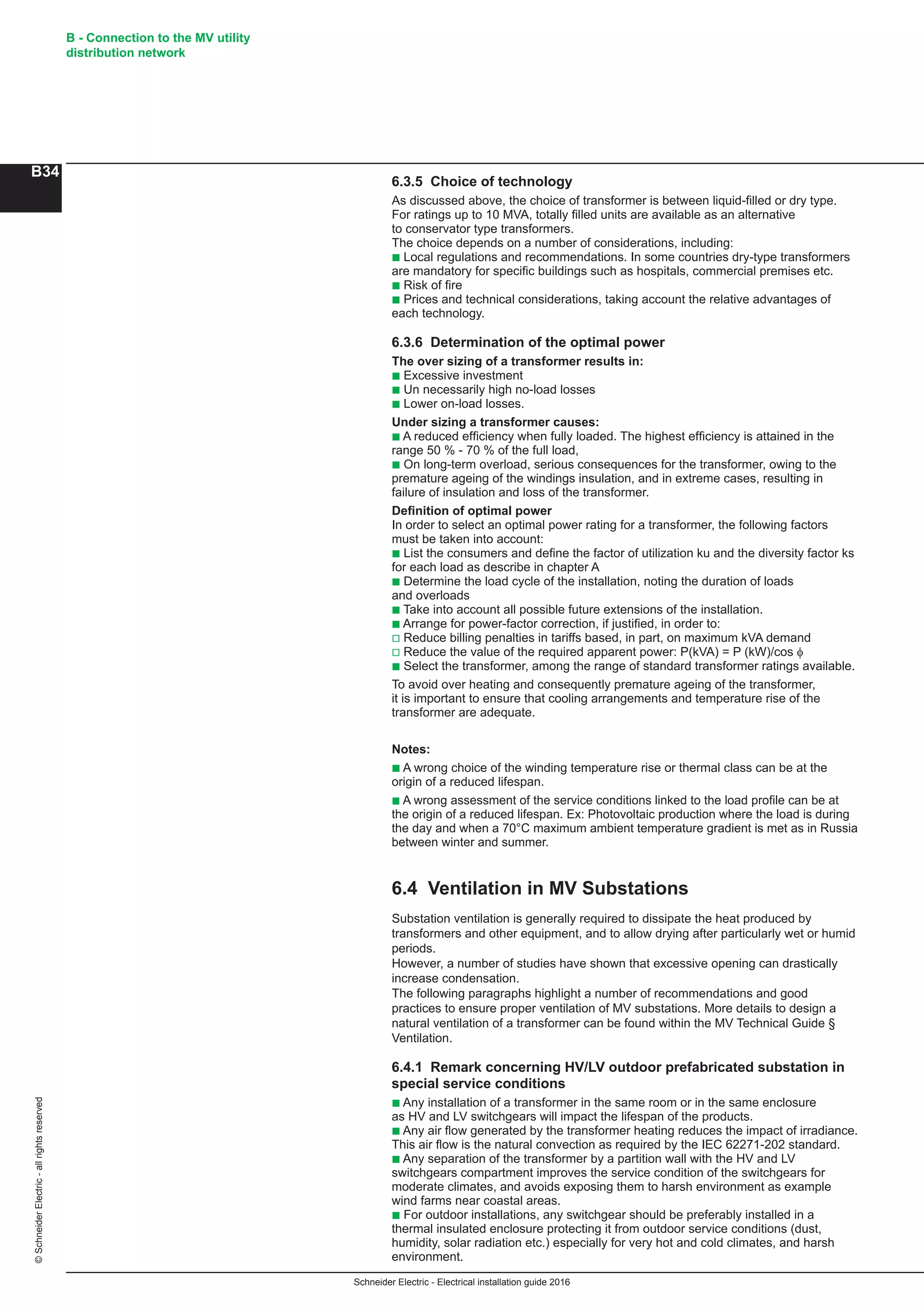
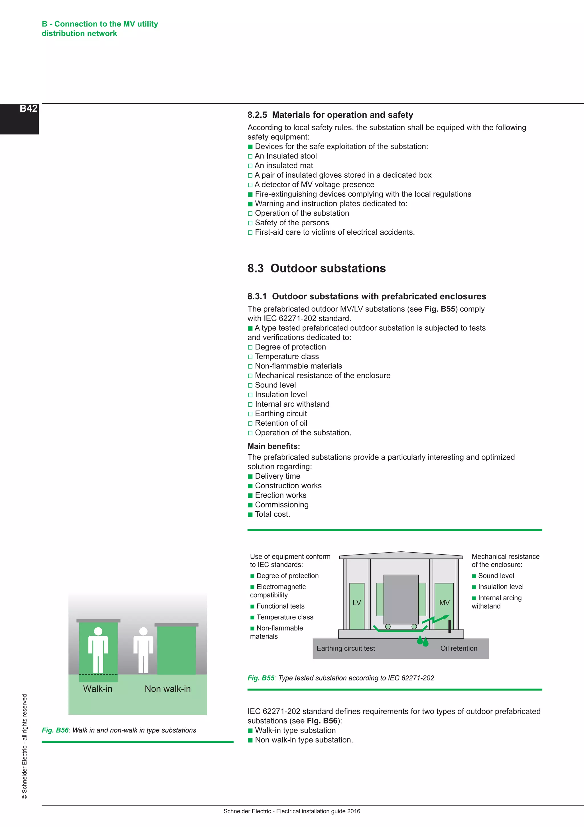
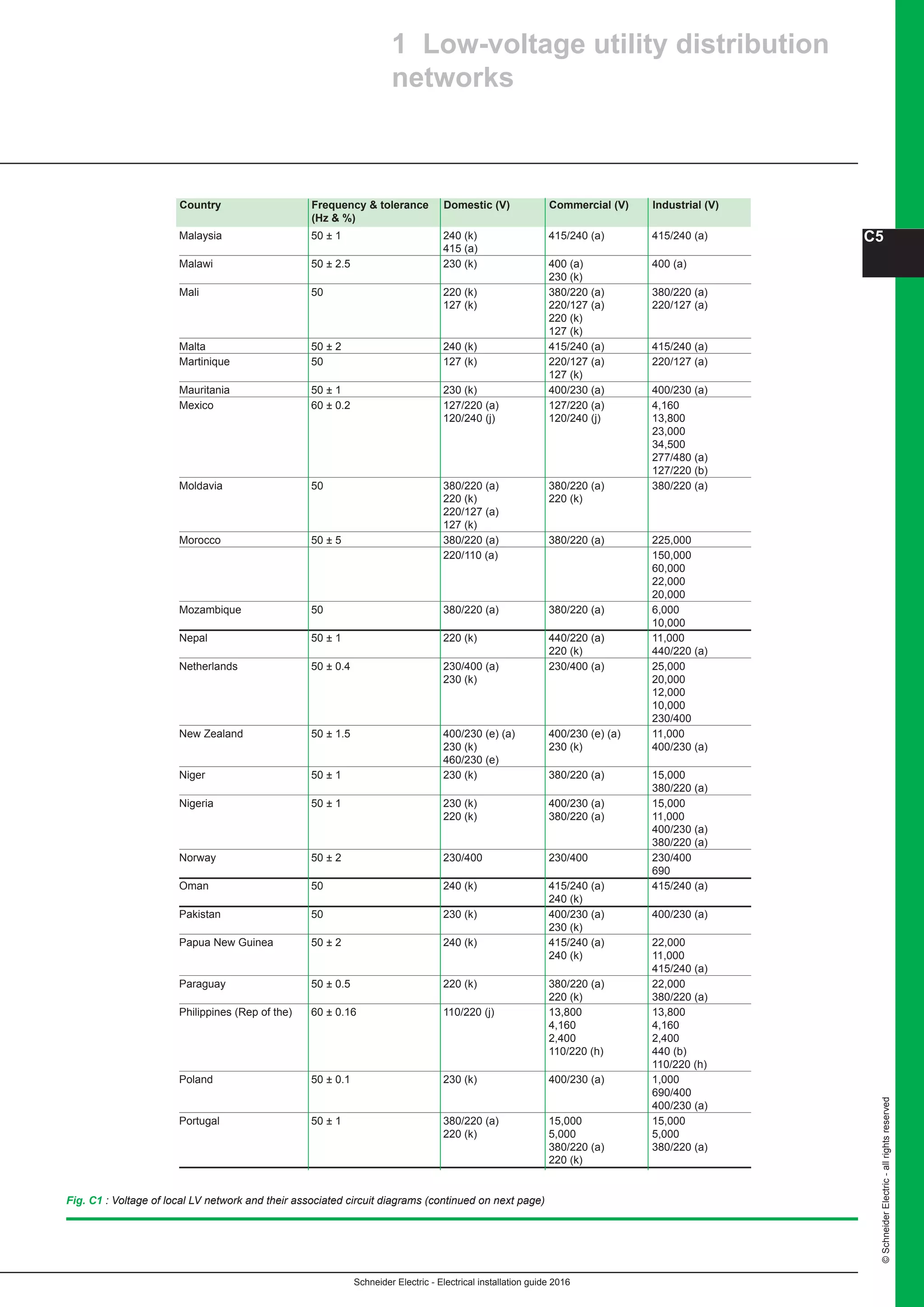
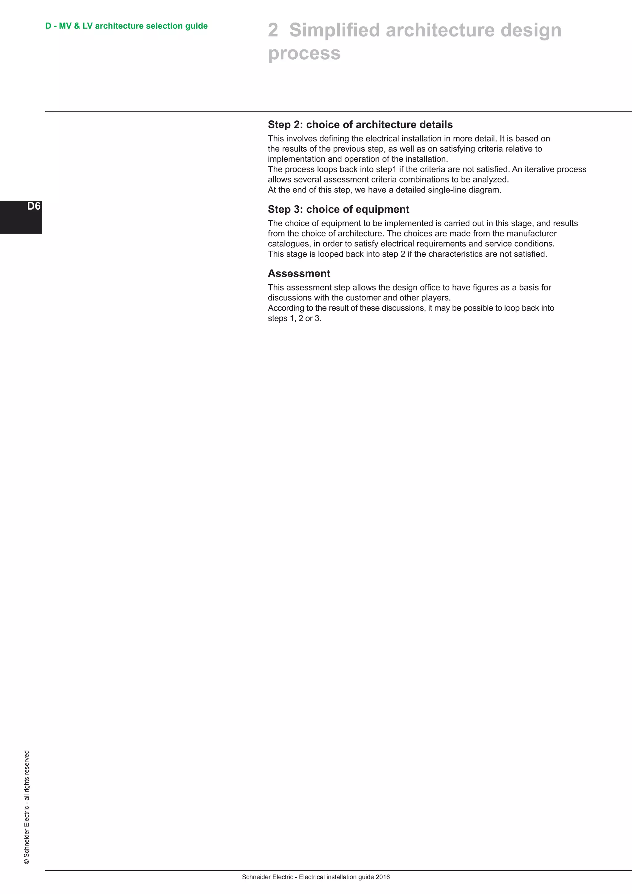
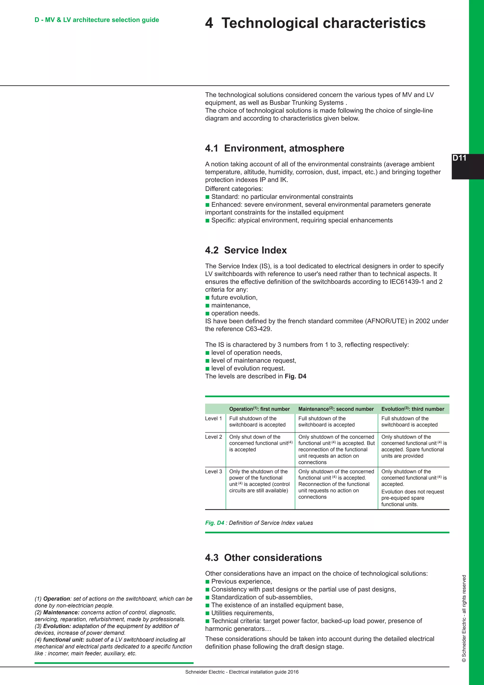
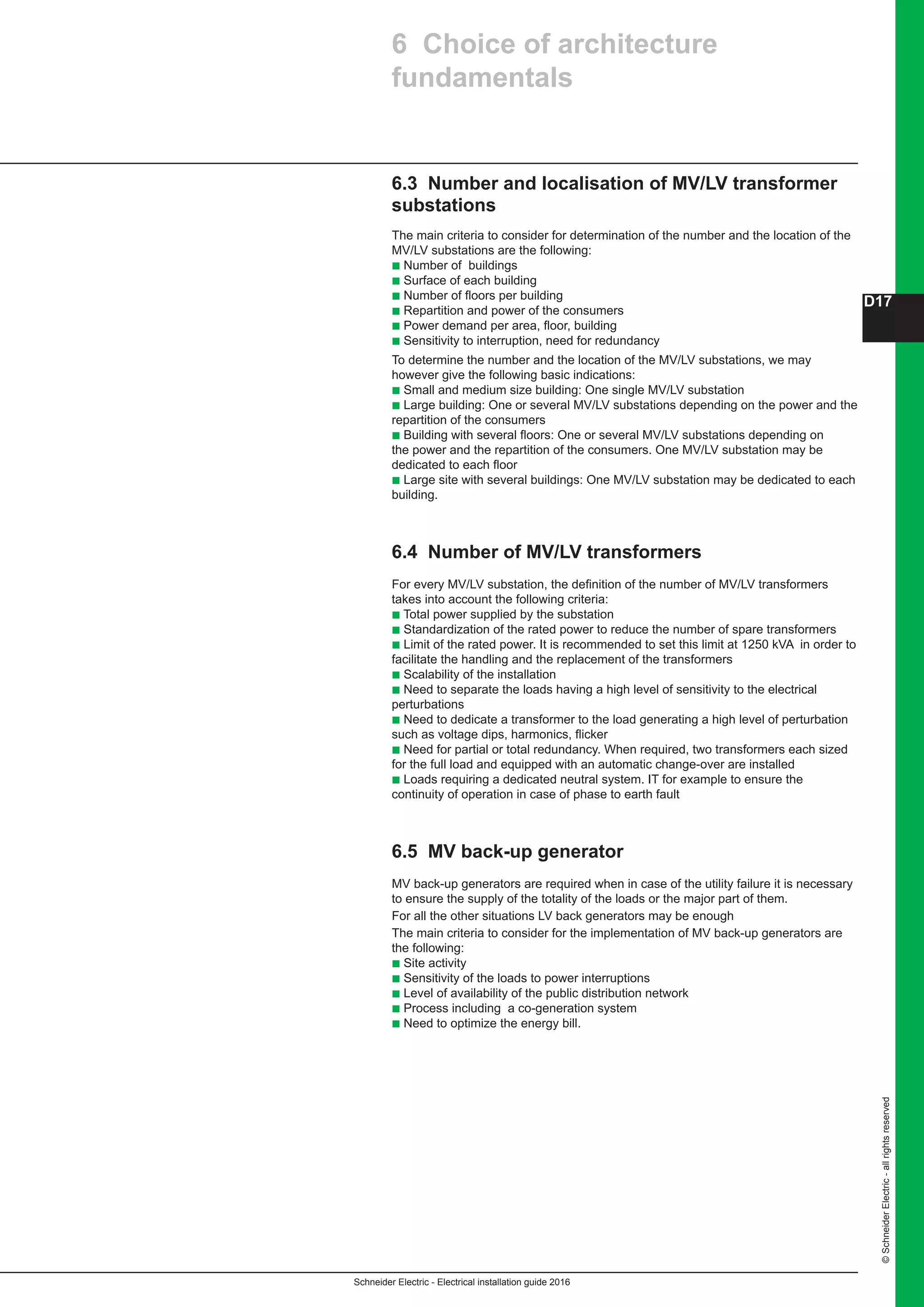
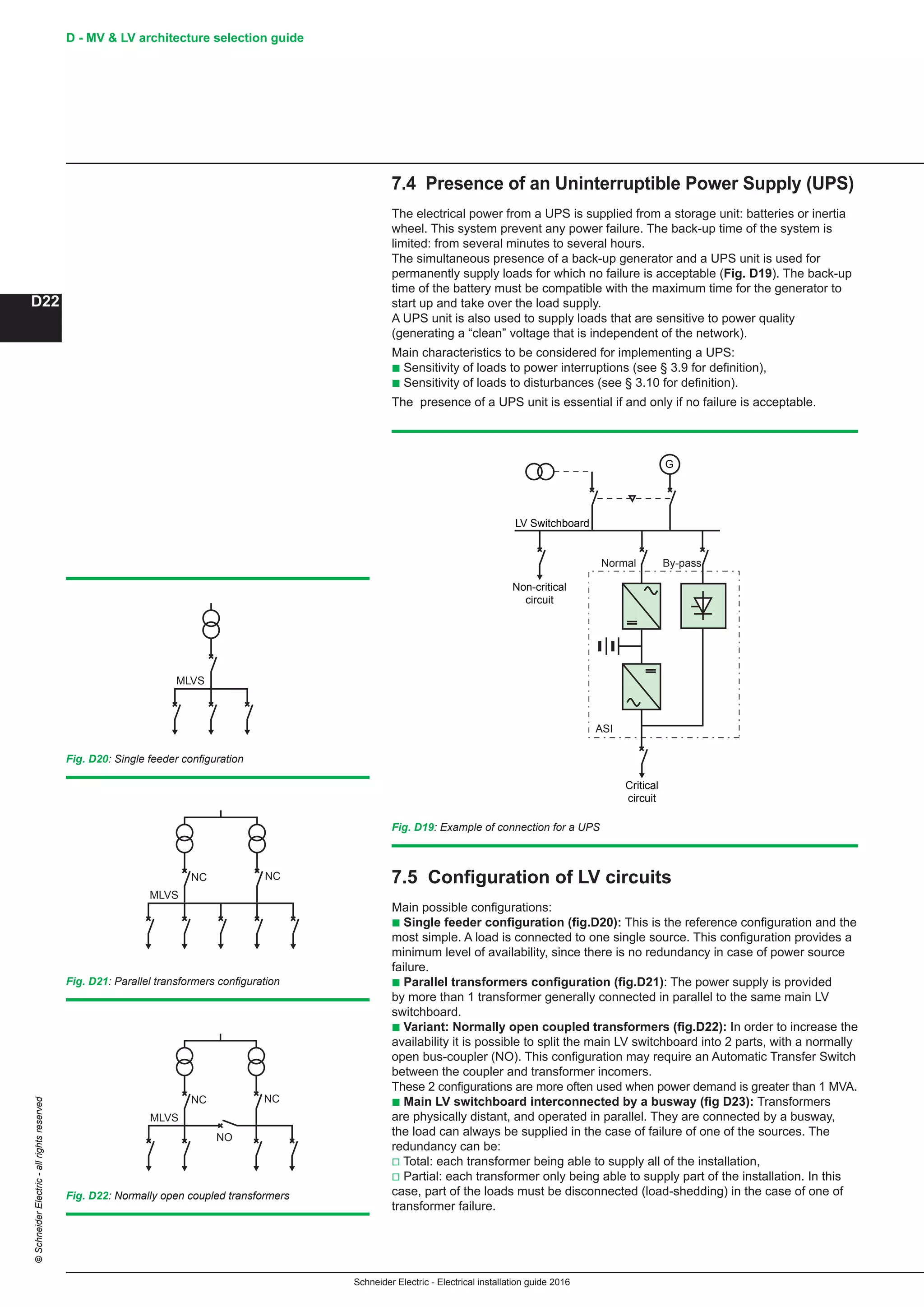
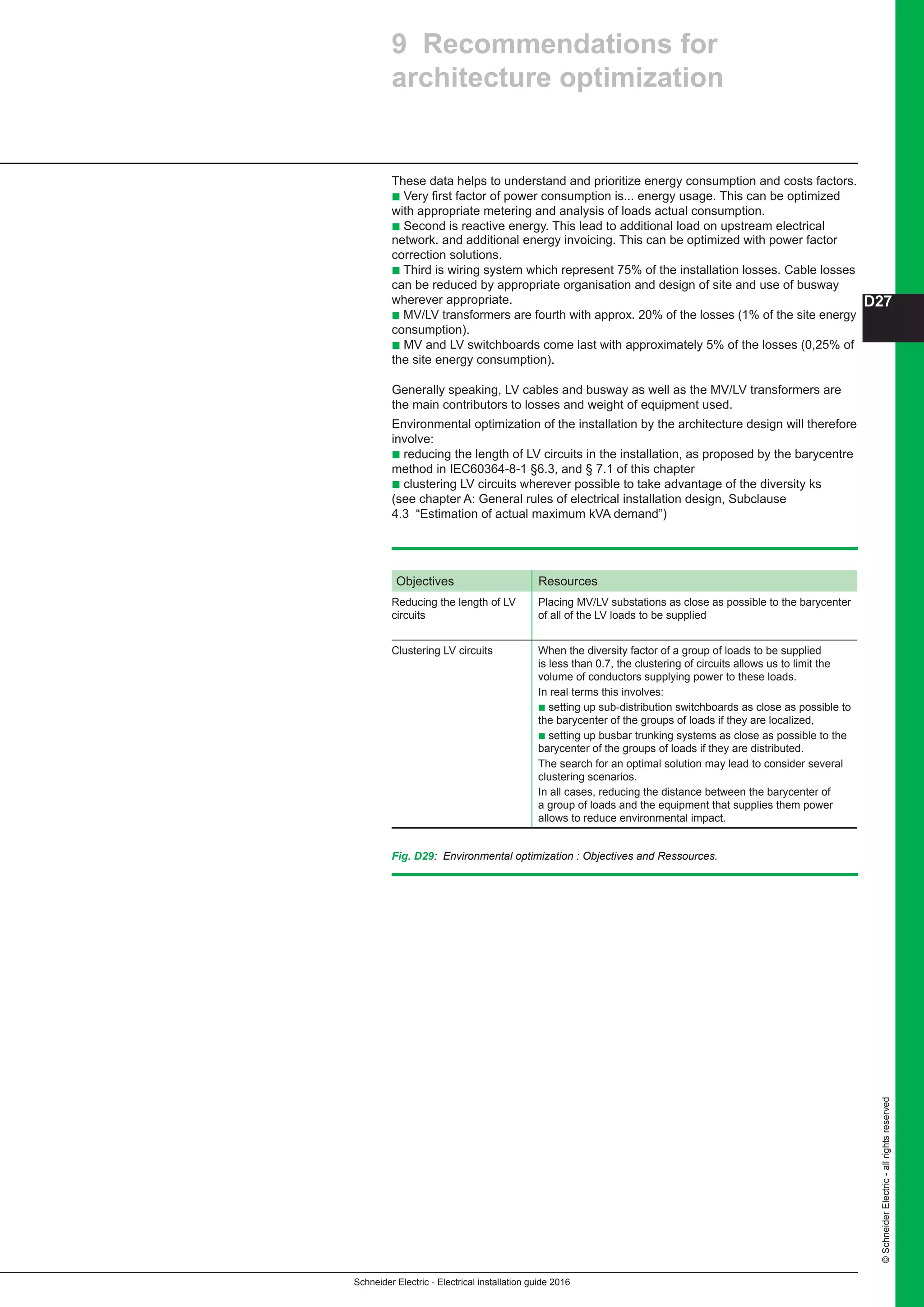
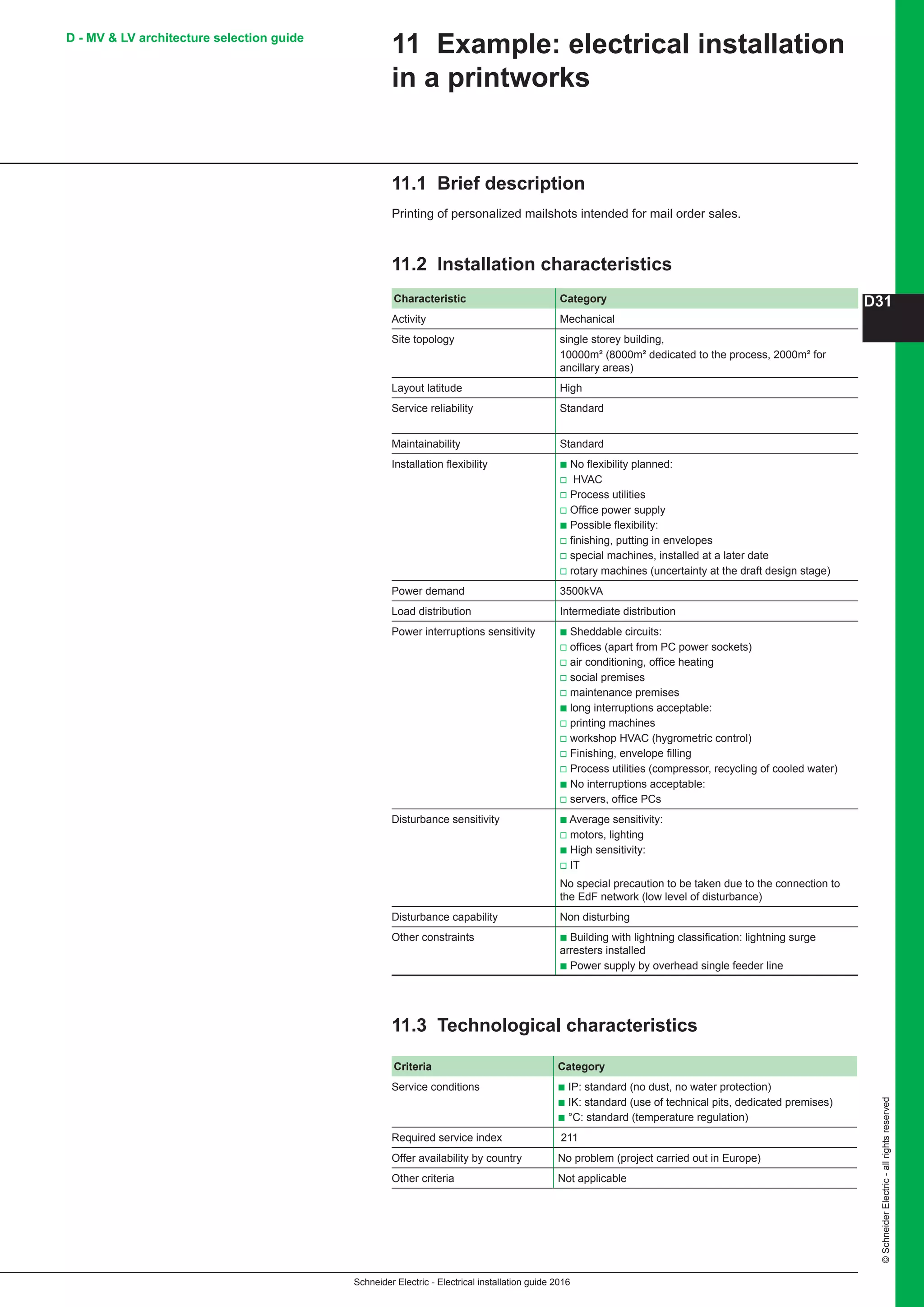
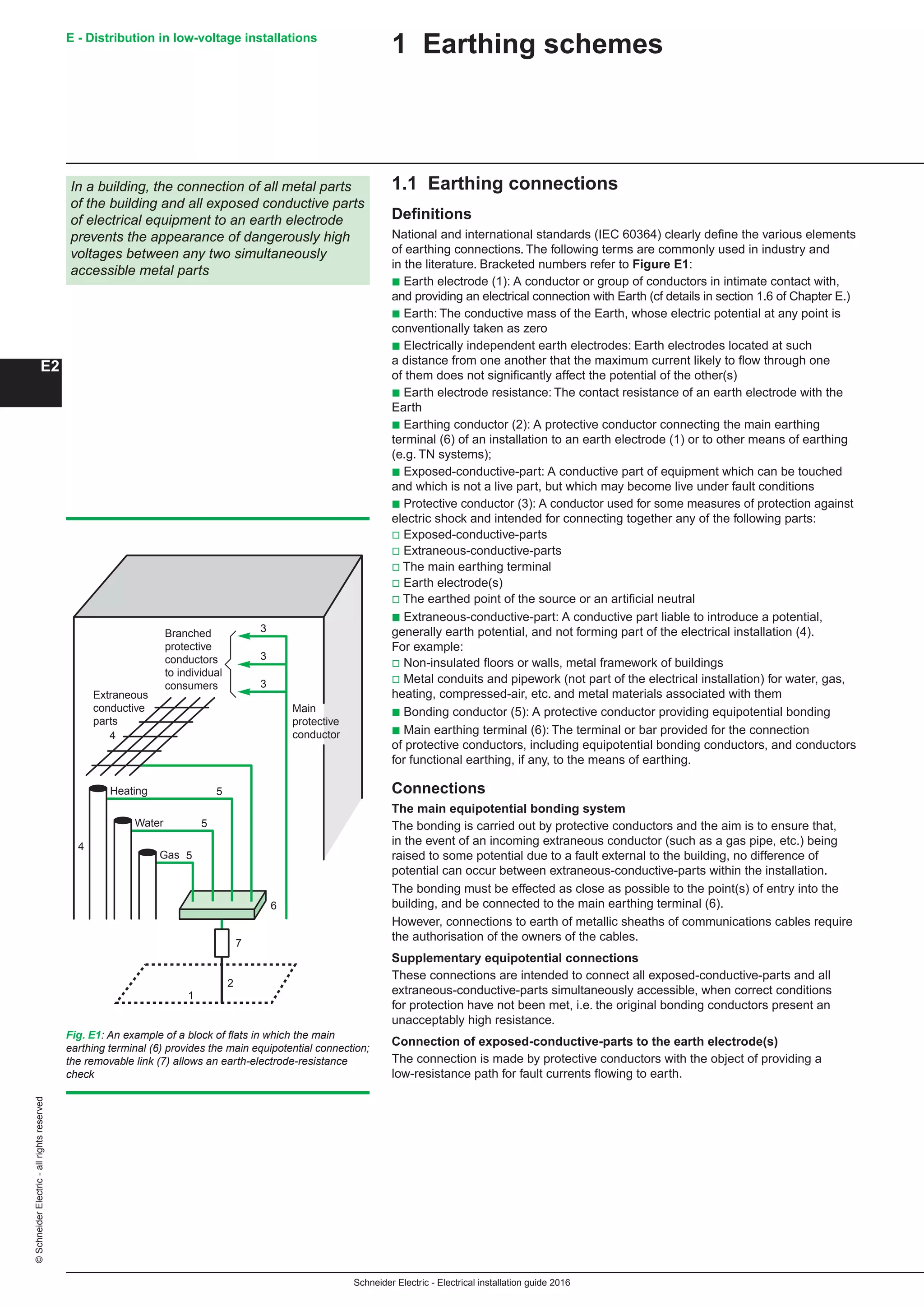
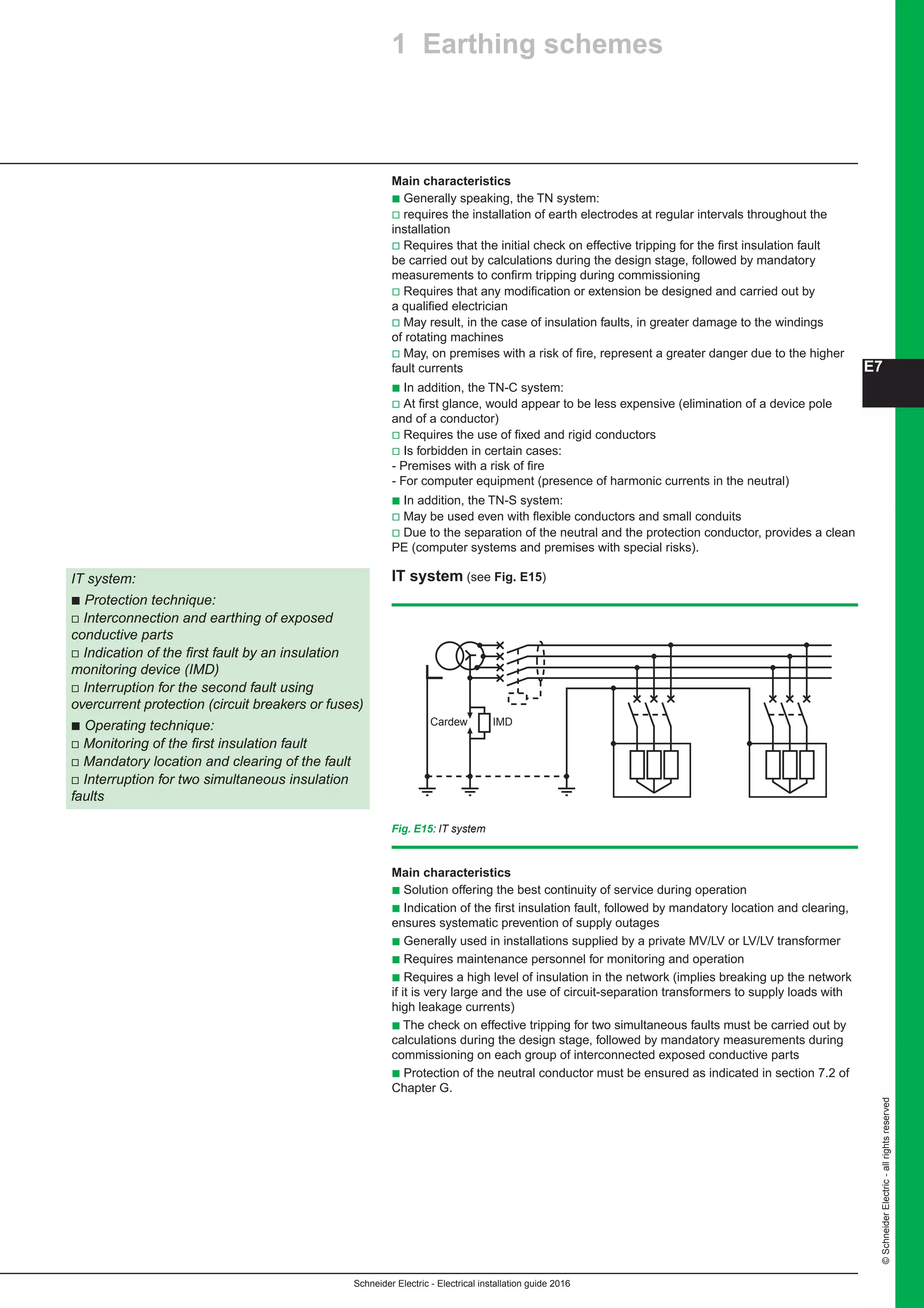
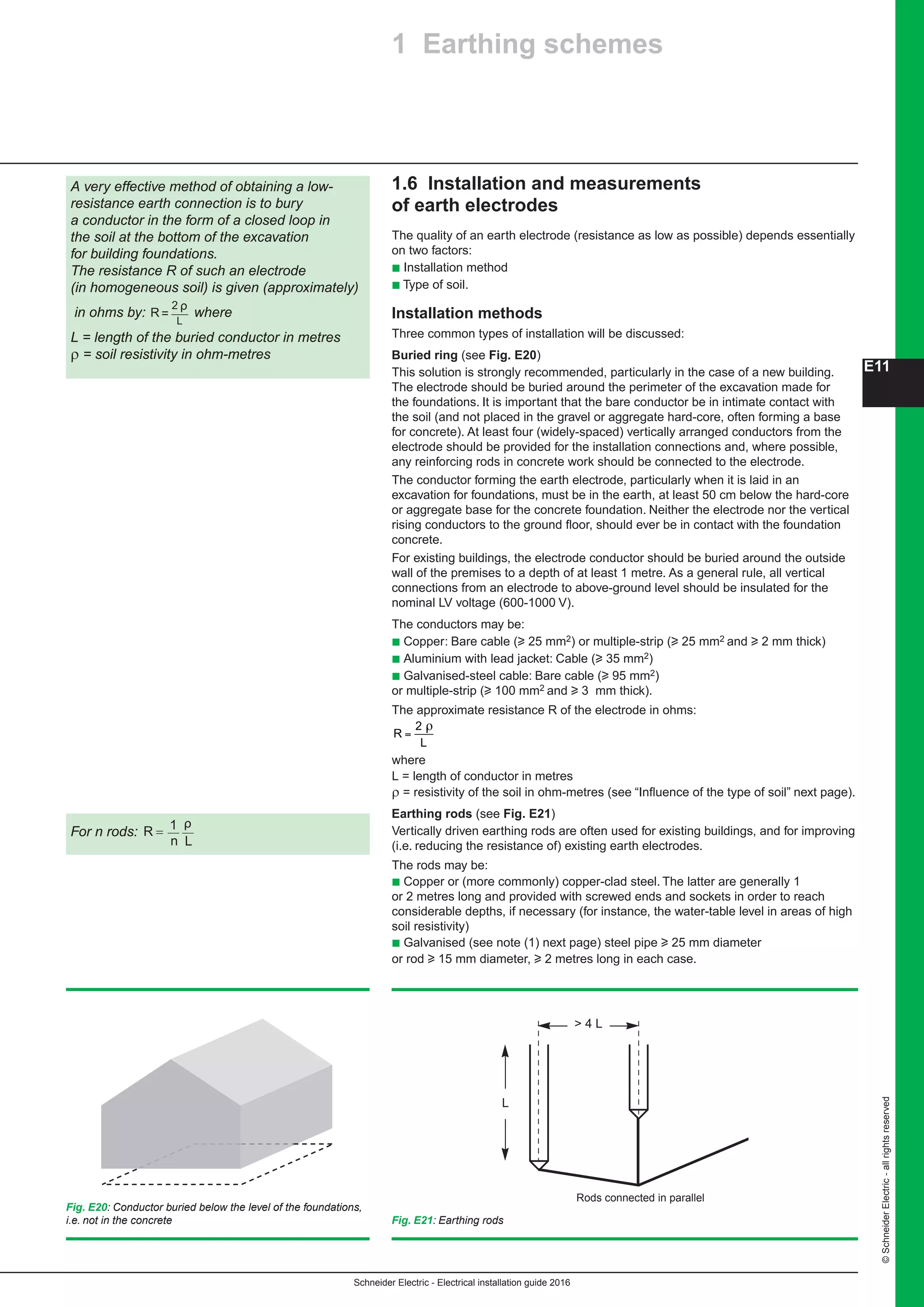
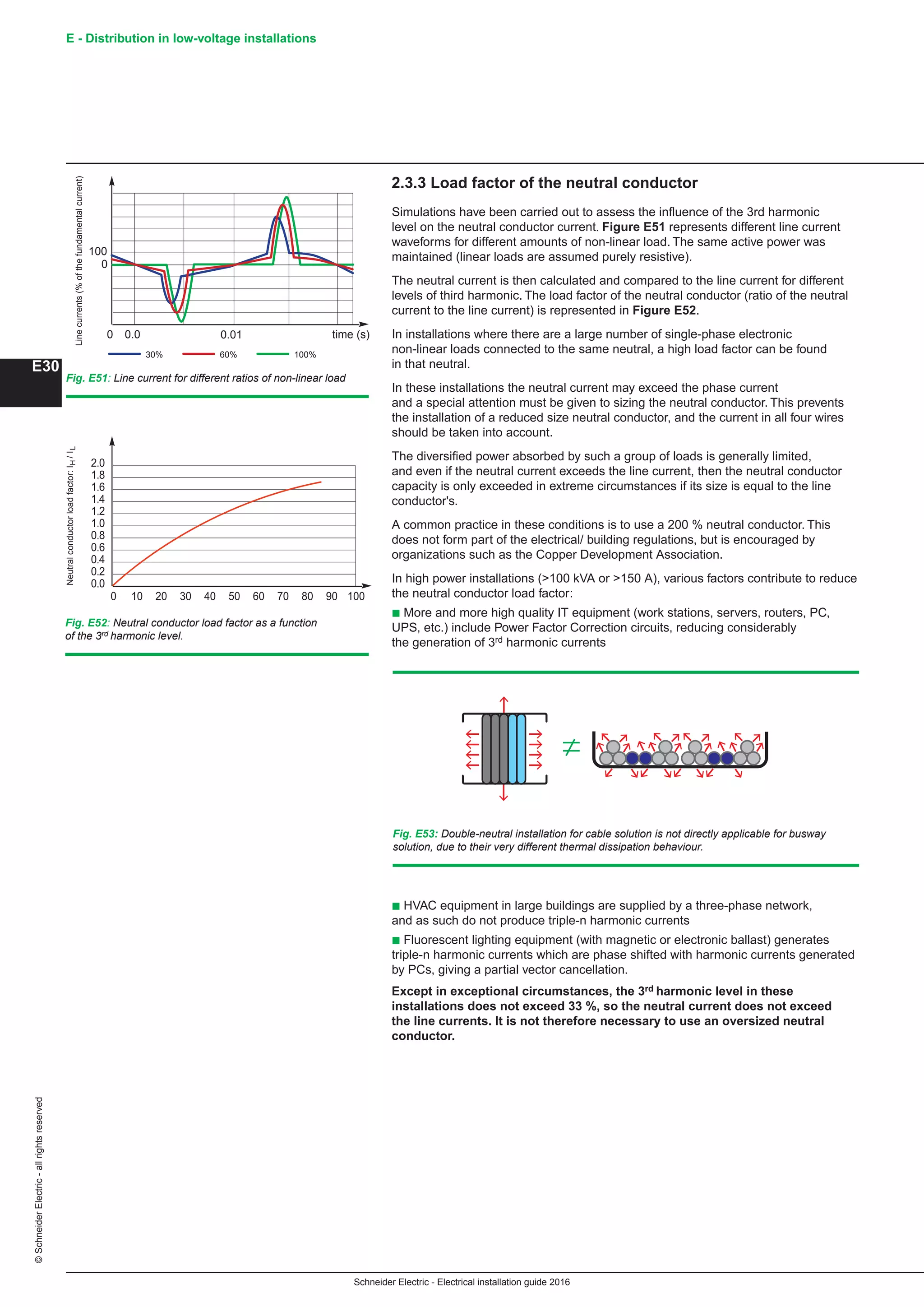
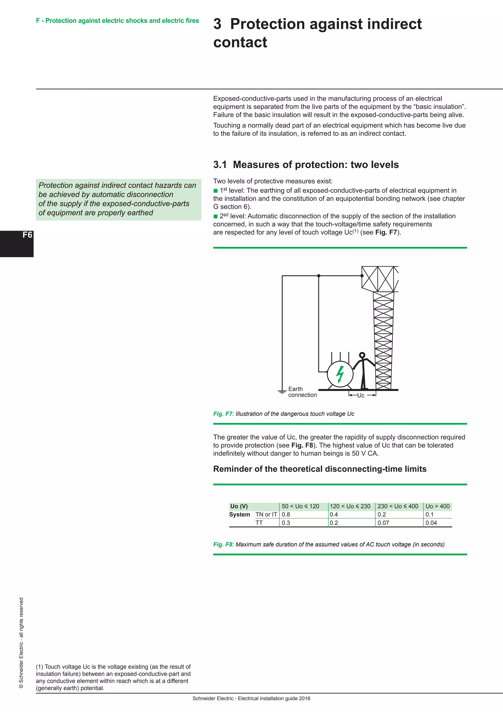
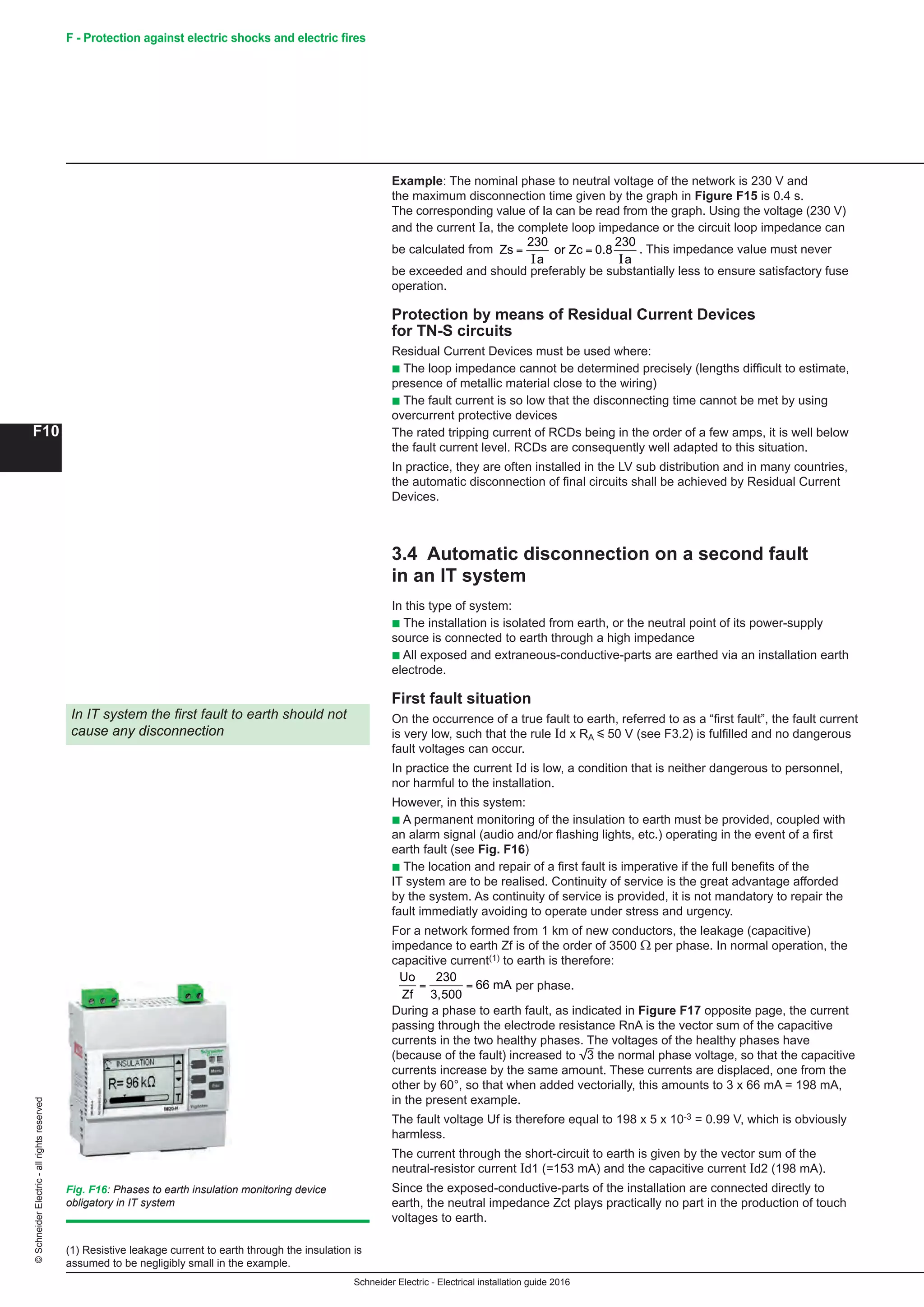
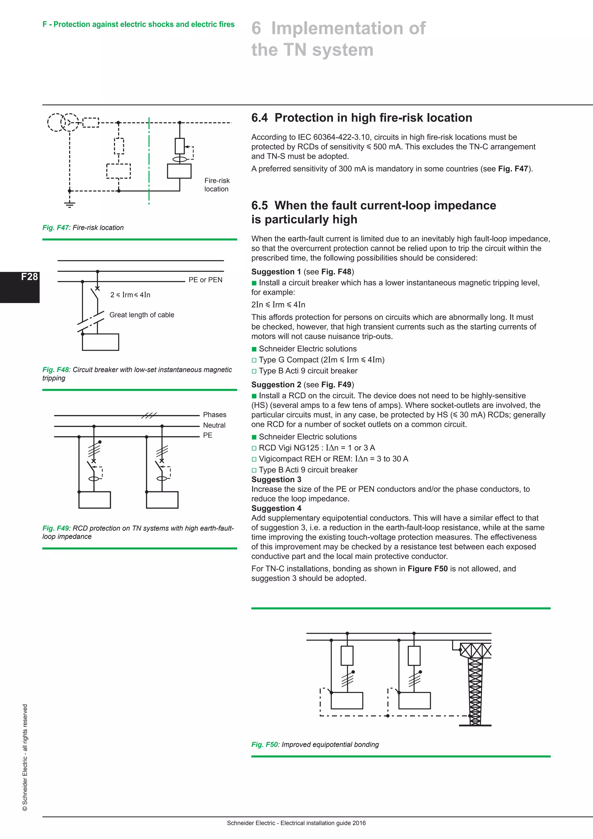
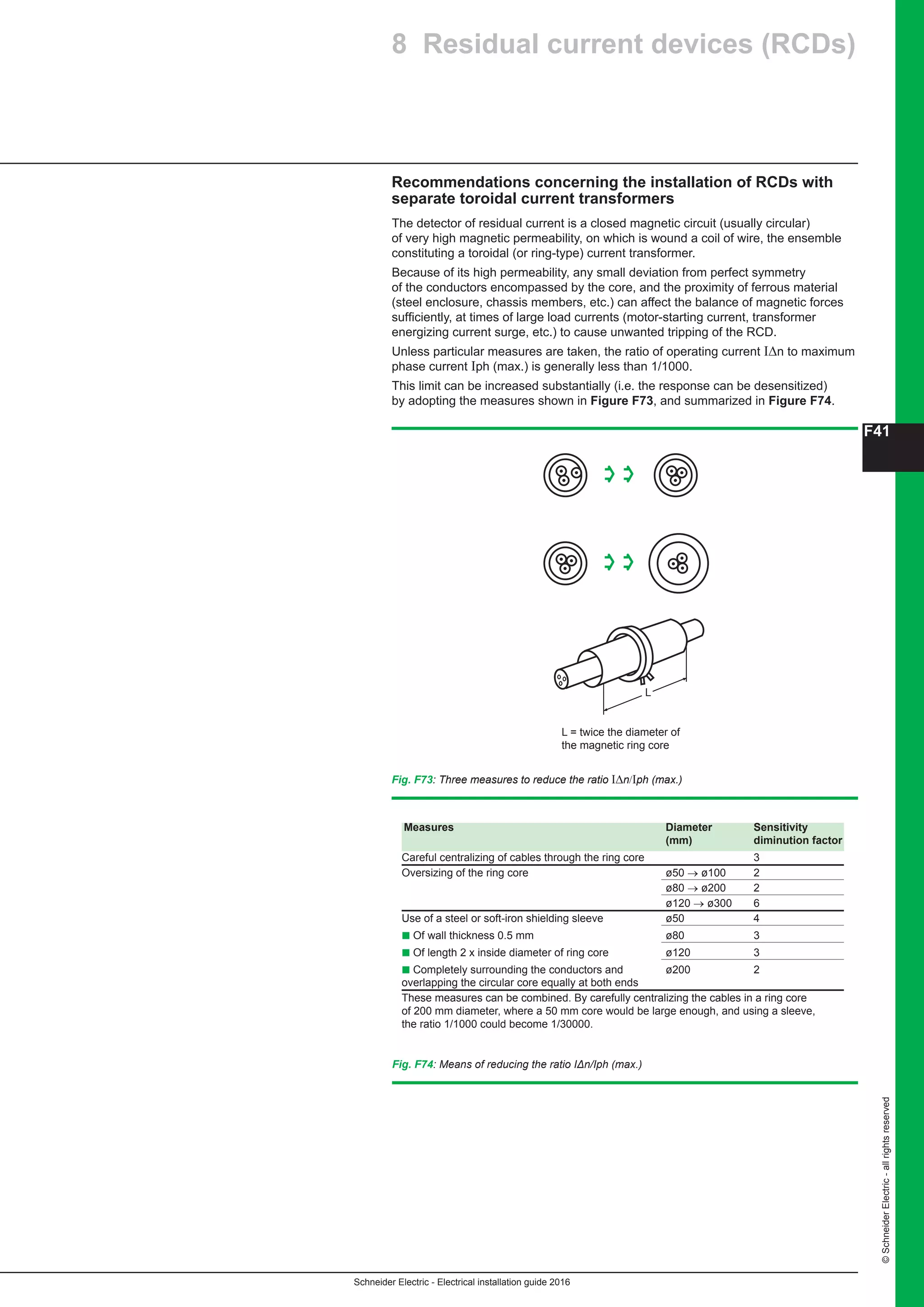
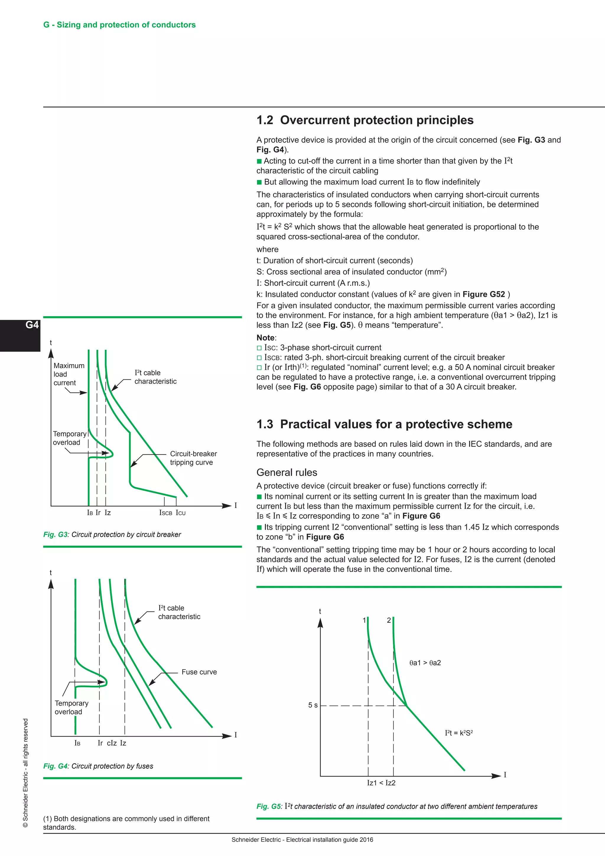
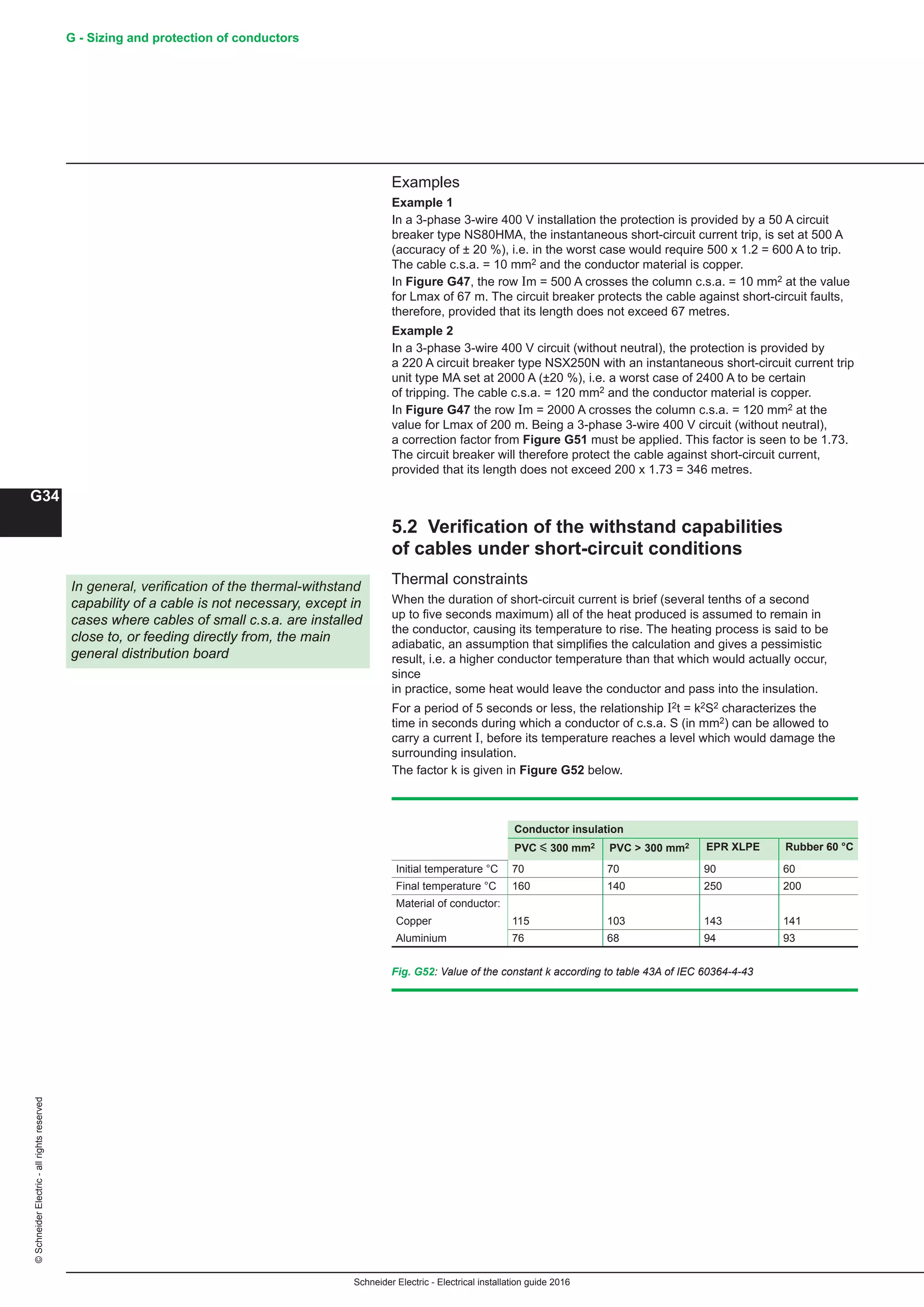
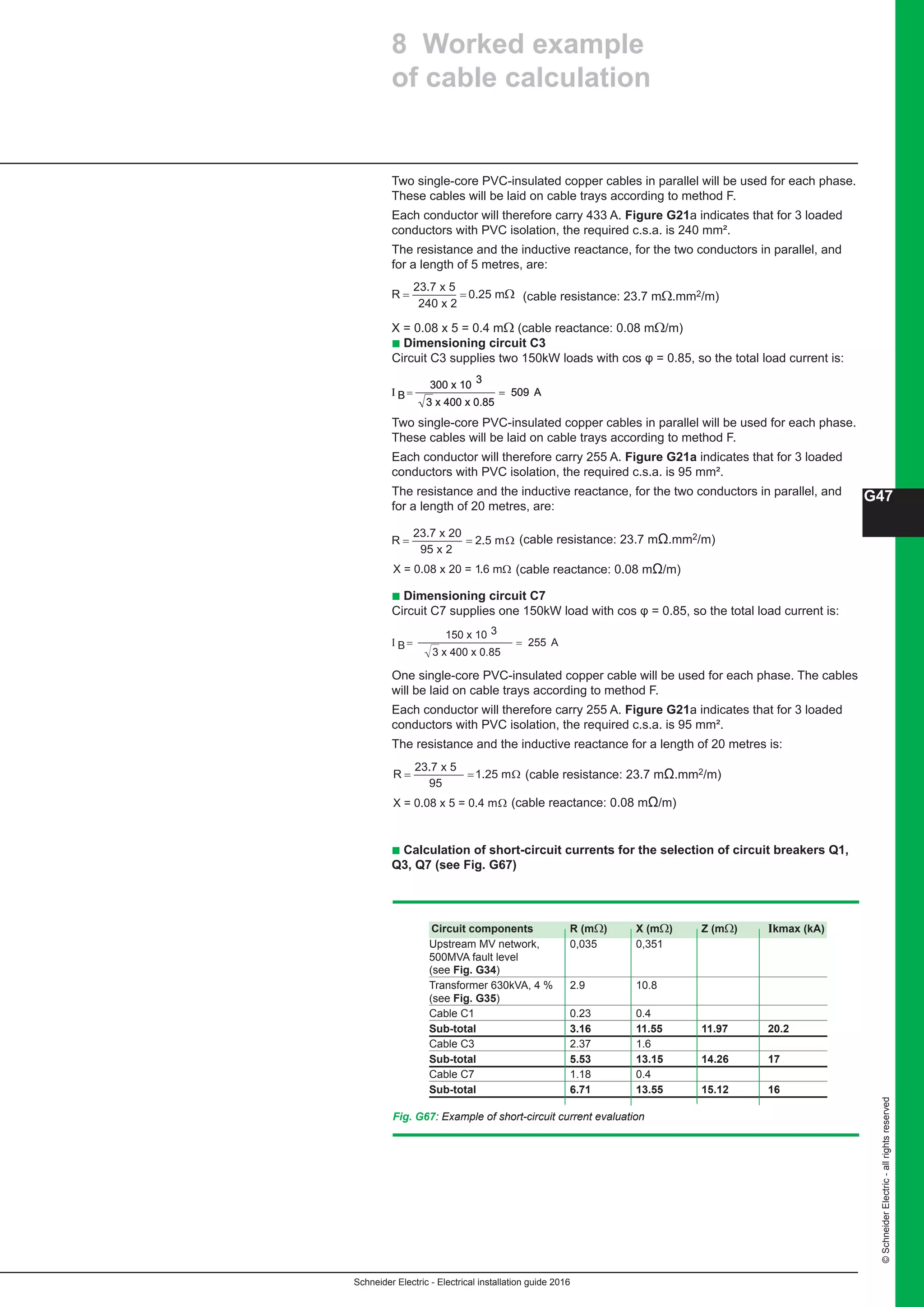
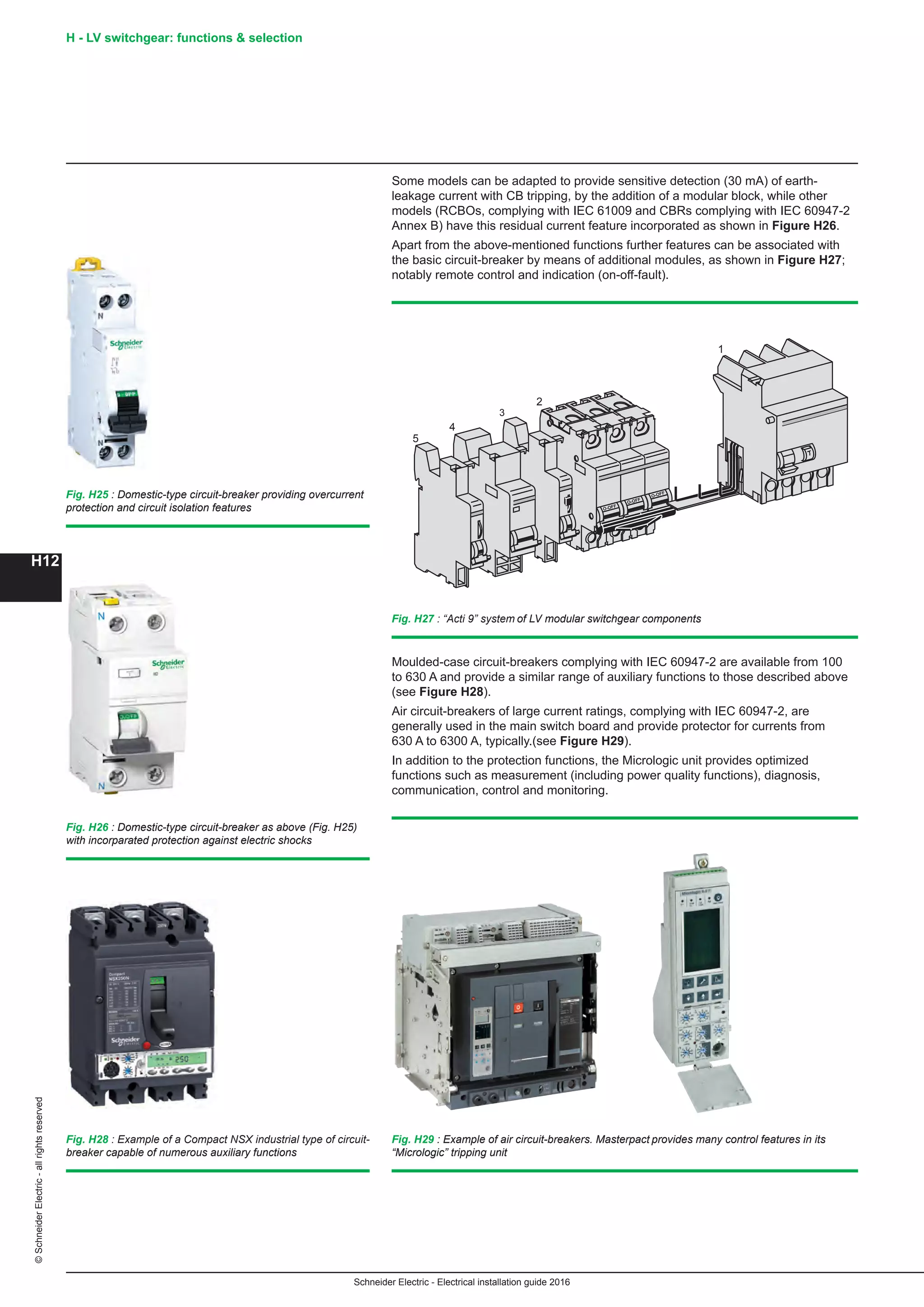
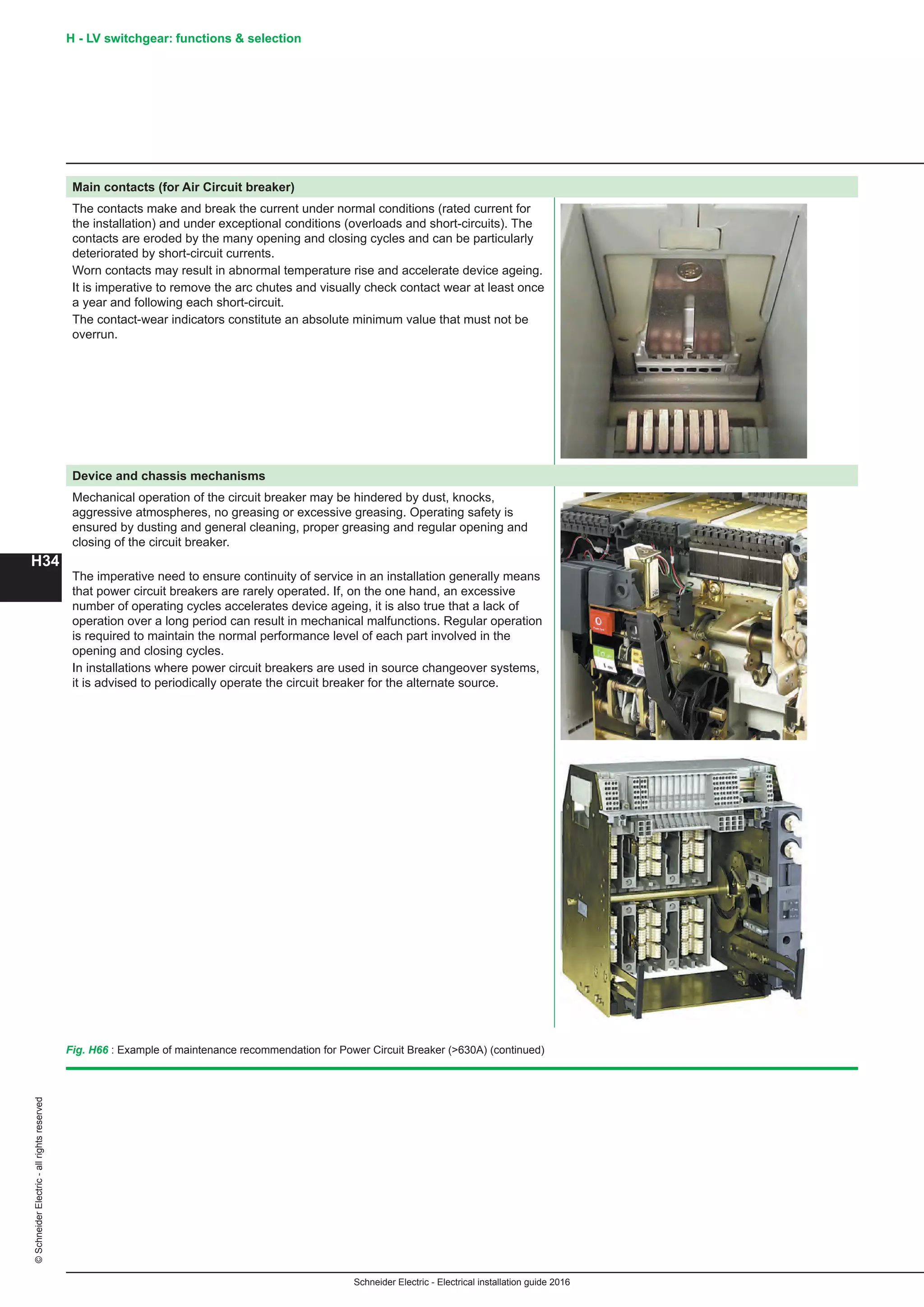
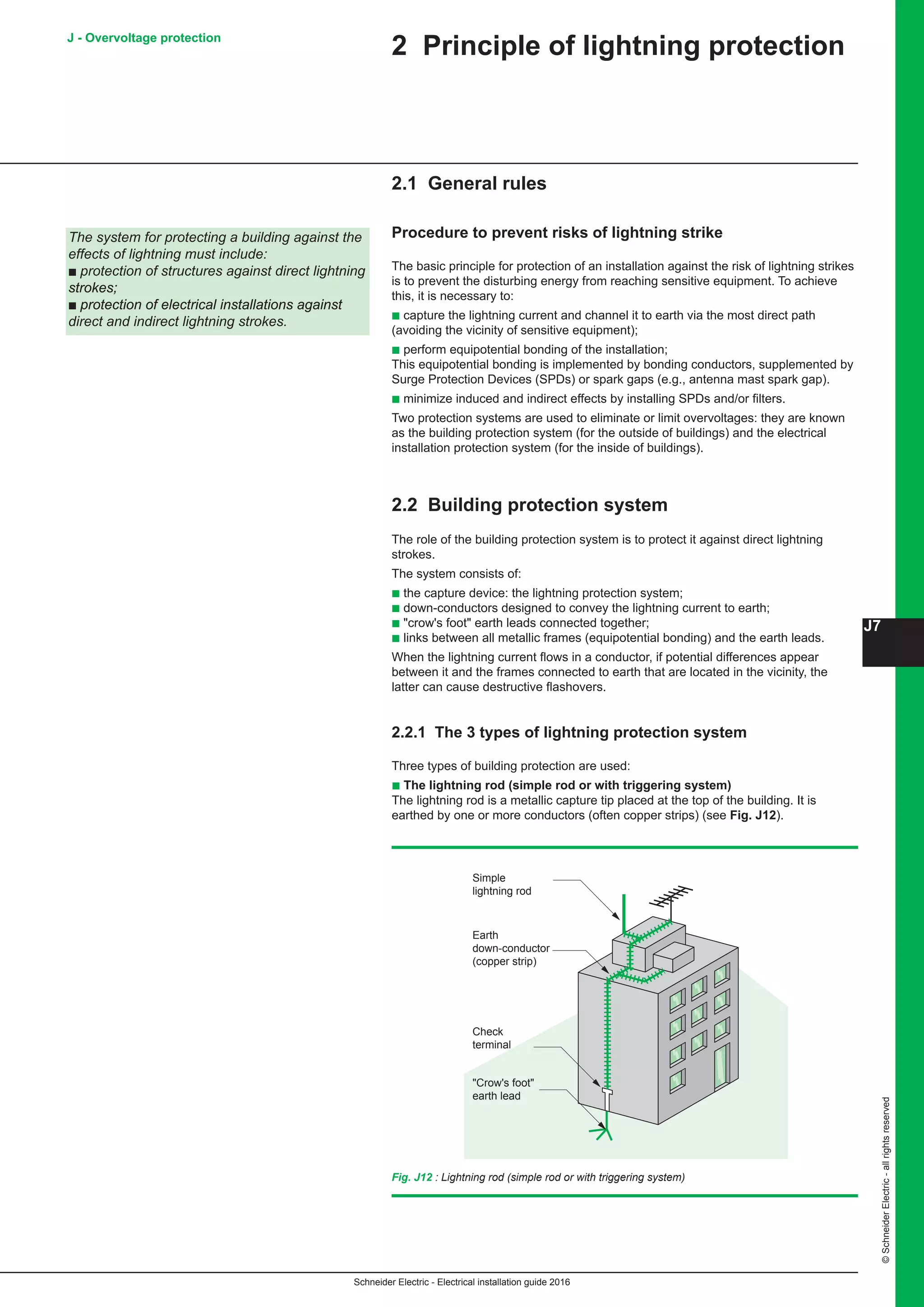
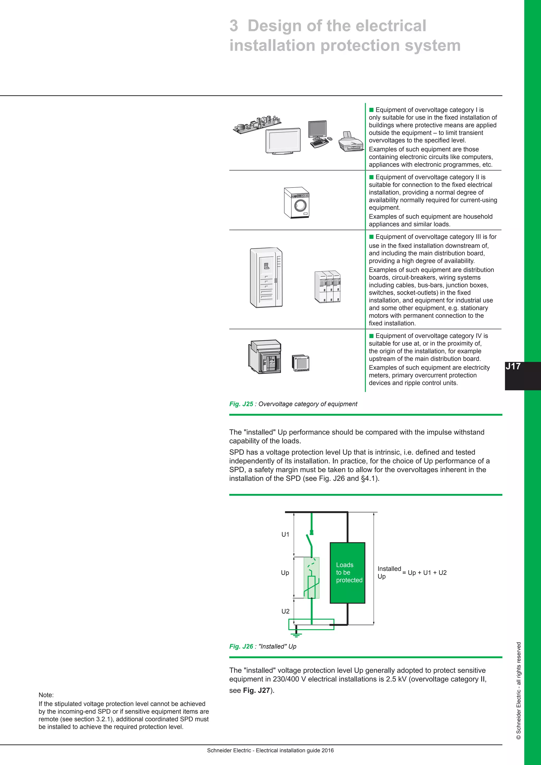
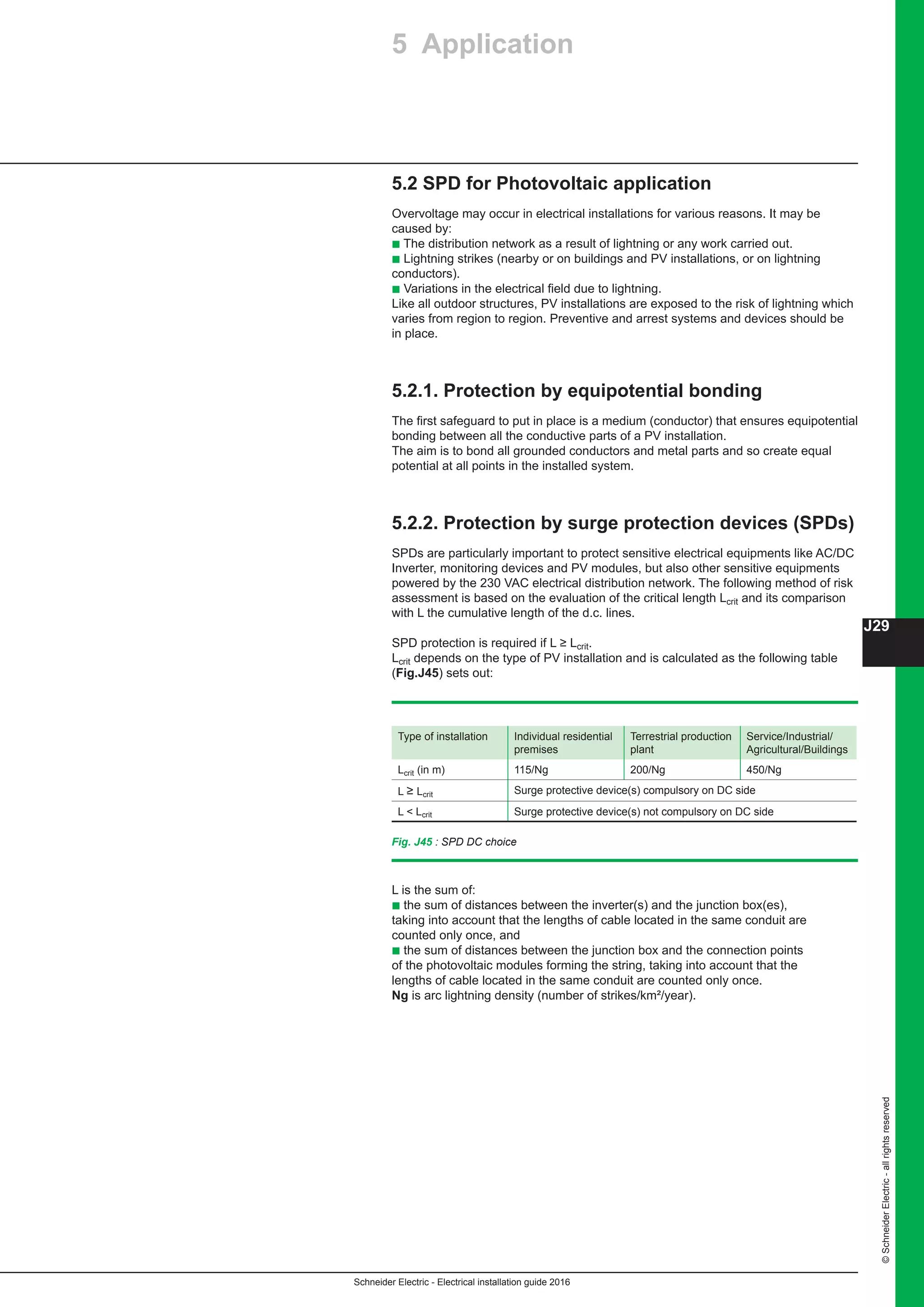
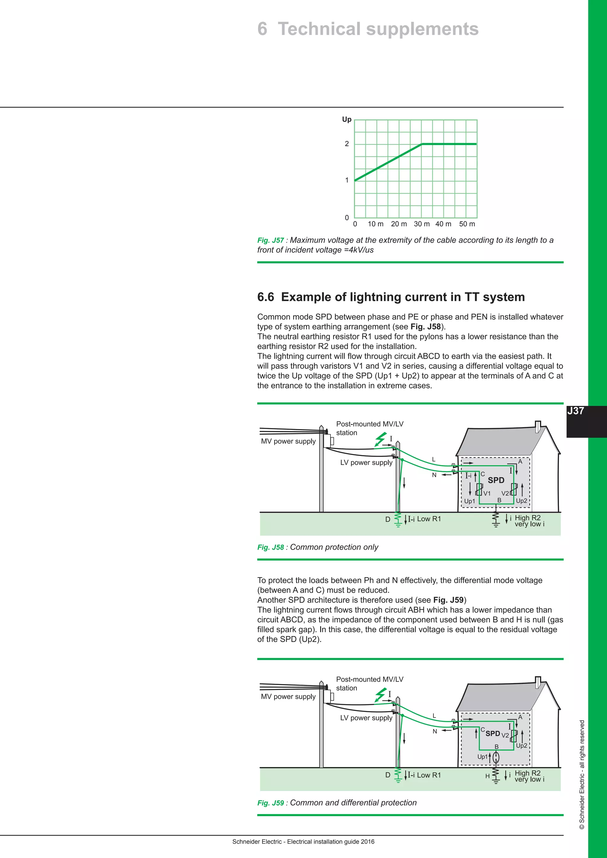
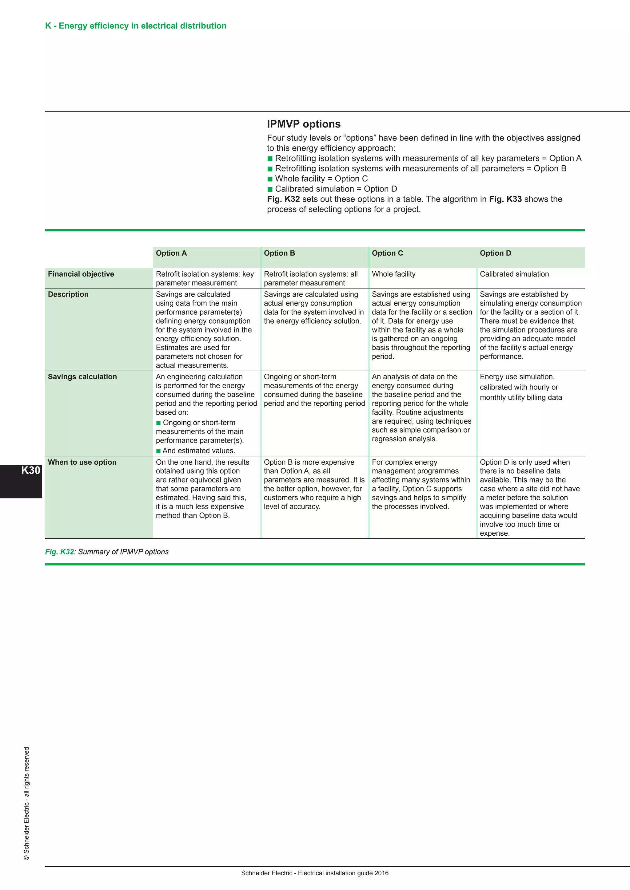
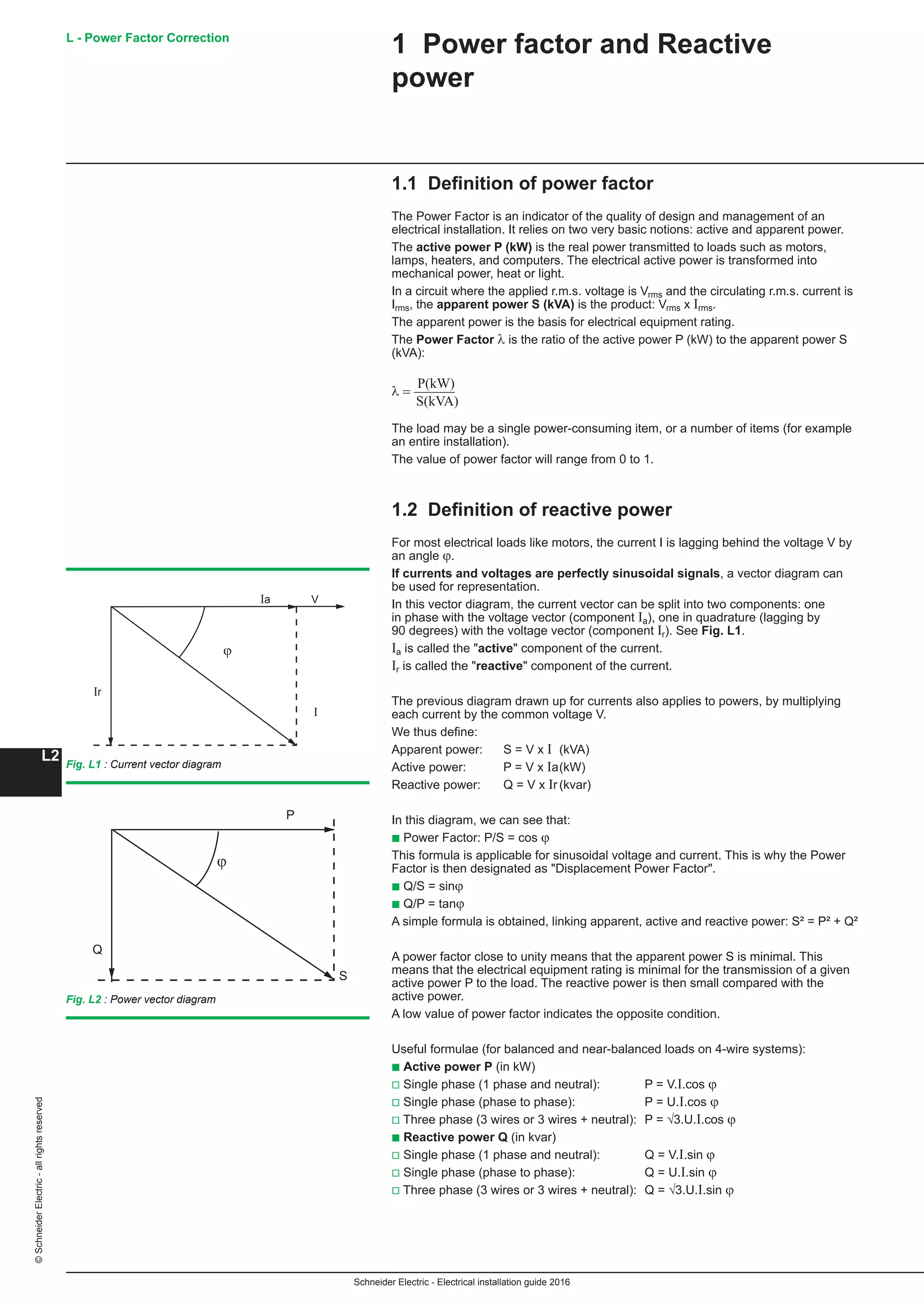
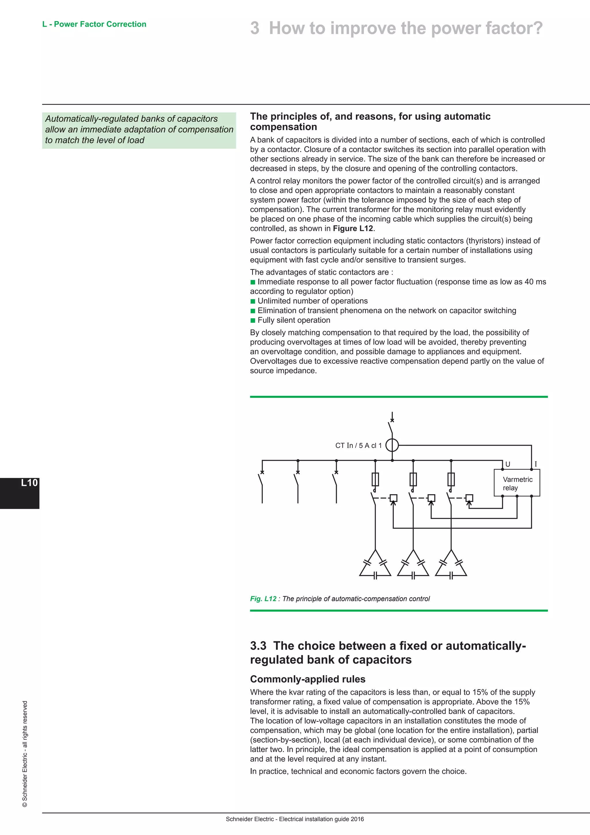
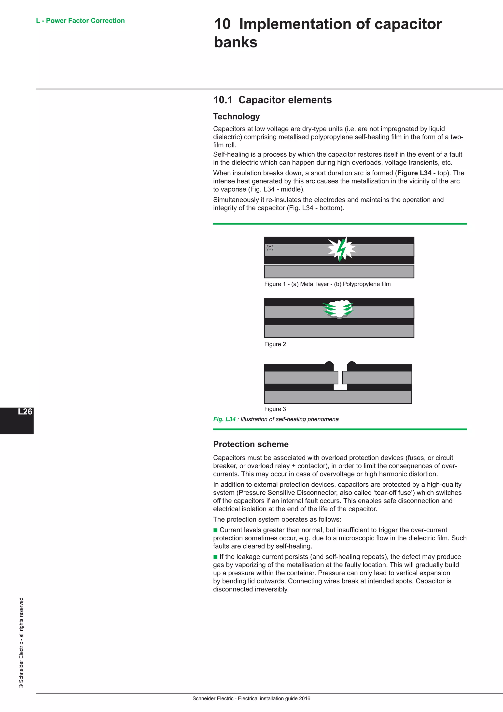
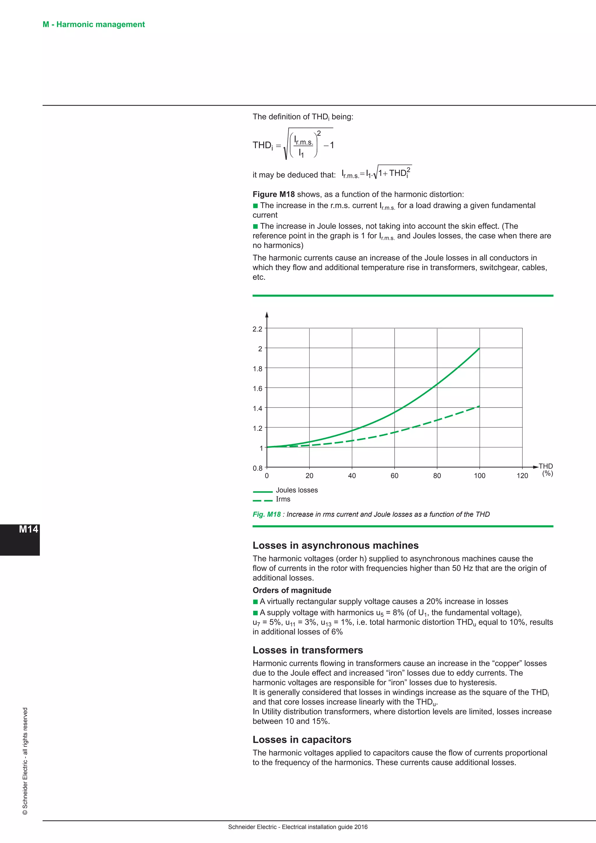
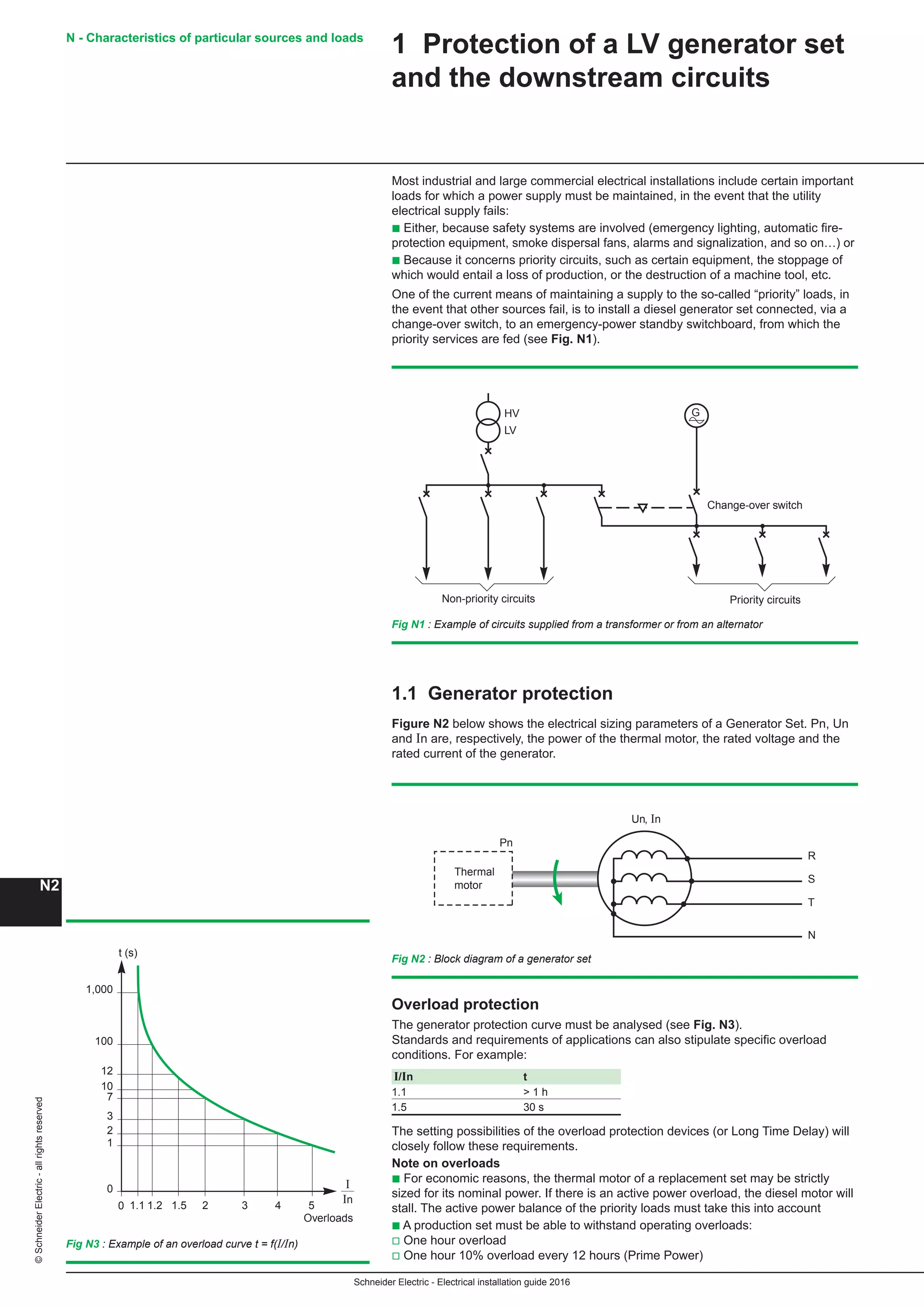
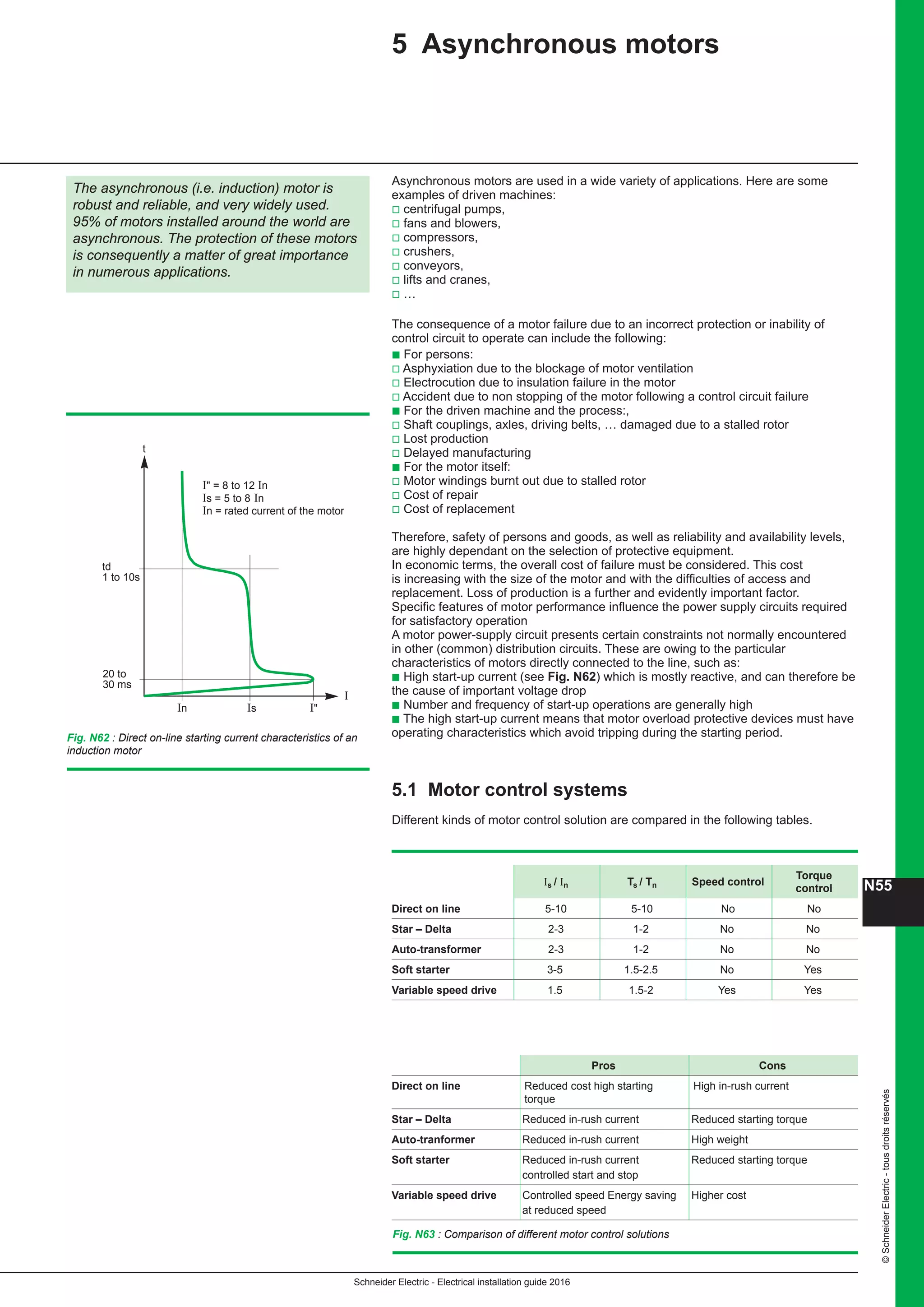
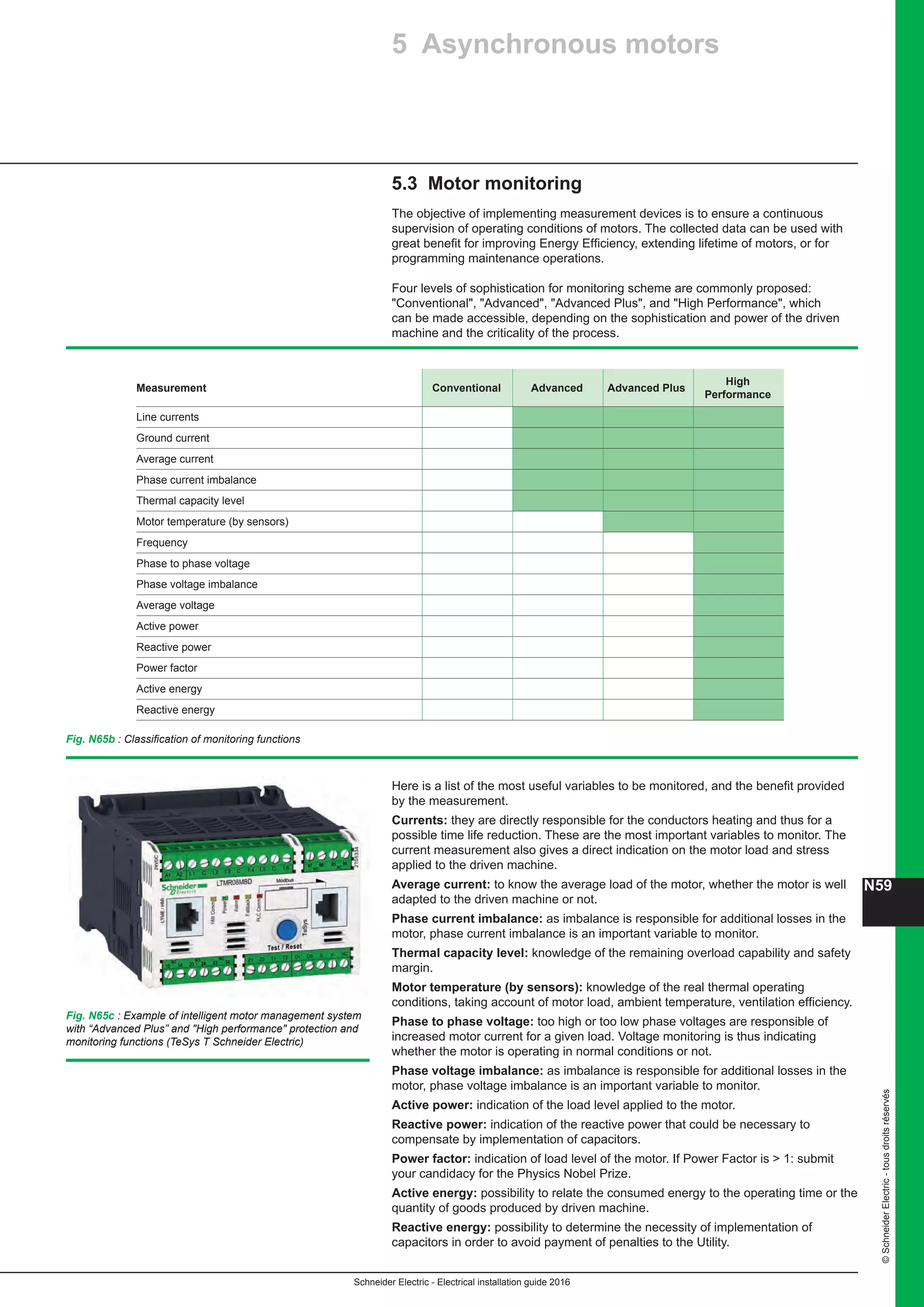
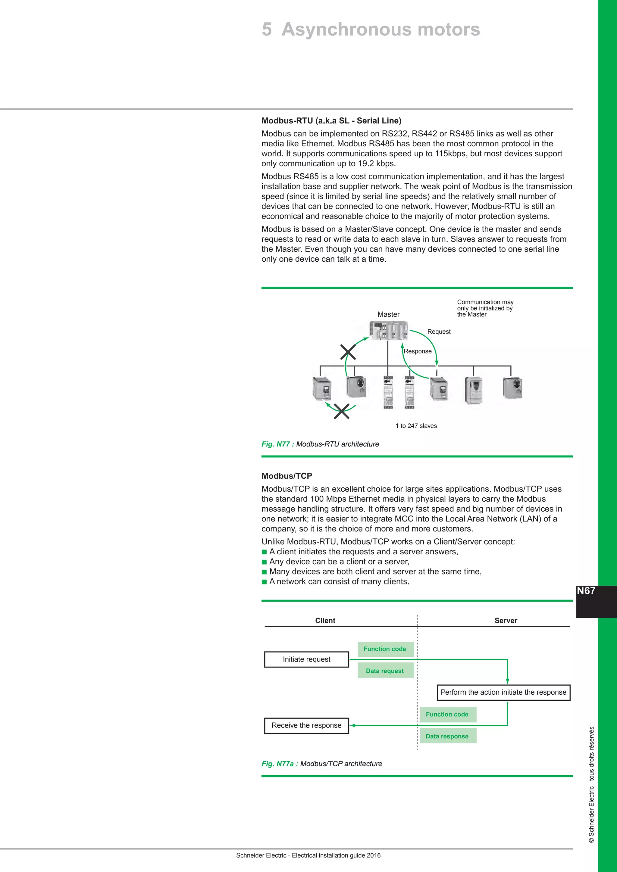
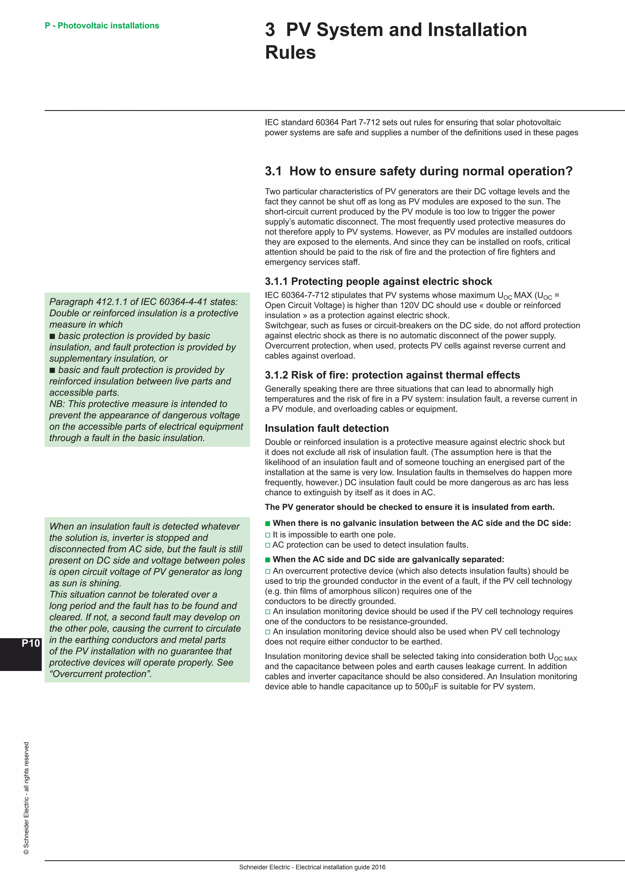
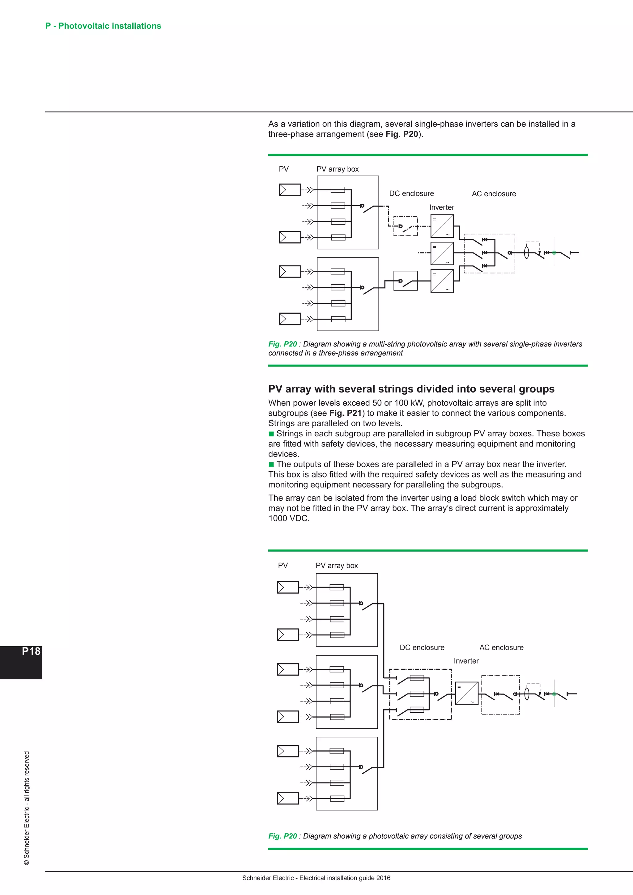
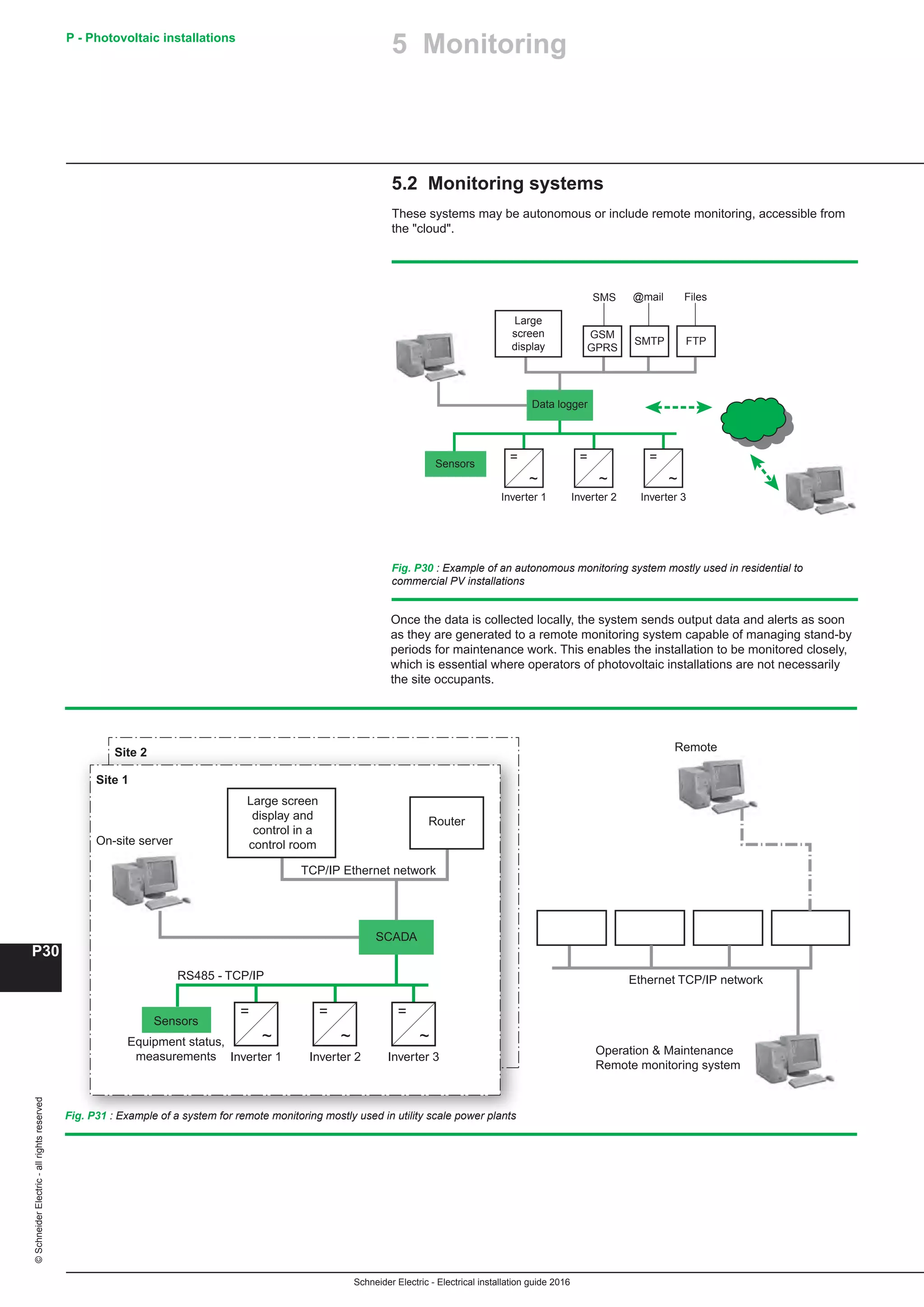
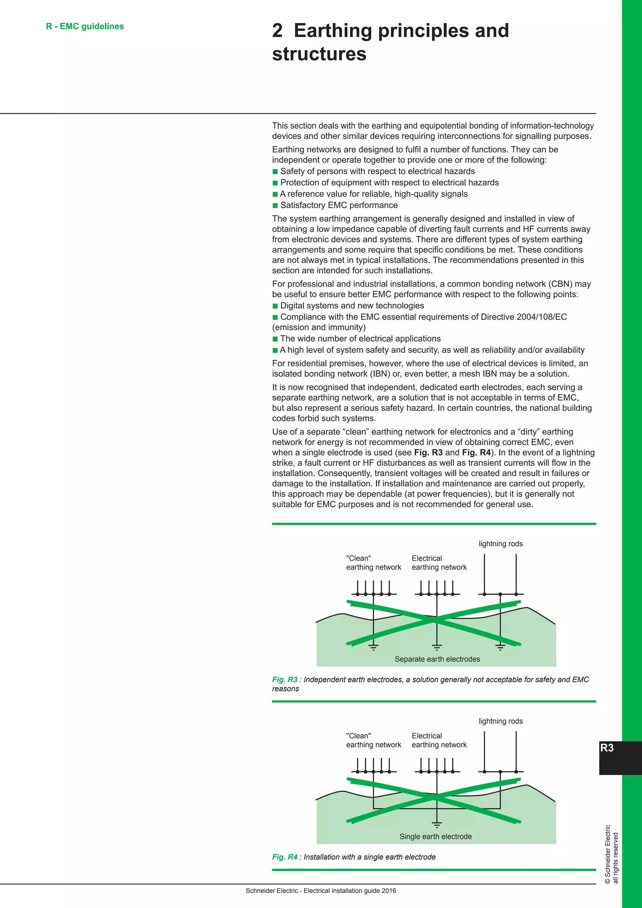
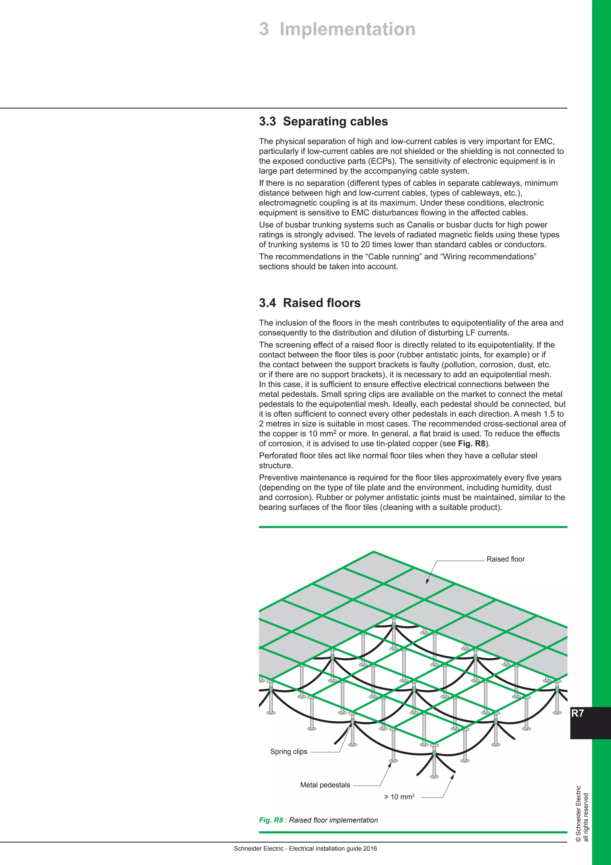
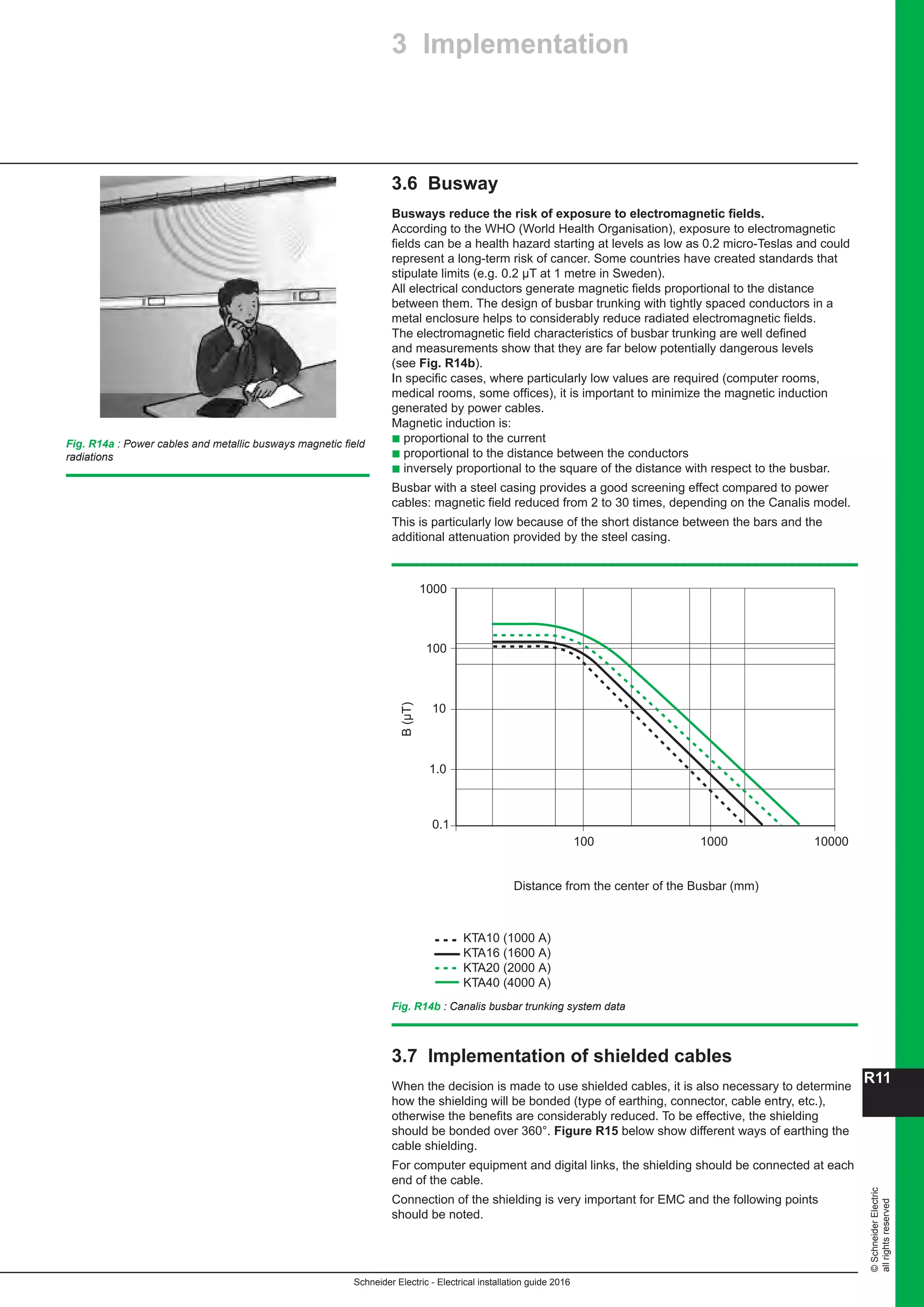
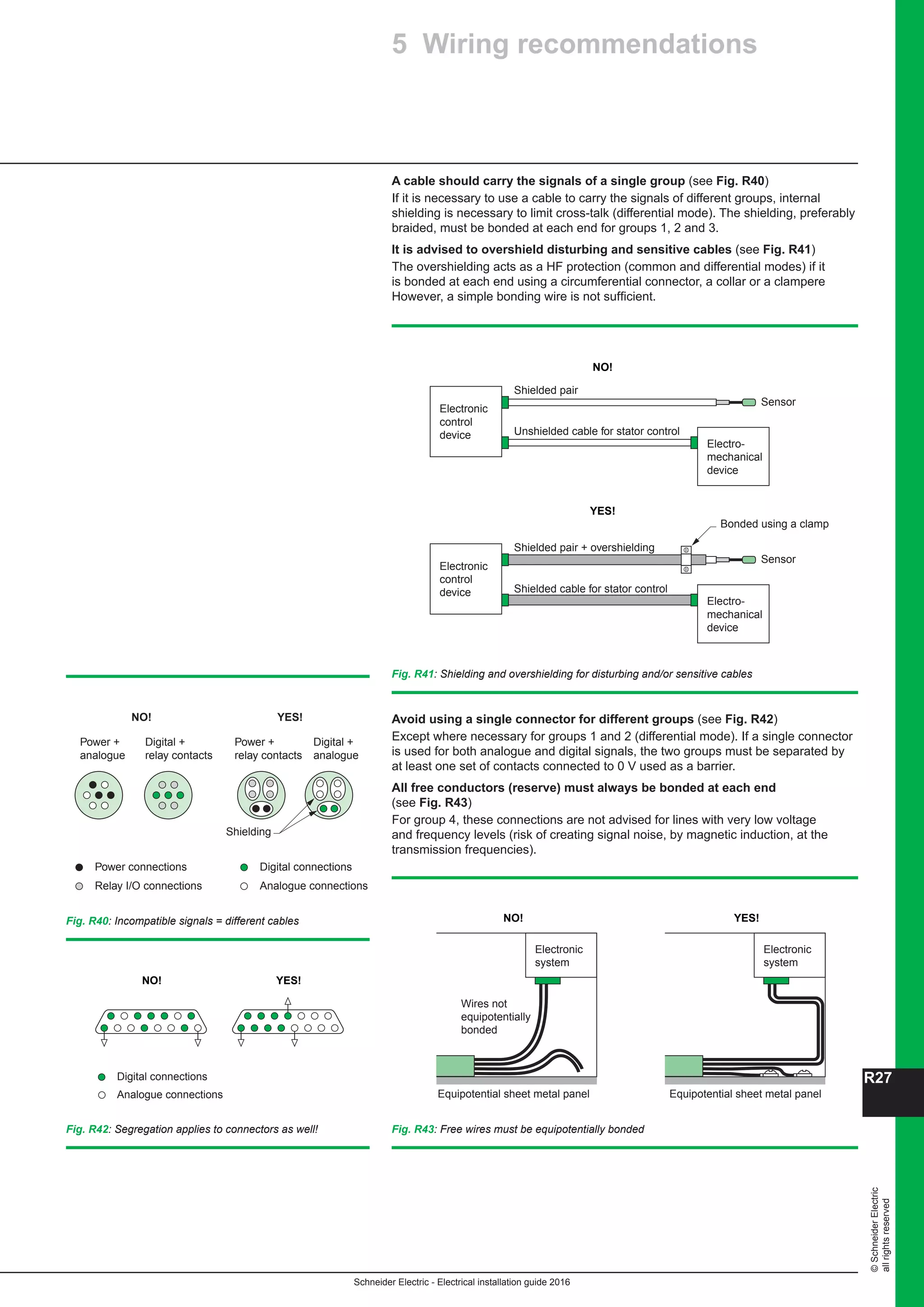
The substations may be situated at ground level, half buried or completely buried
(underground substation), resulting in three types of design (see Fig. B57 and
Fig. B58).
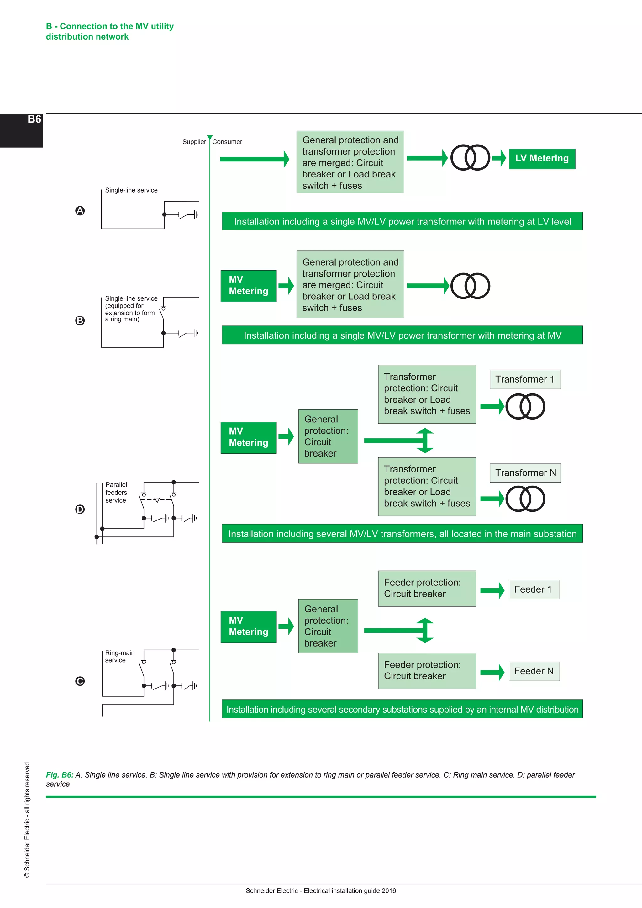
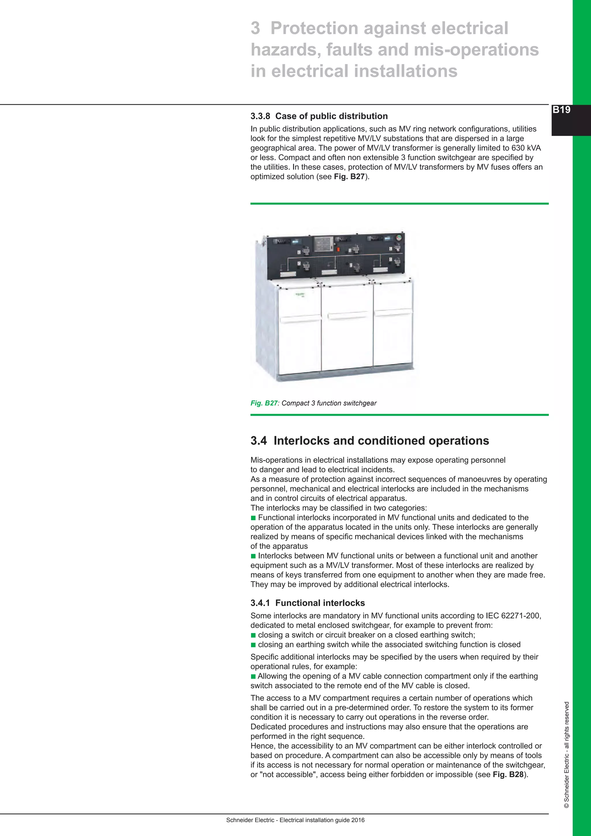
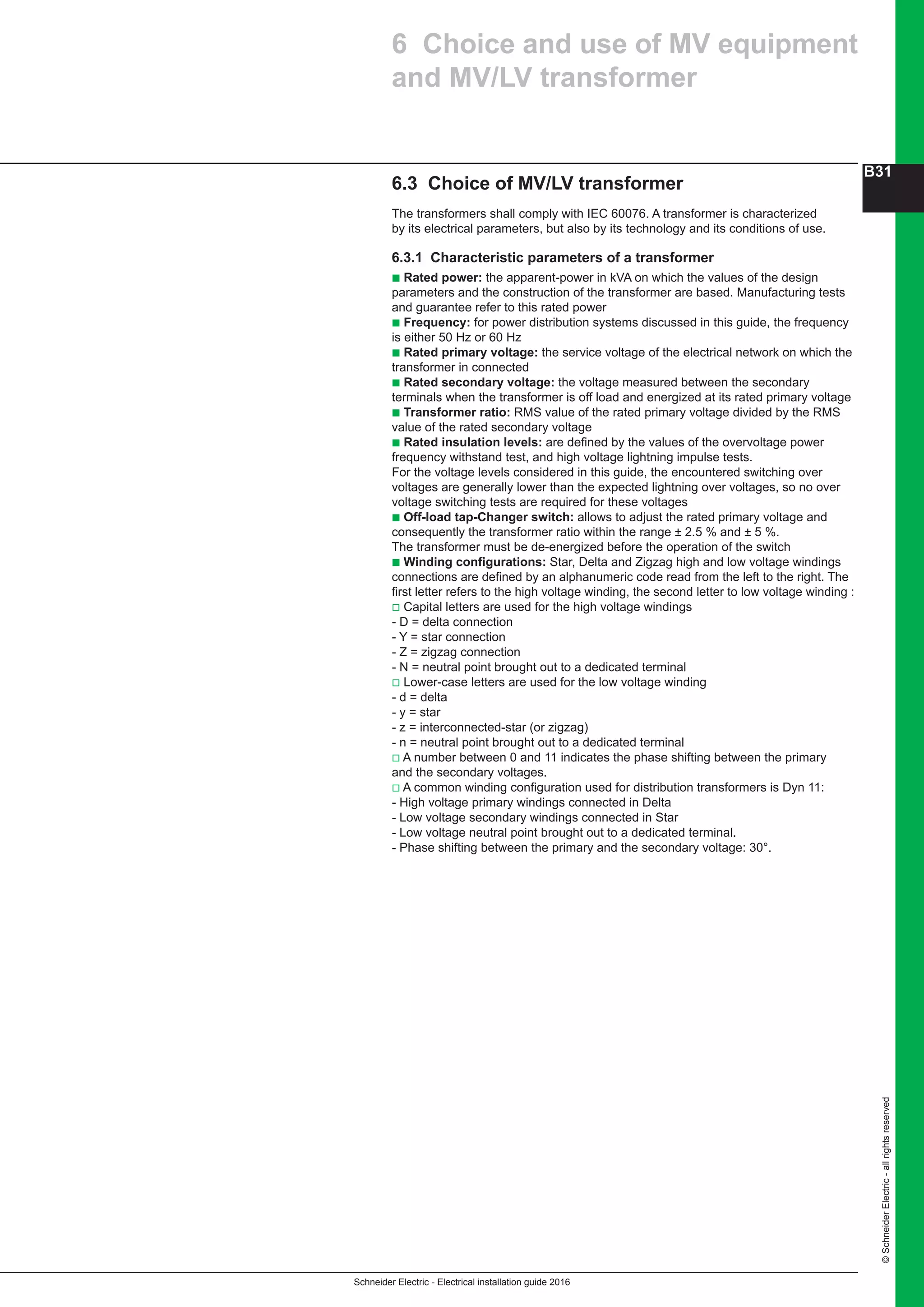
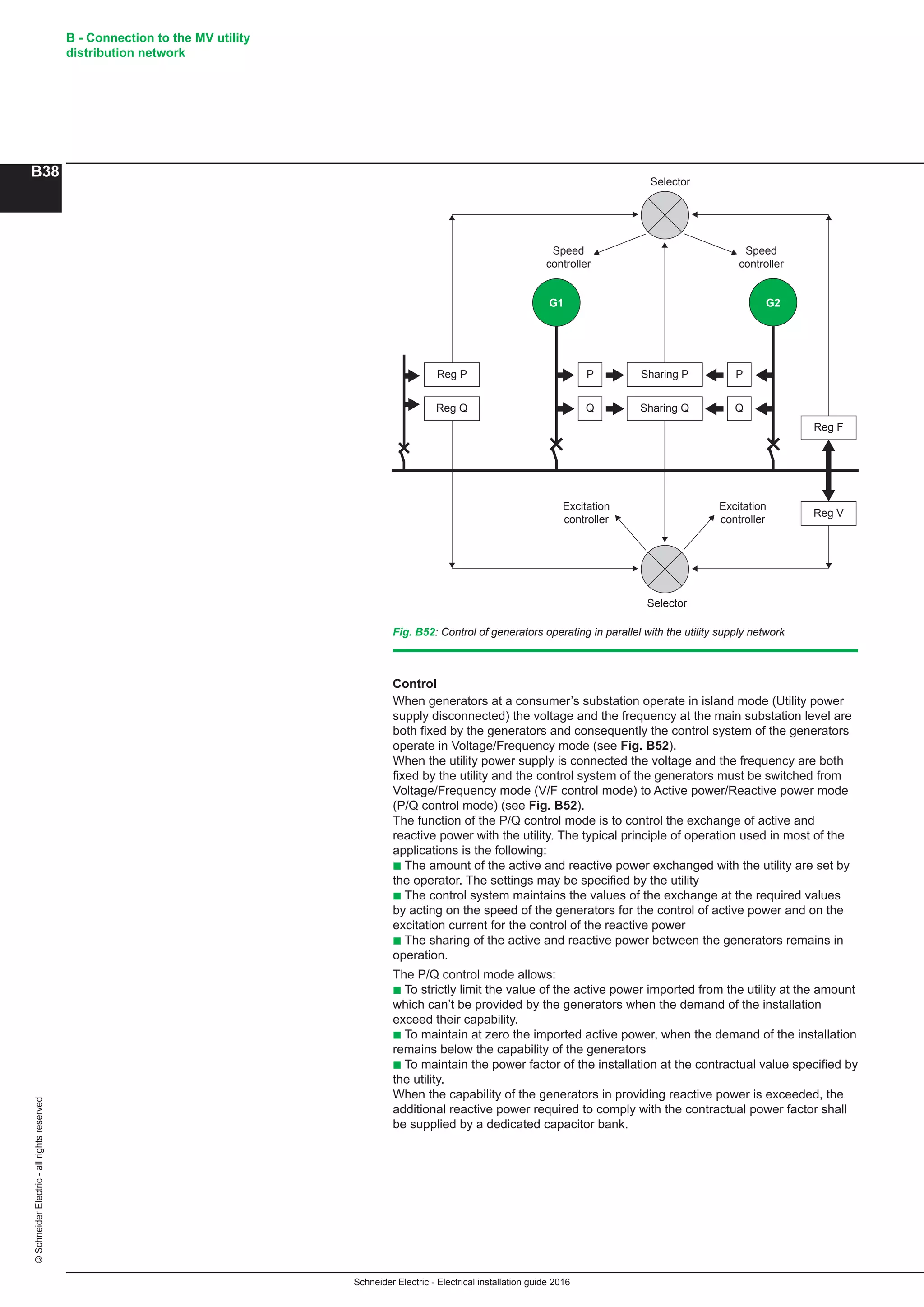
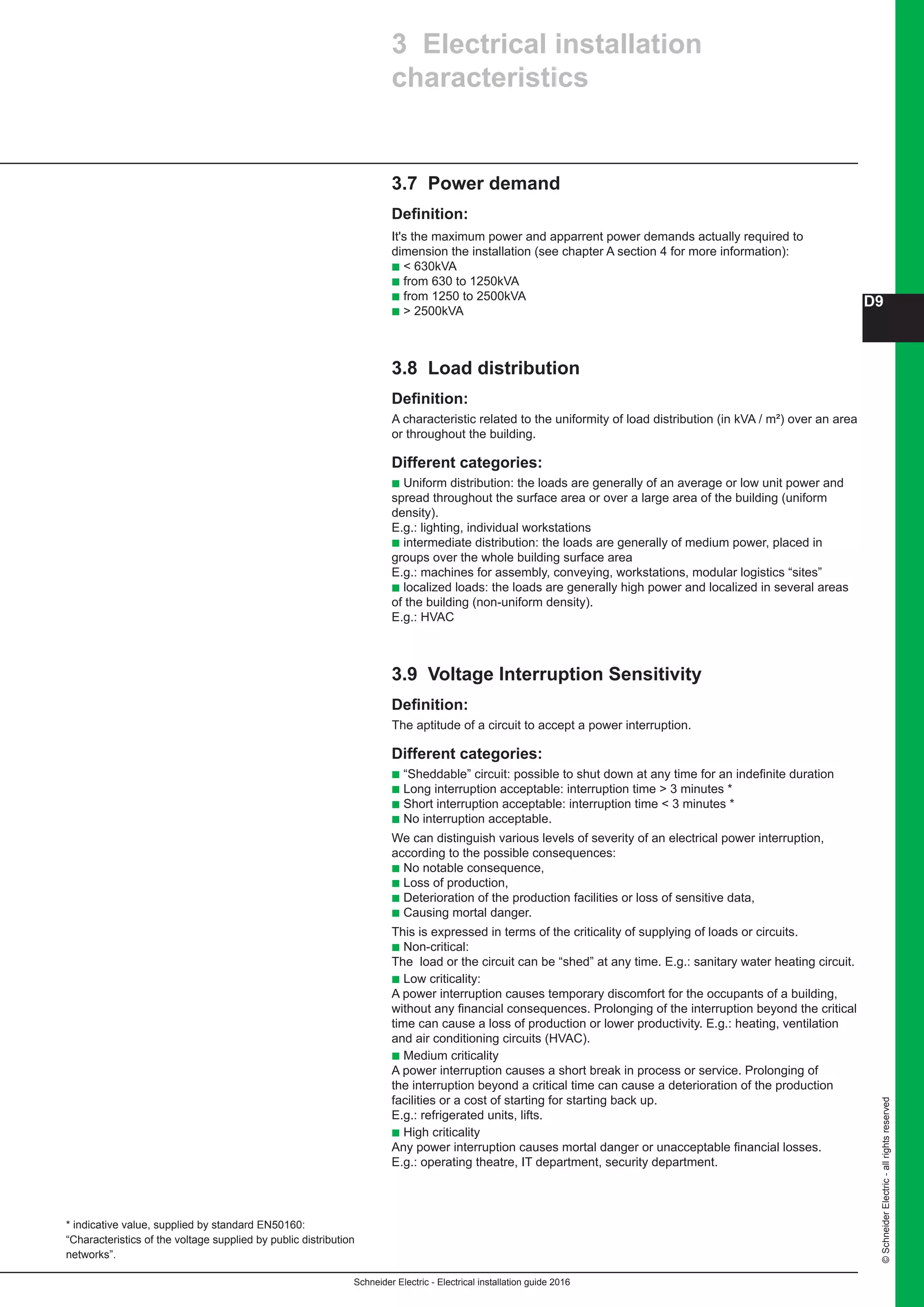
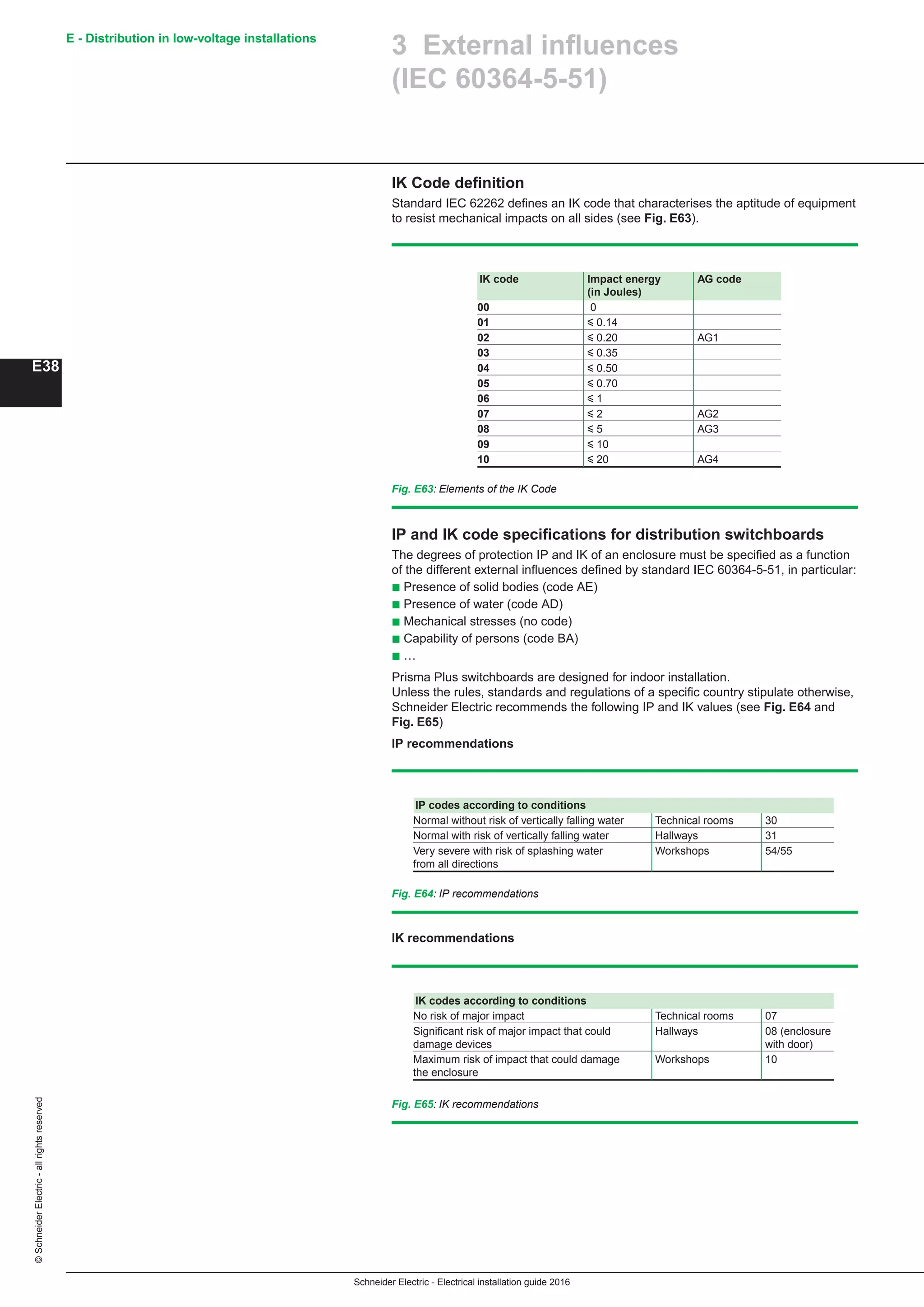
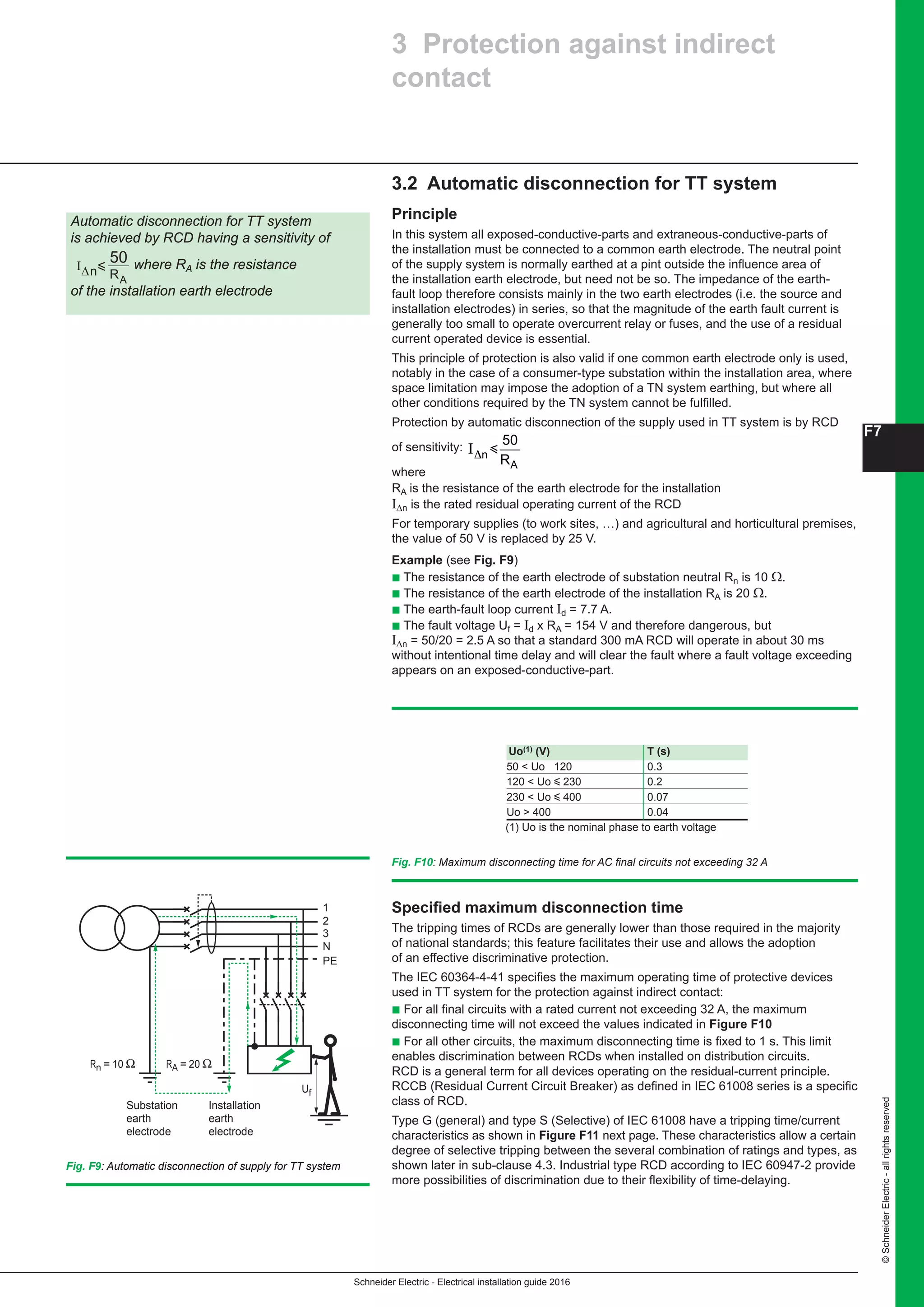
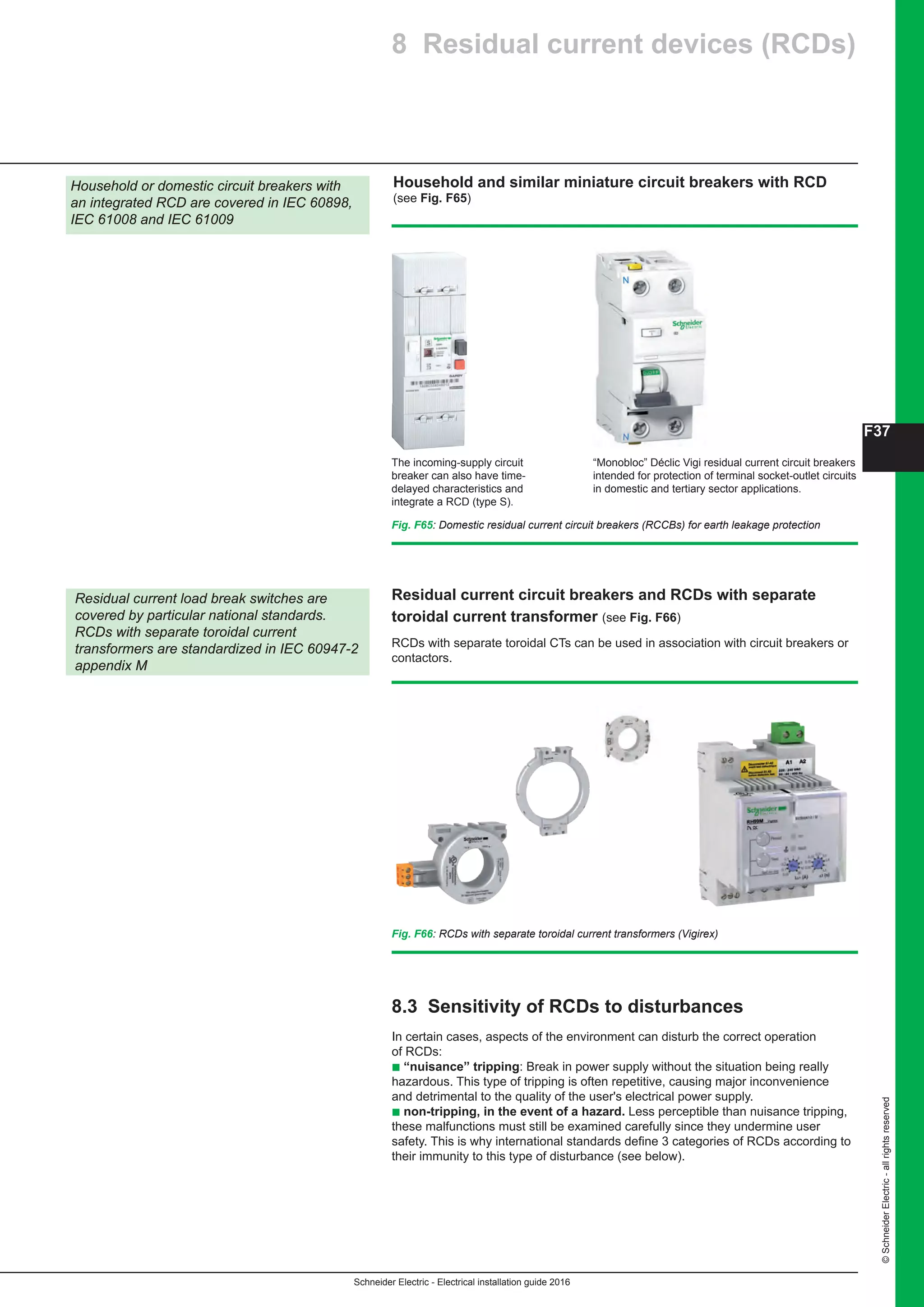
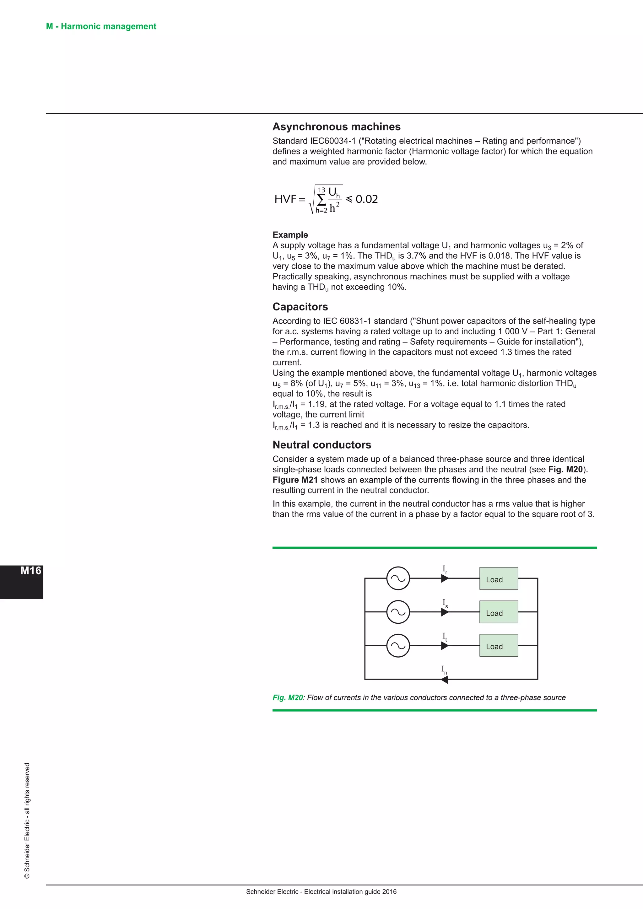
8.3.2 Outdoor substation without enclosure (see Fig. B59)
This kind of outdoor substations based on weatherproof equipment is commonly
used in countries such as UK and India for example.
These substations are generally included in MV rings and include:
b Two functional units dedicated to the connection of the substation to the ring
b One functional unit for the supply and the protection of the MV/LV power
transformer generally done by a circuit breaker unit
b One single MV/LV Power transformer
b One LV distribution panel.
The transformer and the LV panel can be installed in dedicated outdoor type
housing.
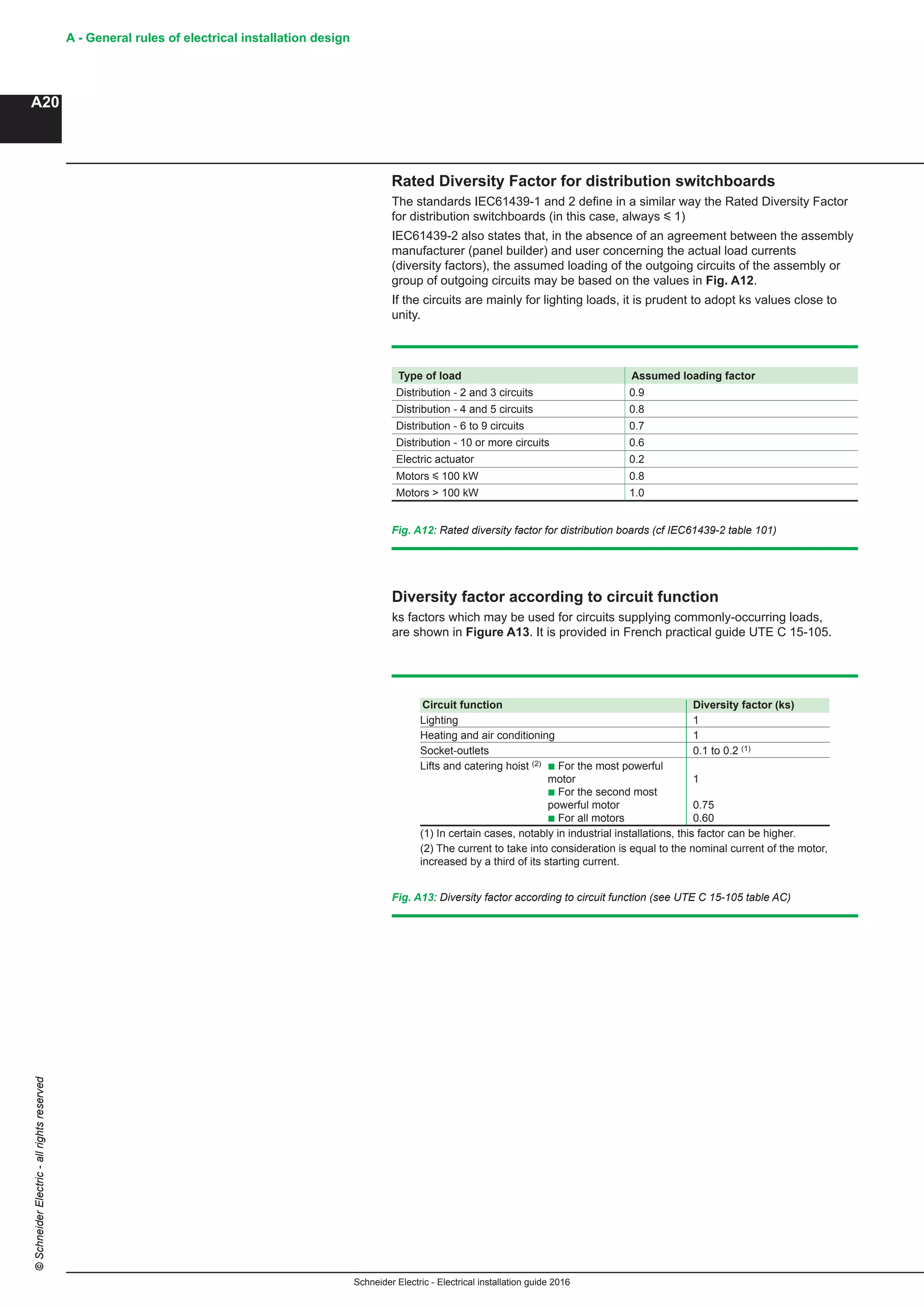
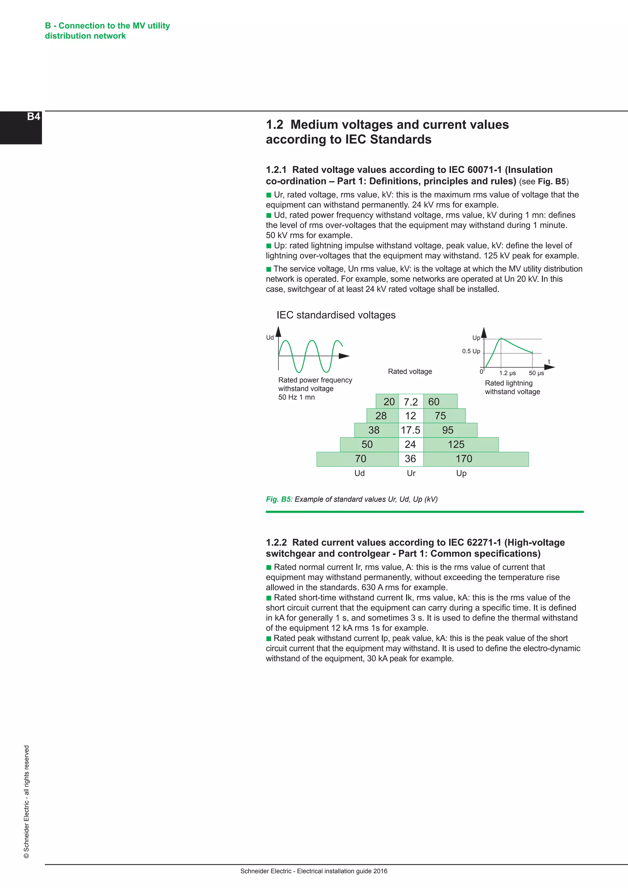
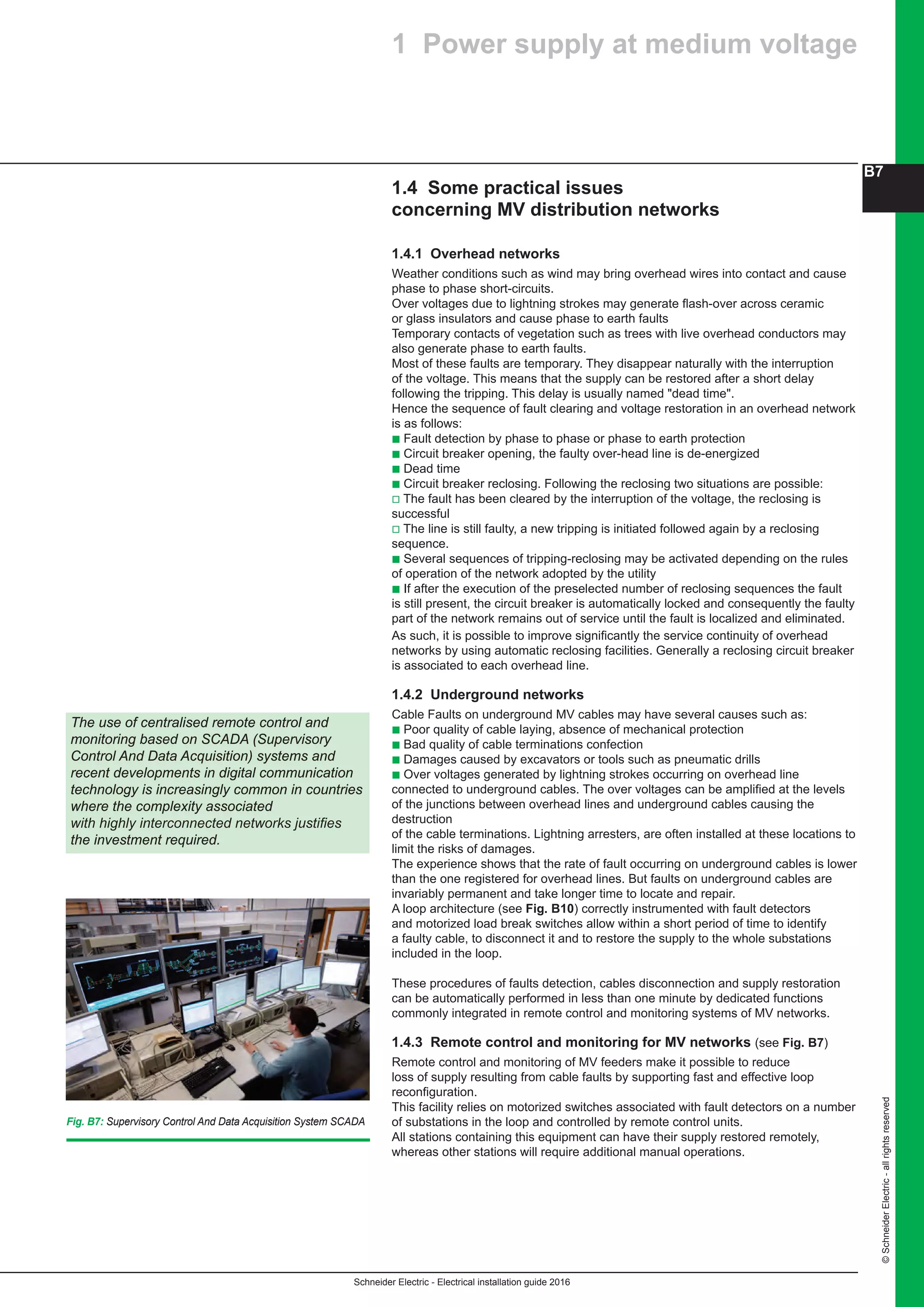
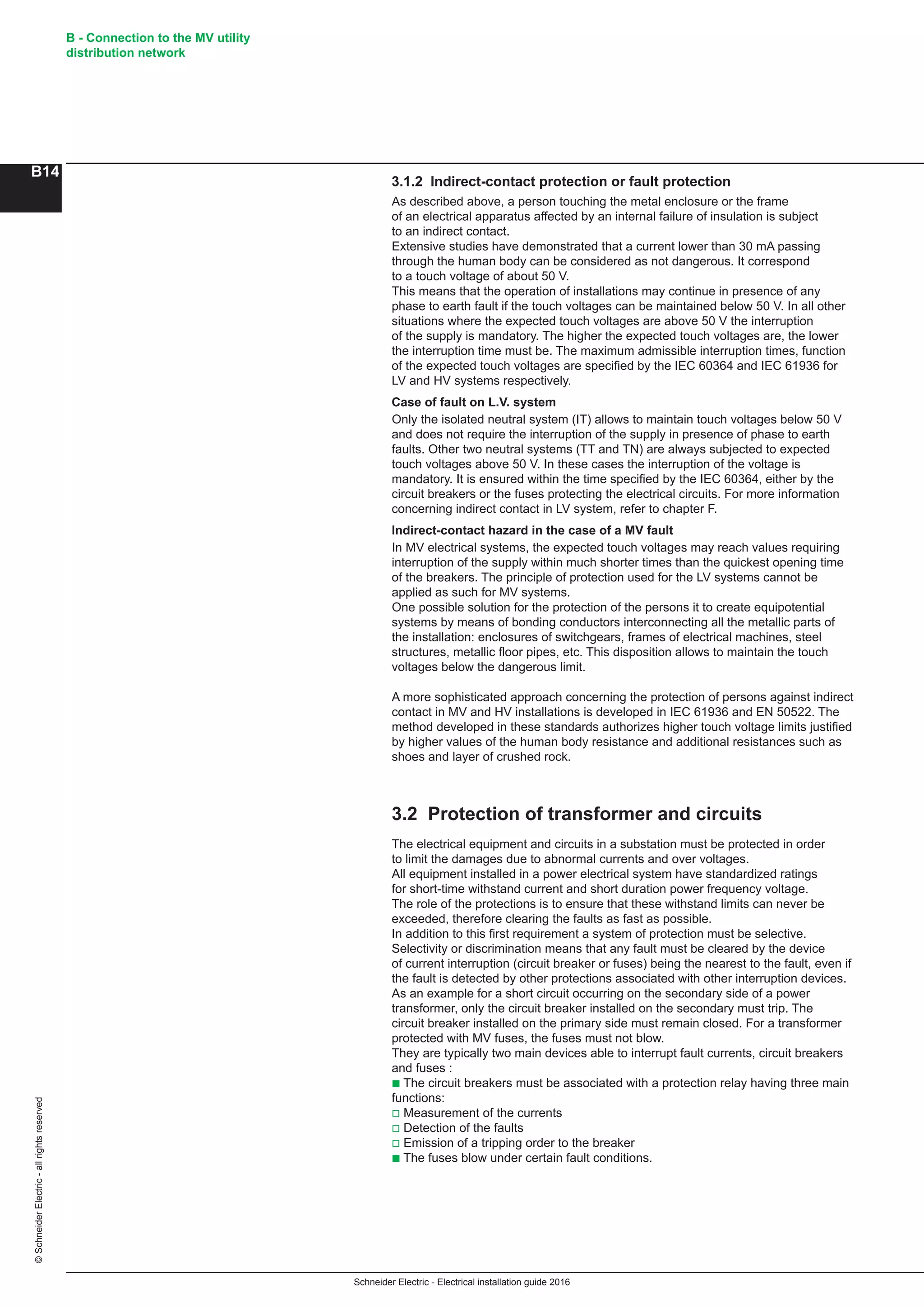
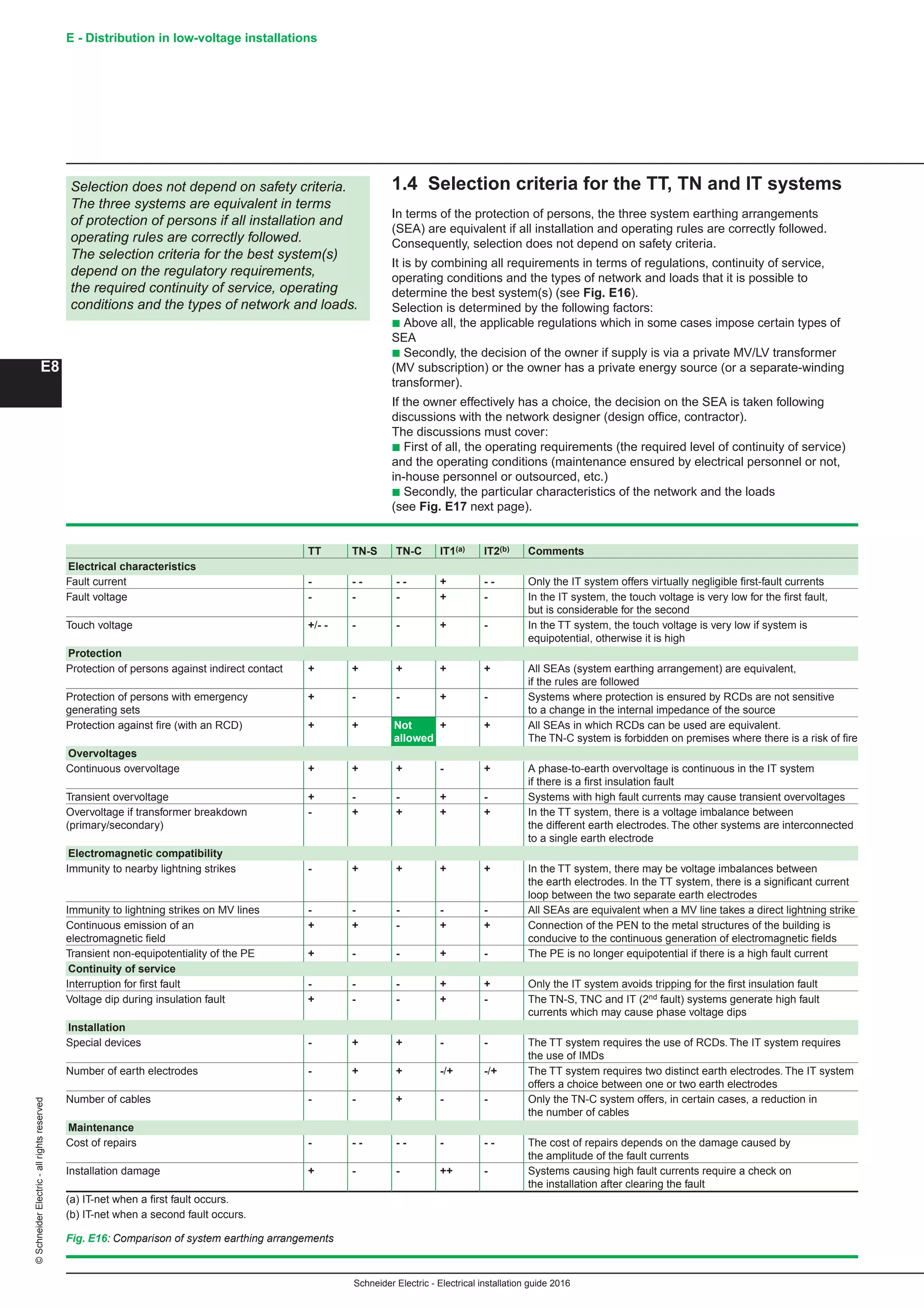
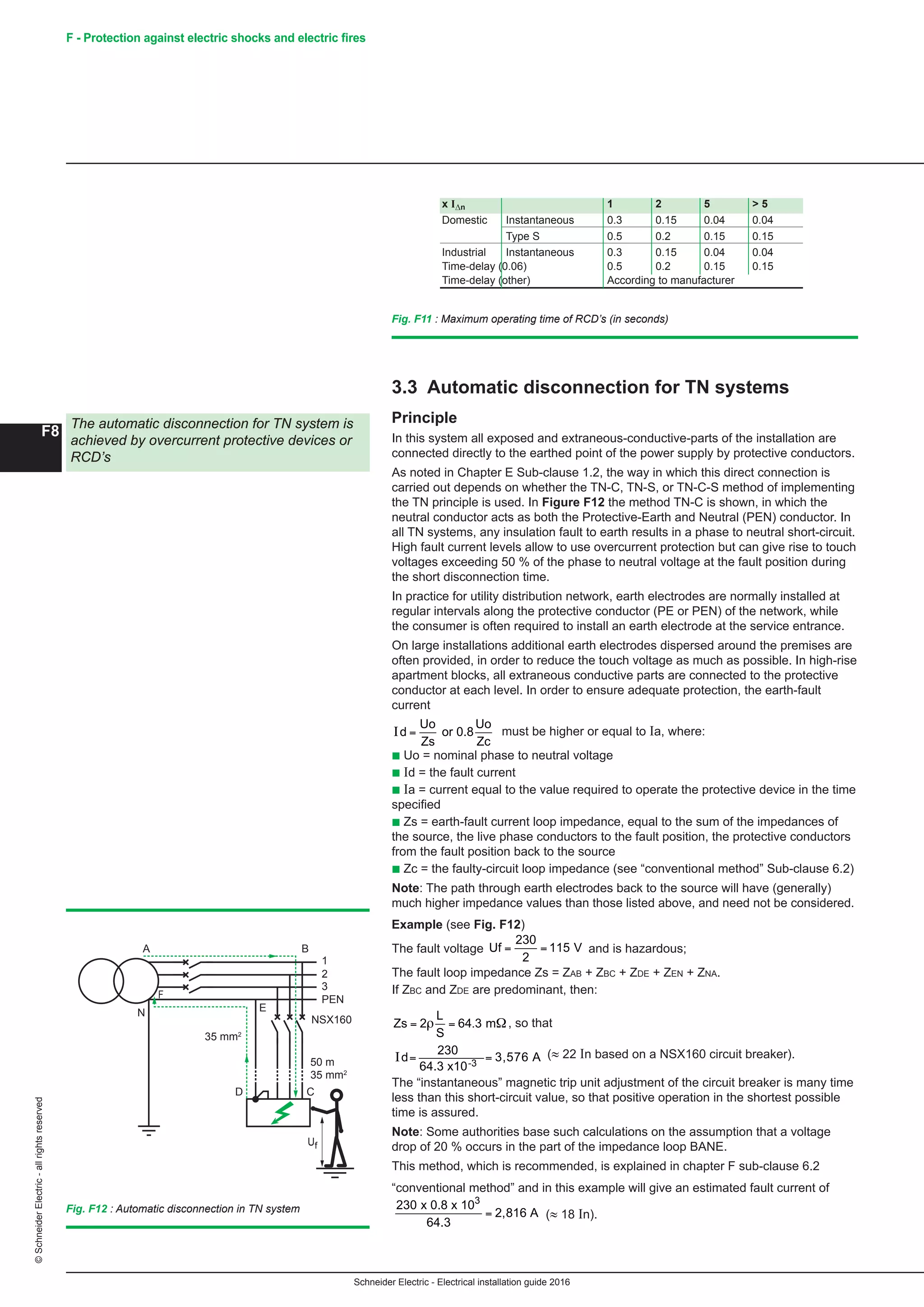
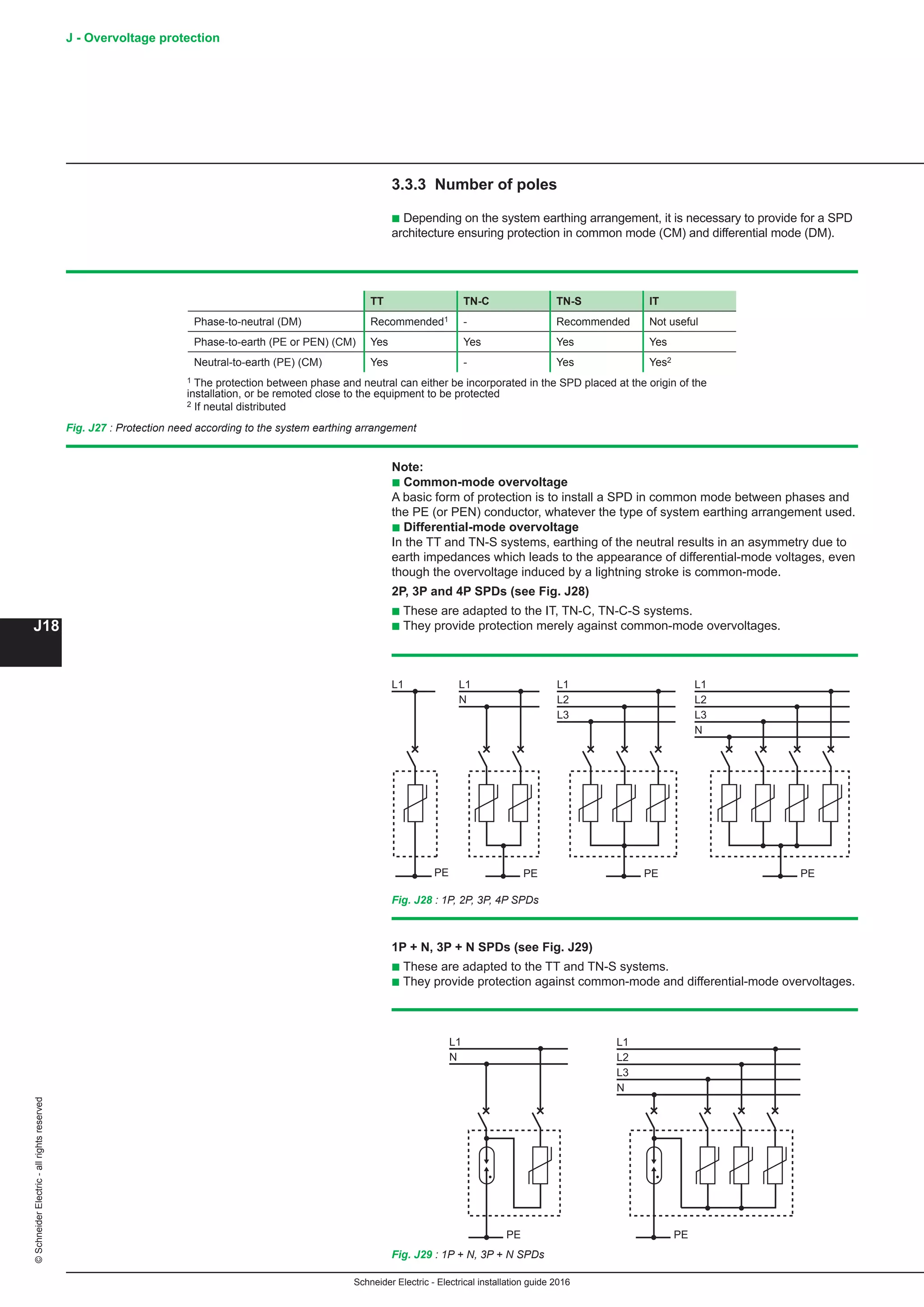
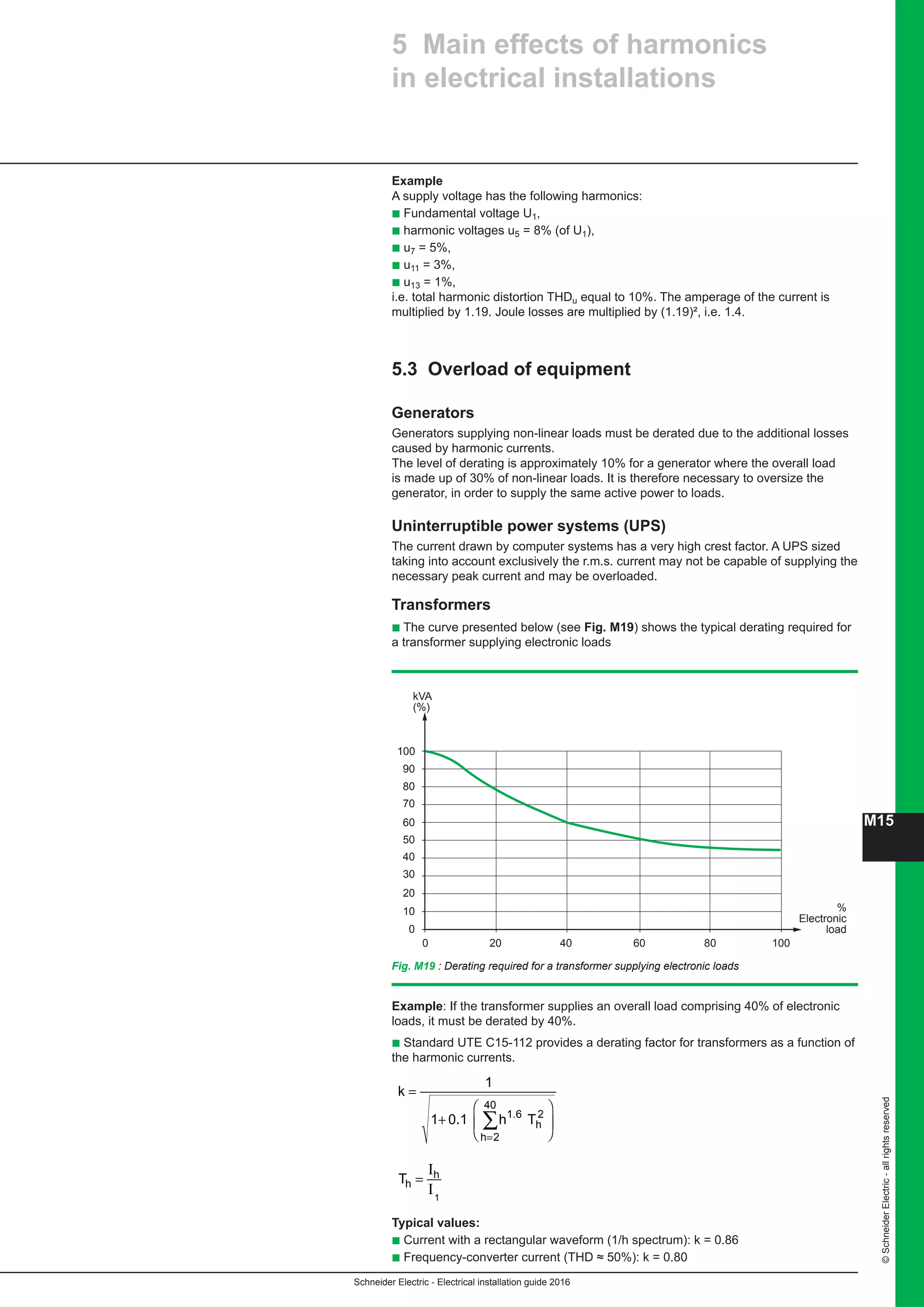
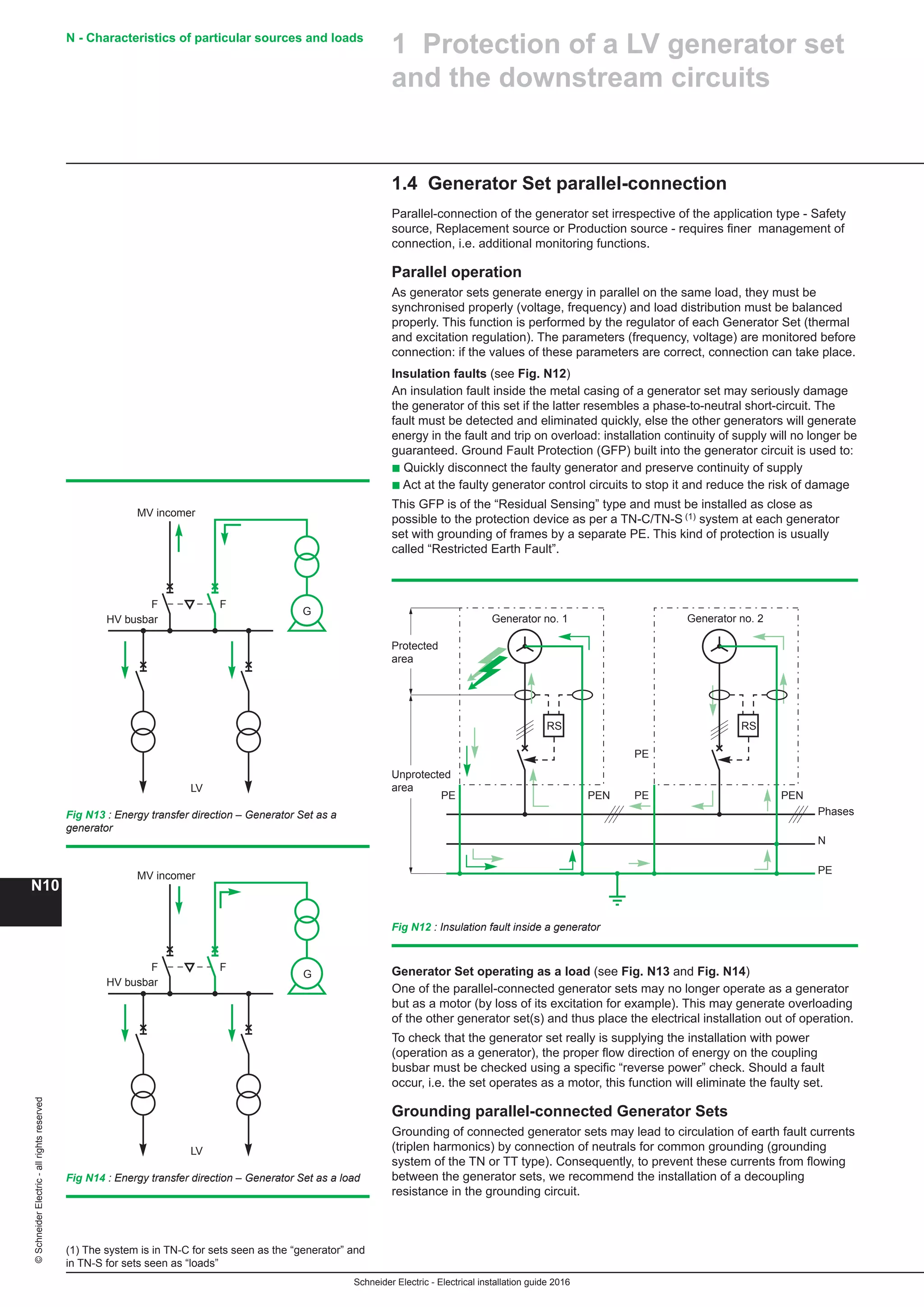
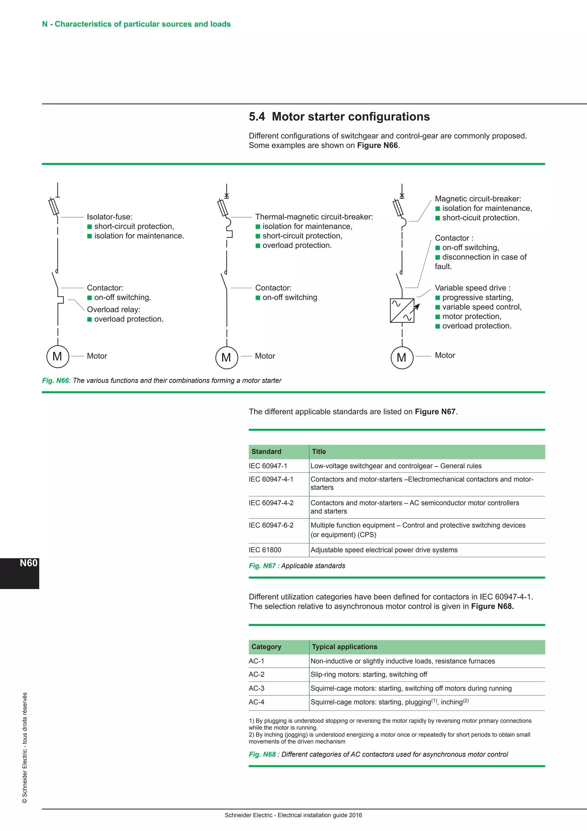
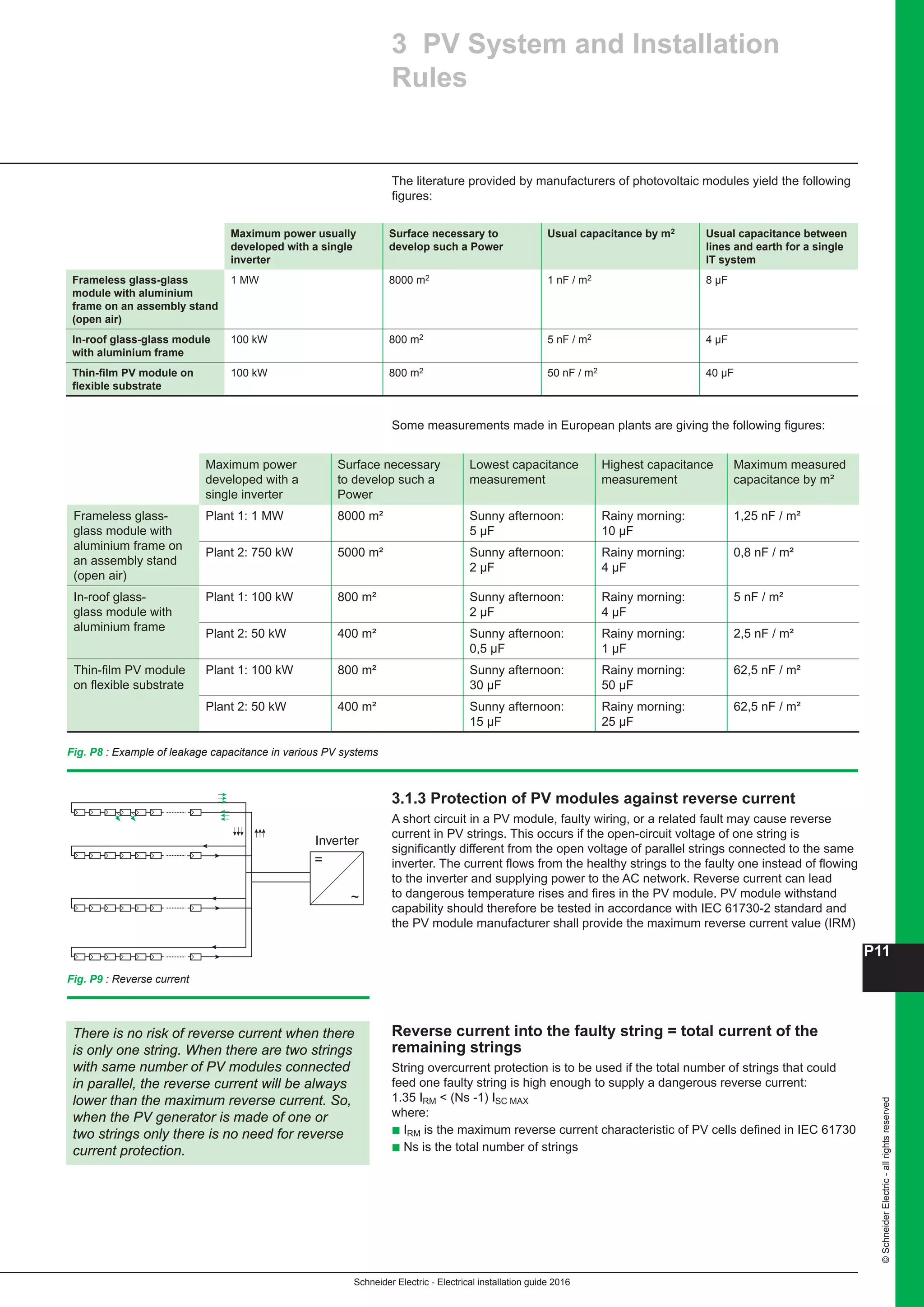
8.3.3 Pole mounted substation
Application
These substations are mainly used for the supply of isolated rural consumers
from MV overhead lines.
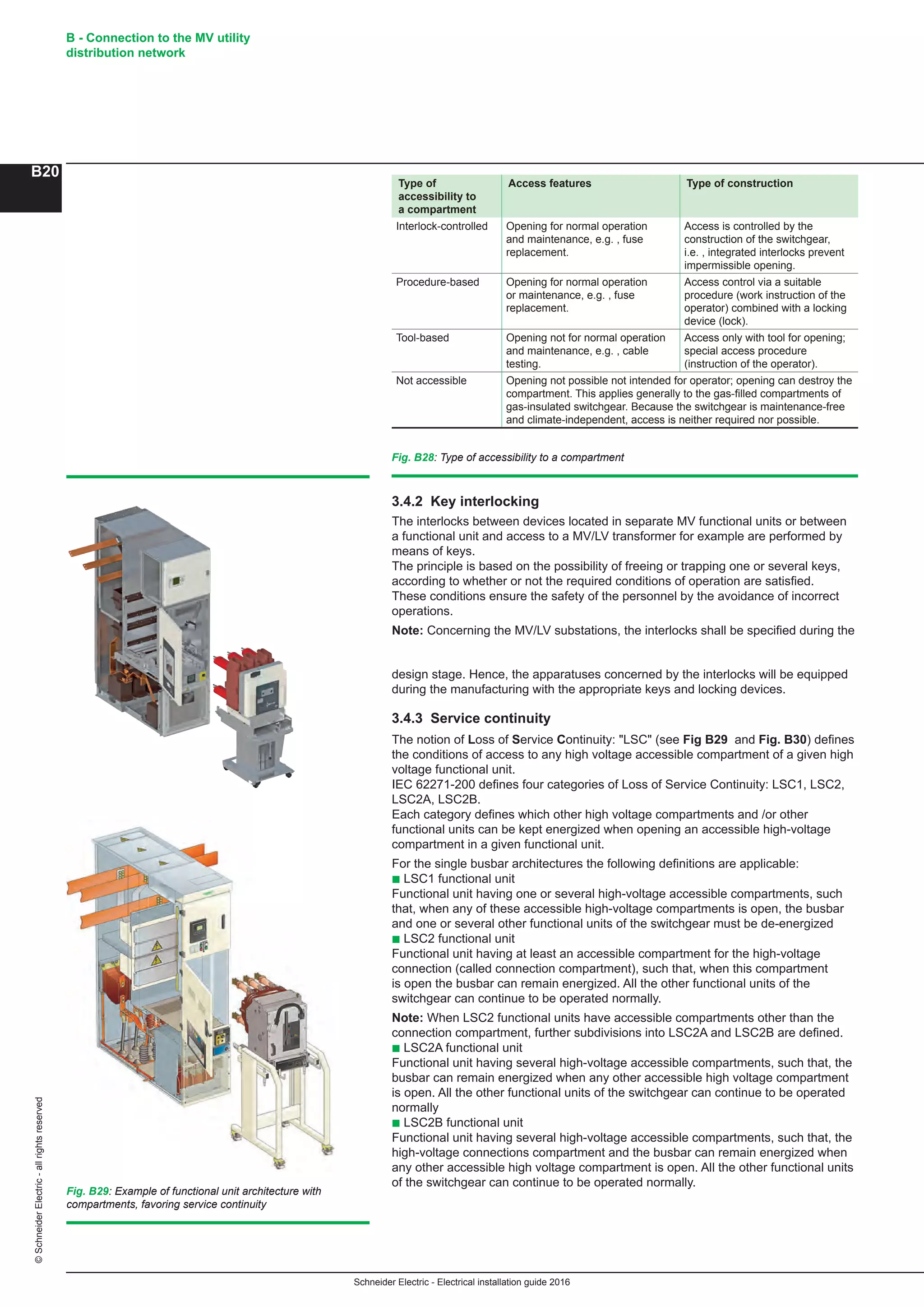
Constitution
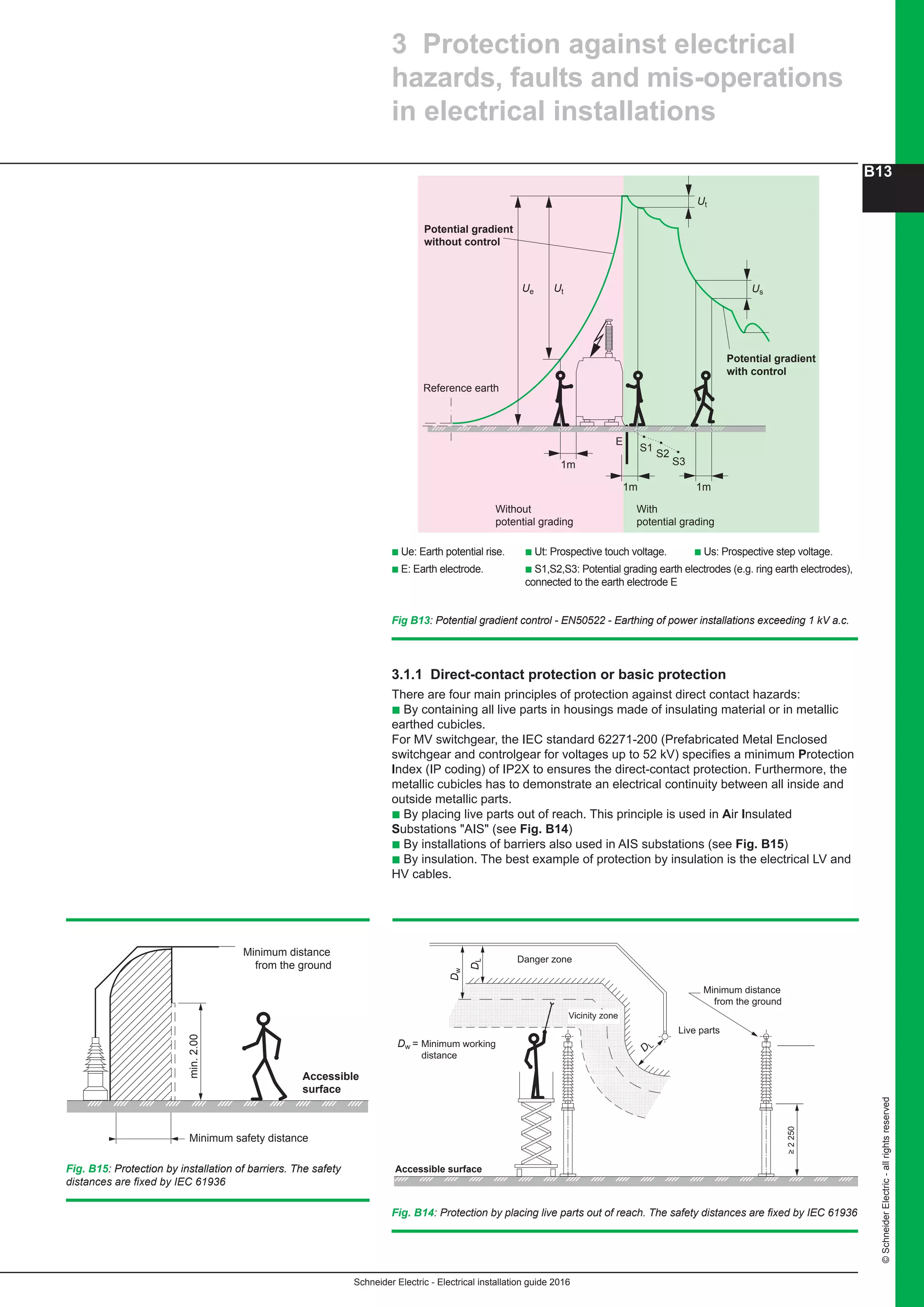
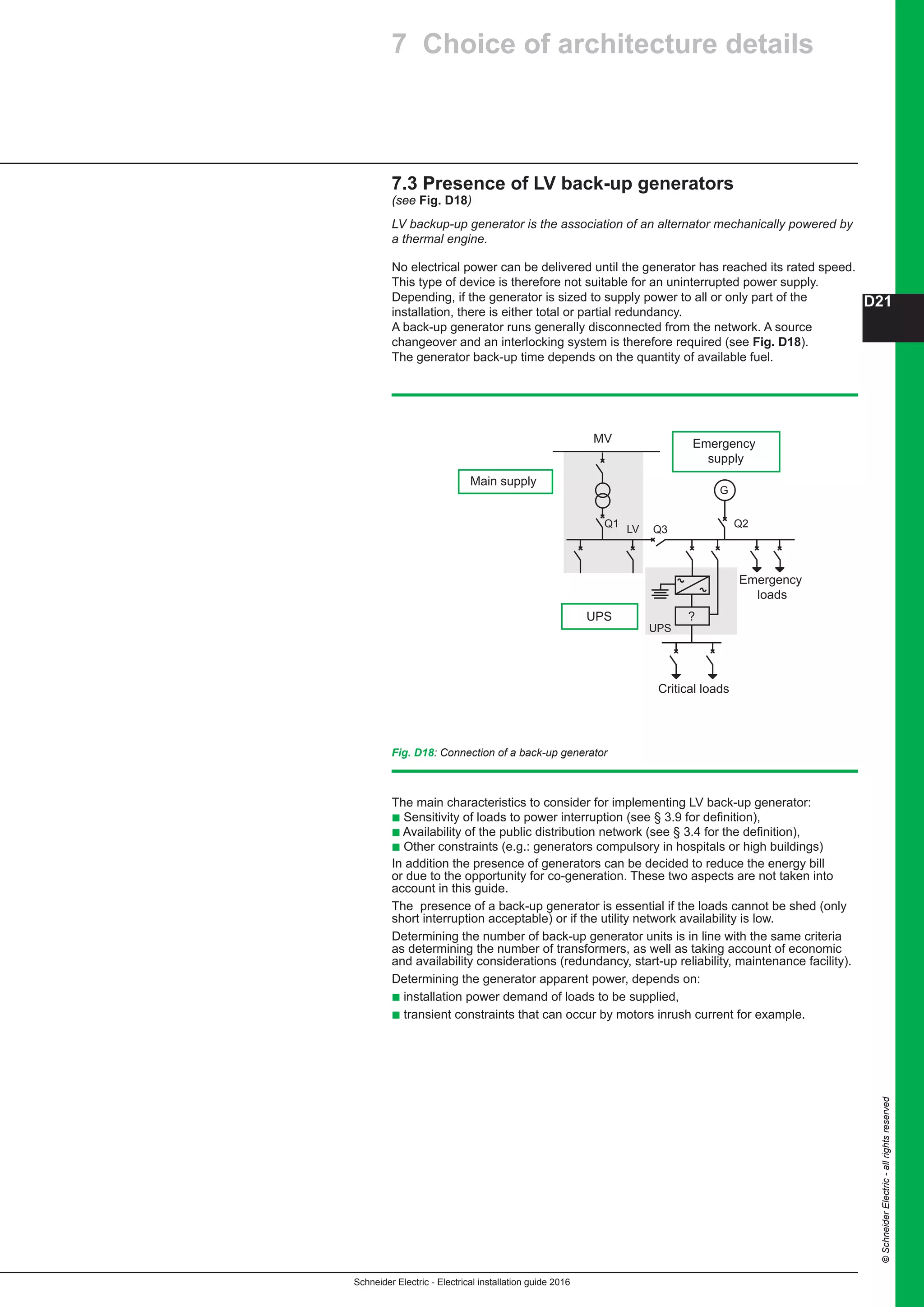
This type of substation includes (see Fig. B60):
b A single pole mounted MV/LV power transformer that is, according to the local
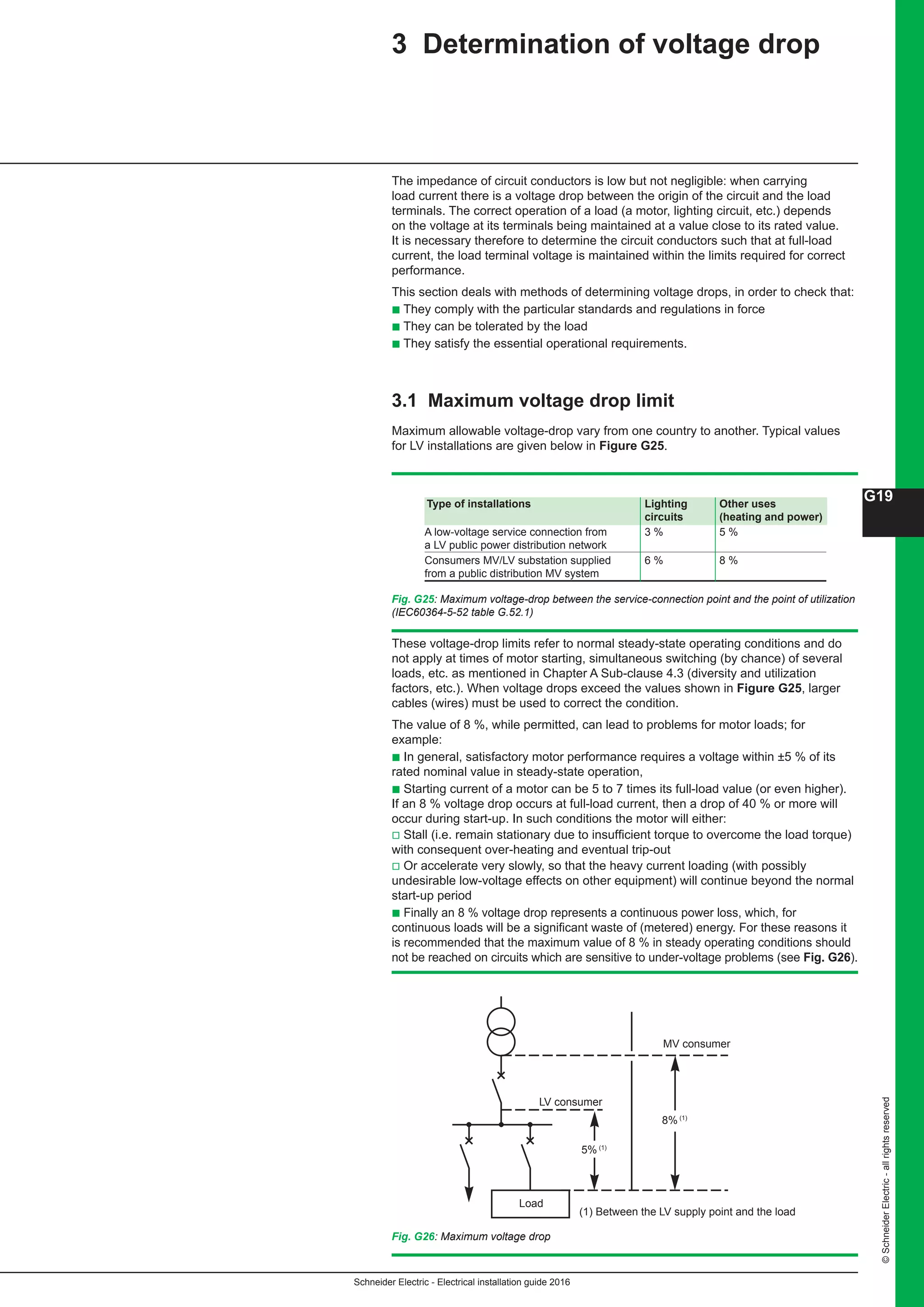
rules associated or not with:
v A load break switch
v A set of three fuses
v A set of three surge arrestors
b A low voltage circuit breaker
b An earthing electrode realized at the bottom of the pole supporting the equipment.
The location of the substation must allow easy access of the personnel and handling
equipment.
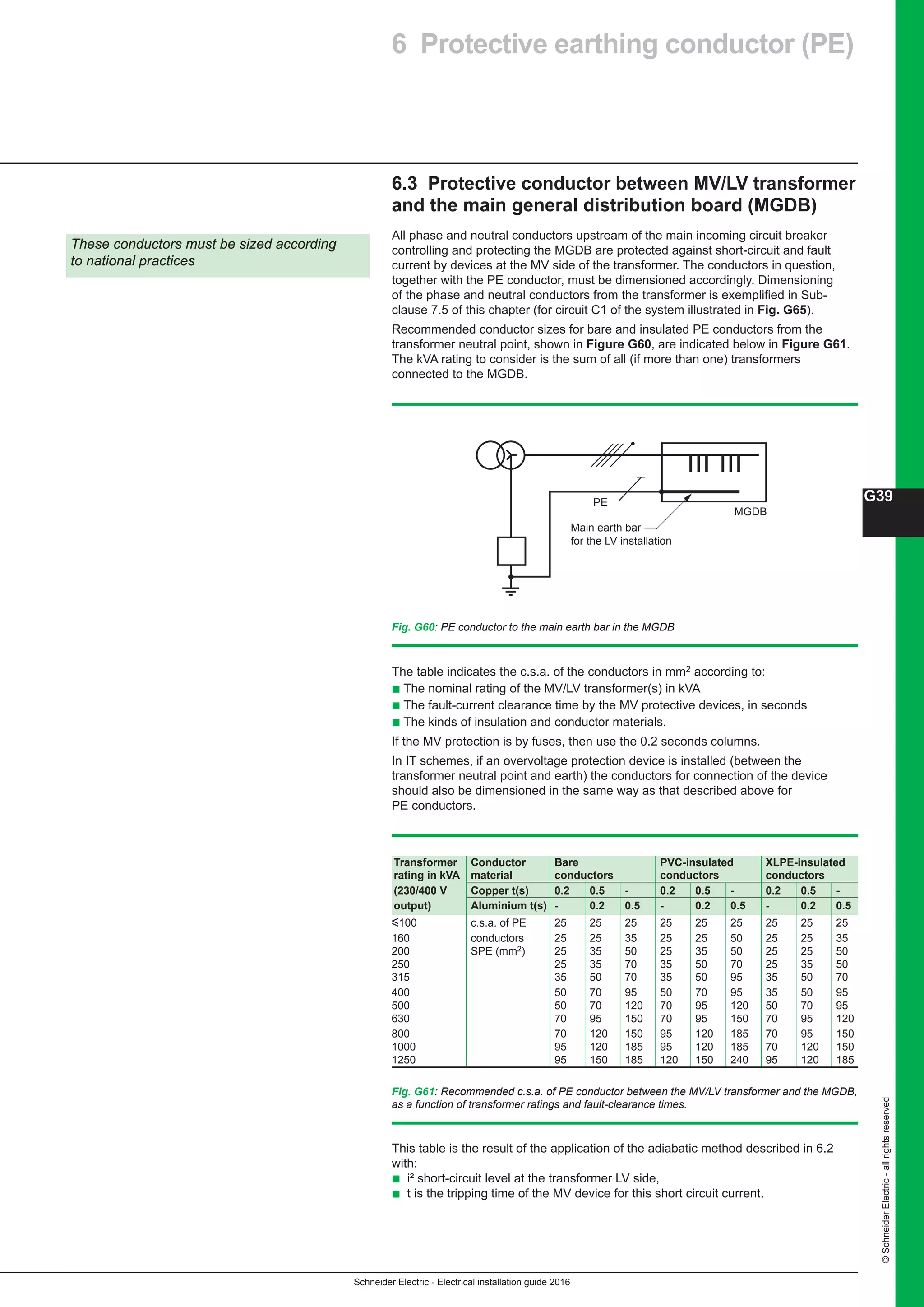
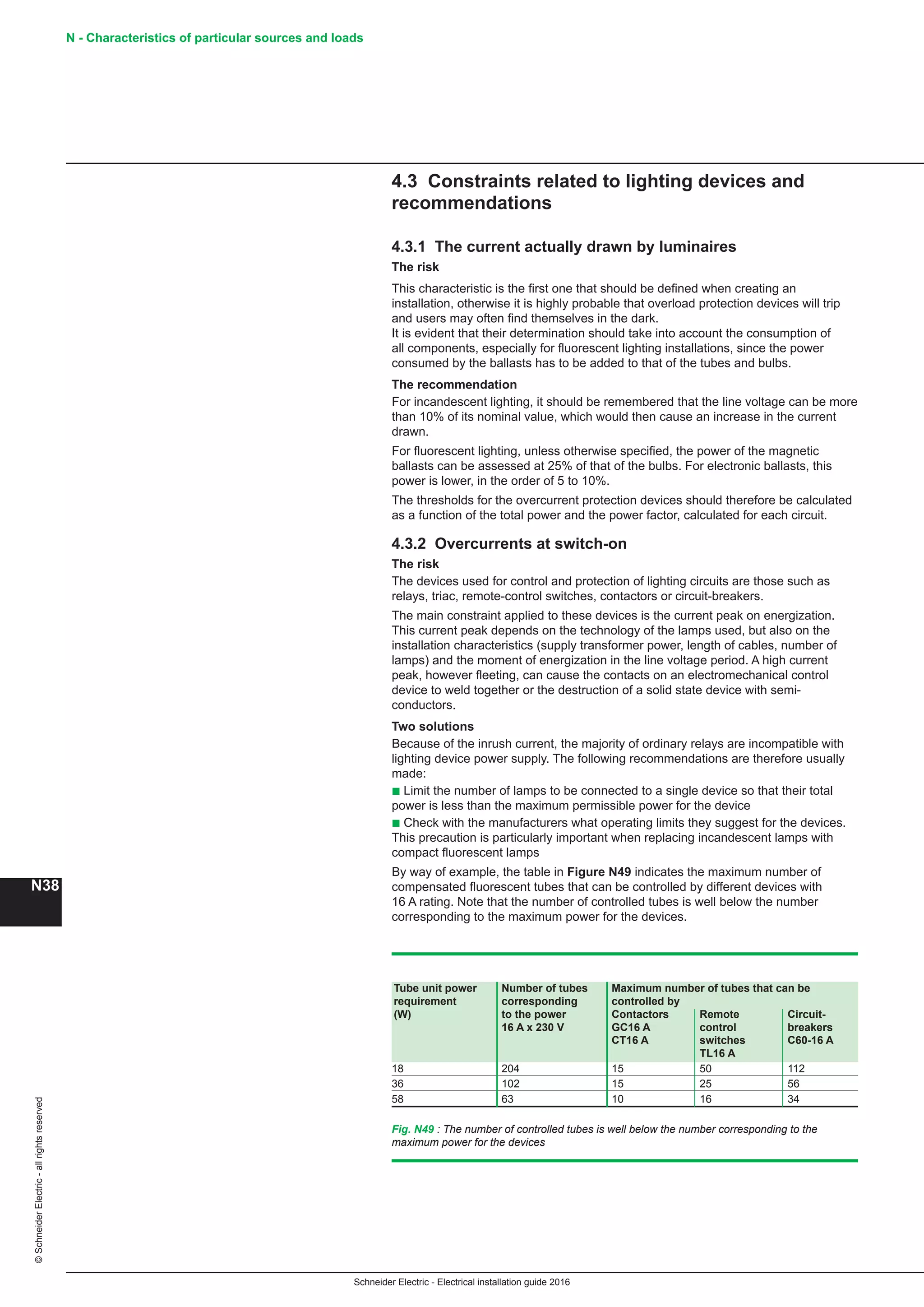
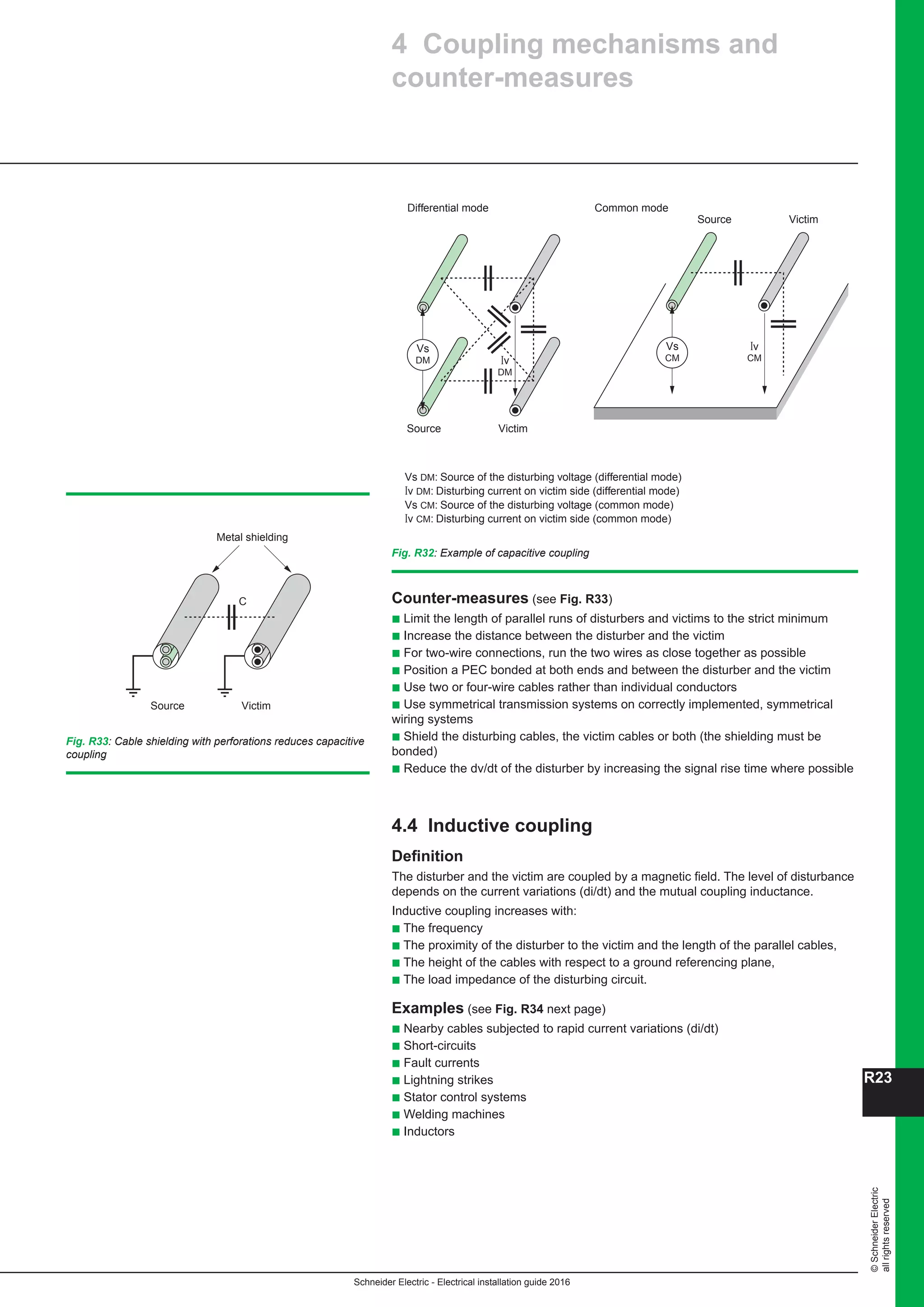
8 Types and constitution
of MV/LV distribution substations
Ground level
Half buried
Underground
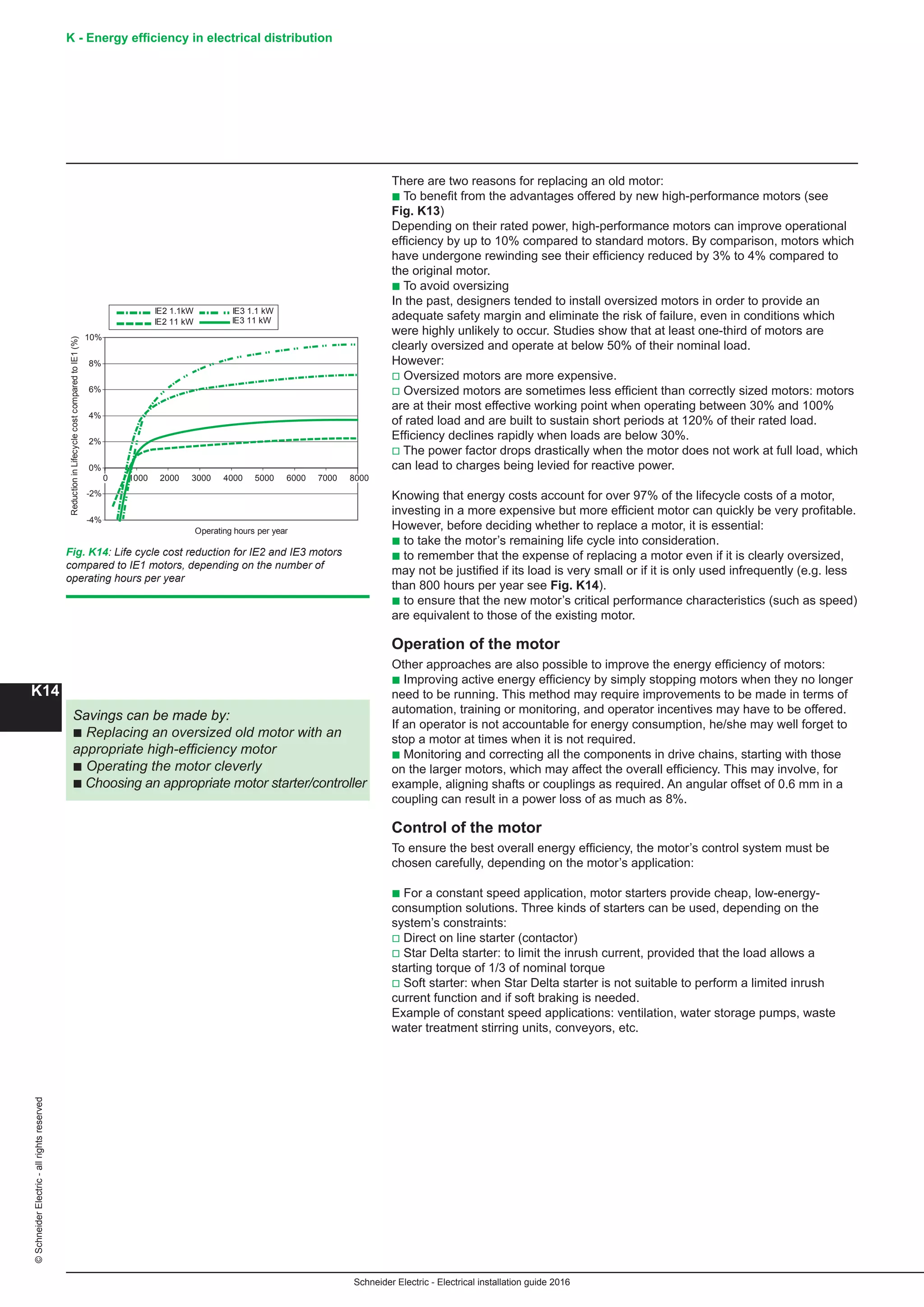
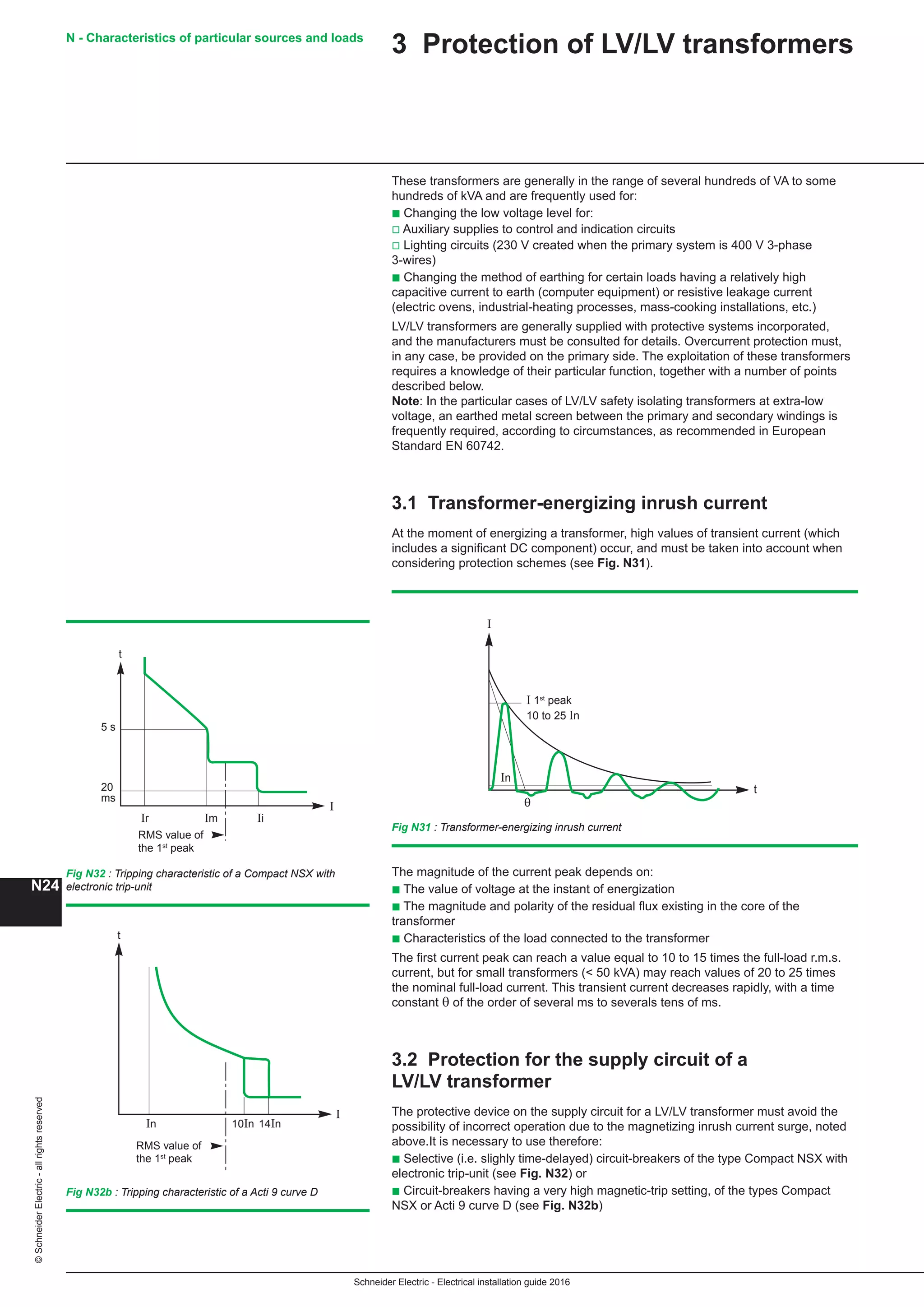
Fig. B57: Outdoor substations. The three type of design
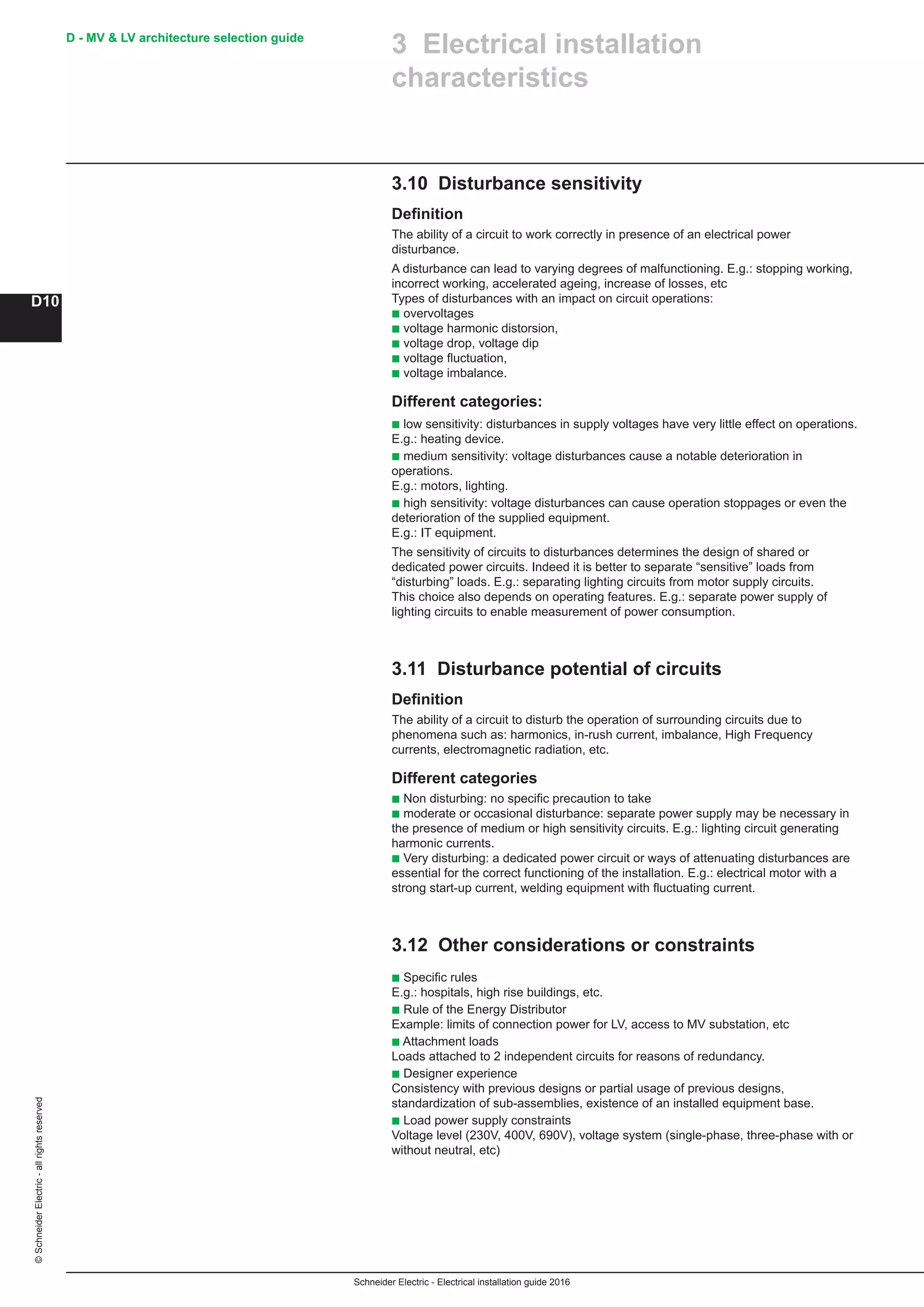
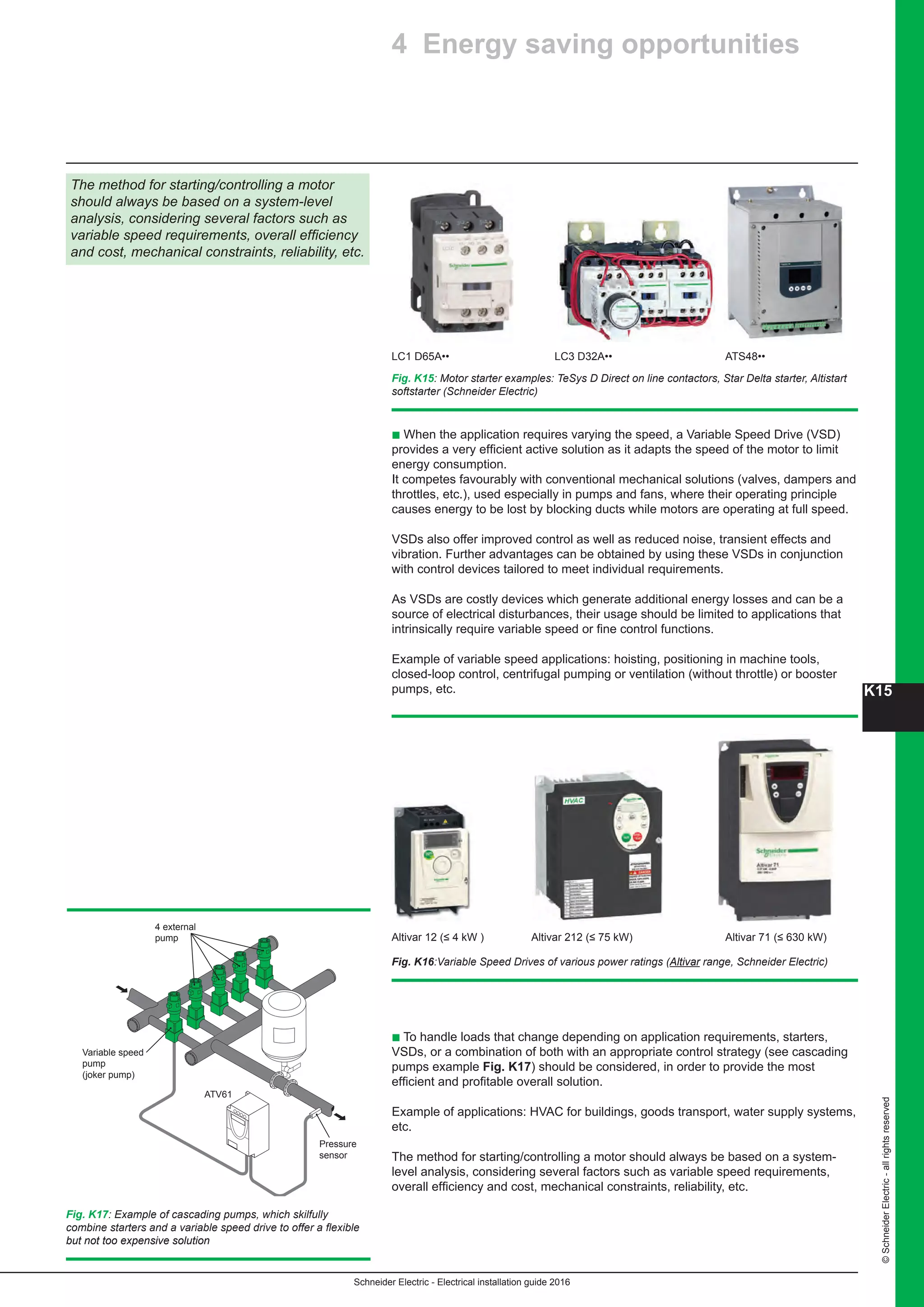
Fig. B60: Pole mounted MV/LV substation
Earthing conductor 25 mm² copper
Protective conductor cover
LV circuit breaker D1
Safety earth mat
Lightning
arresters
Fuse
a - b -
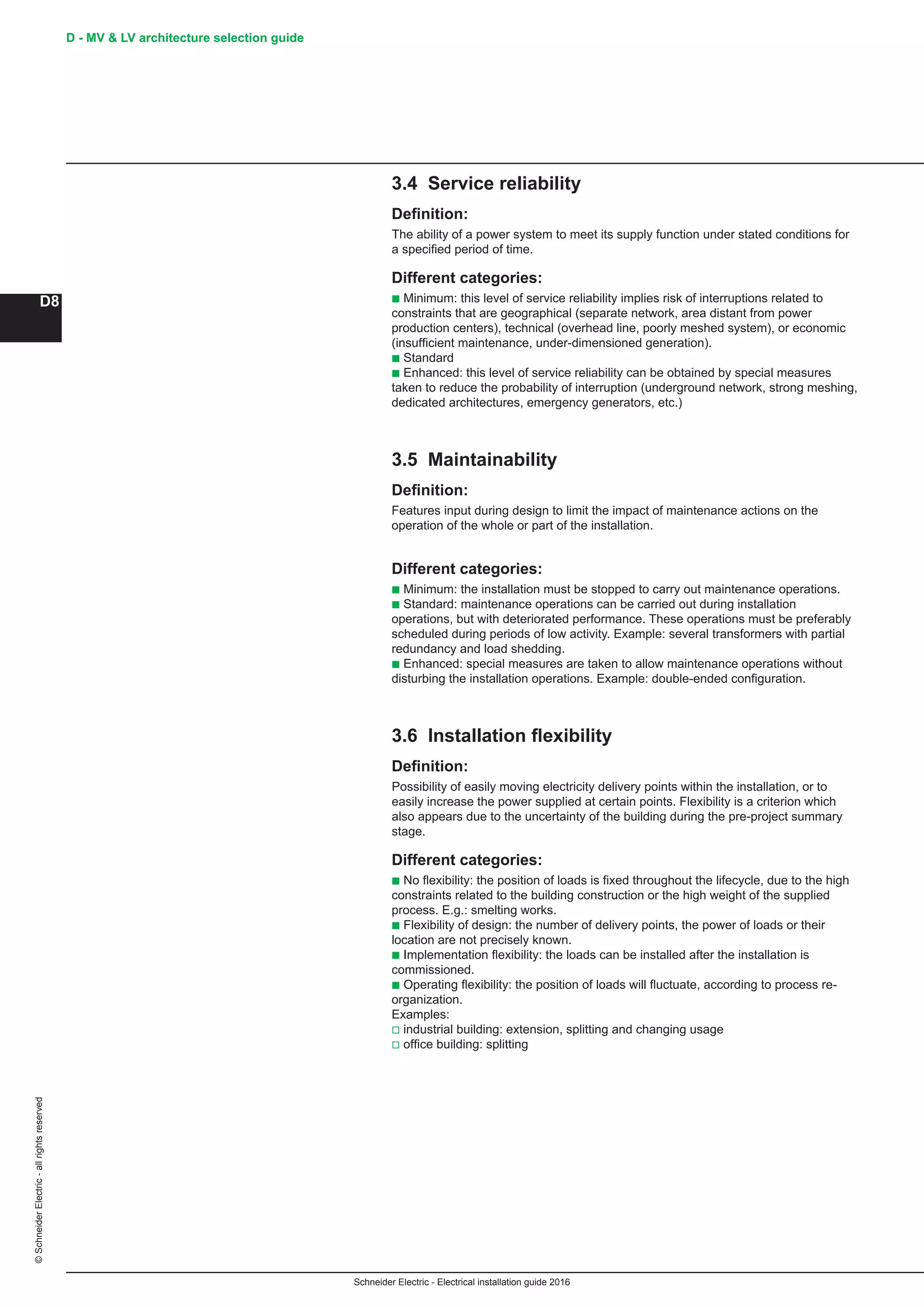
Fig. B58: Outdoor substations [a] Ground level walk in type
substation; [b] Half buried non walk in type substation
Fig. B59: Outdoor substation without enclosure](https://image.slidesharecdn.com/10electrical-installation-guide-2016-160721063350/75/10-electrical-installation-guide-2016-79-2048.jpg)


![Schneider Electric - Electrical installation guide 2016
©SchneiderElectric-allrightsreserved
E15
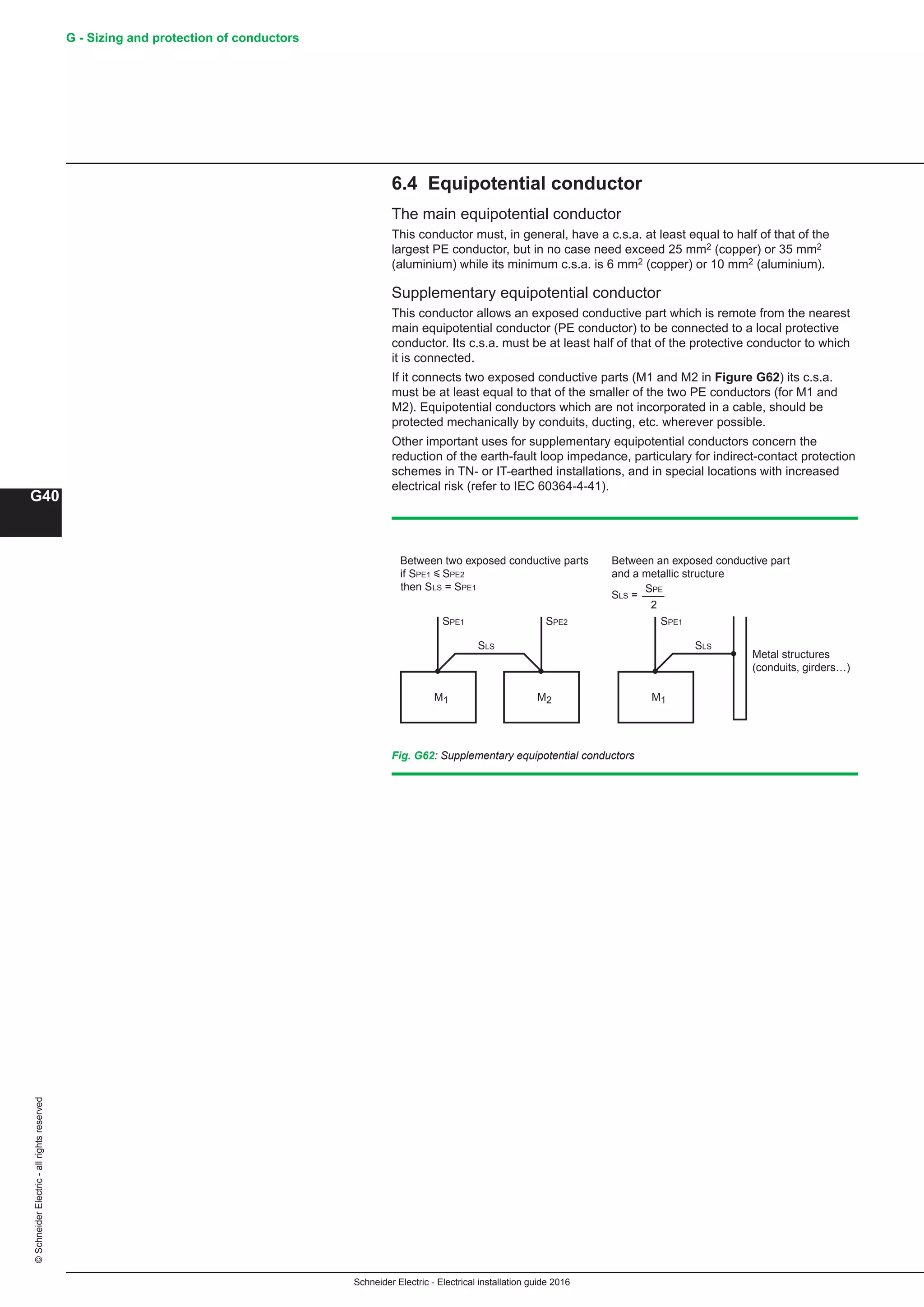
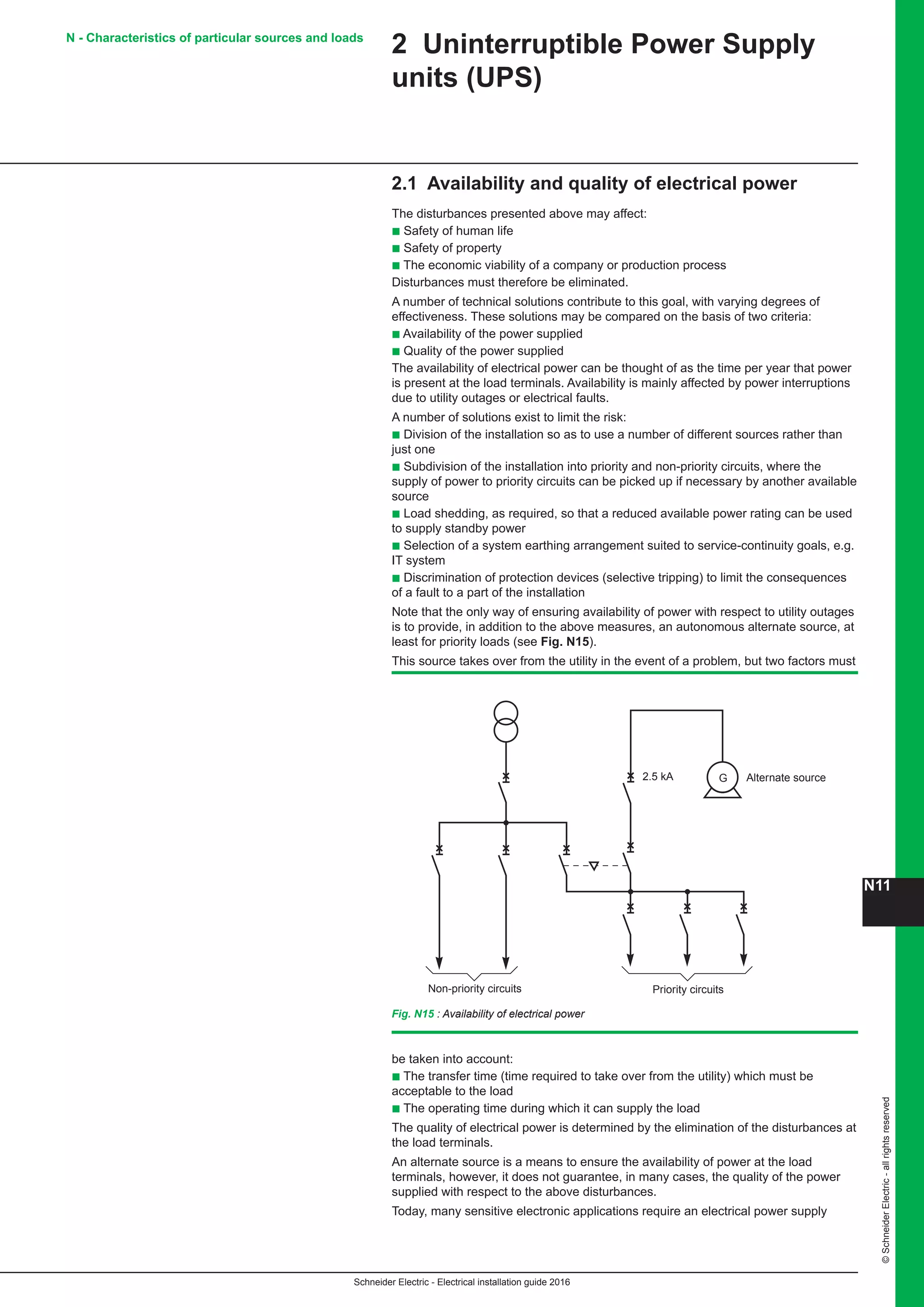
E - Distribution in low-voltage installations
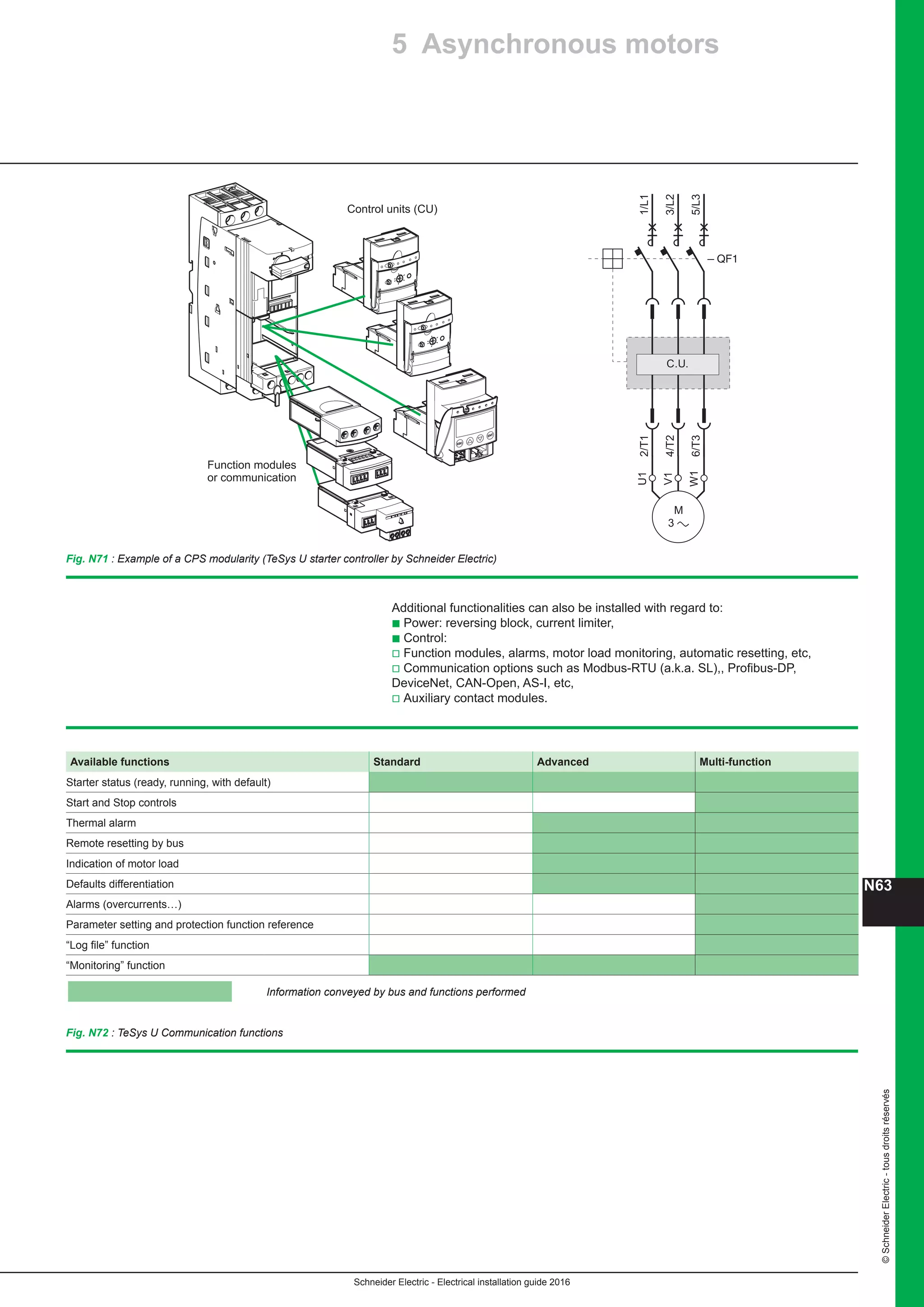
2 The installation system
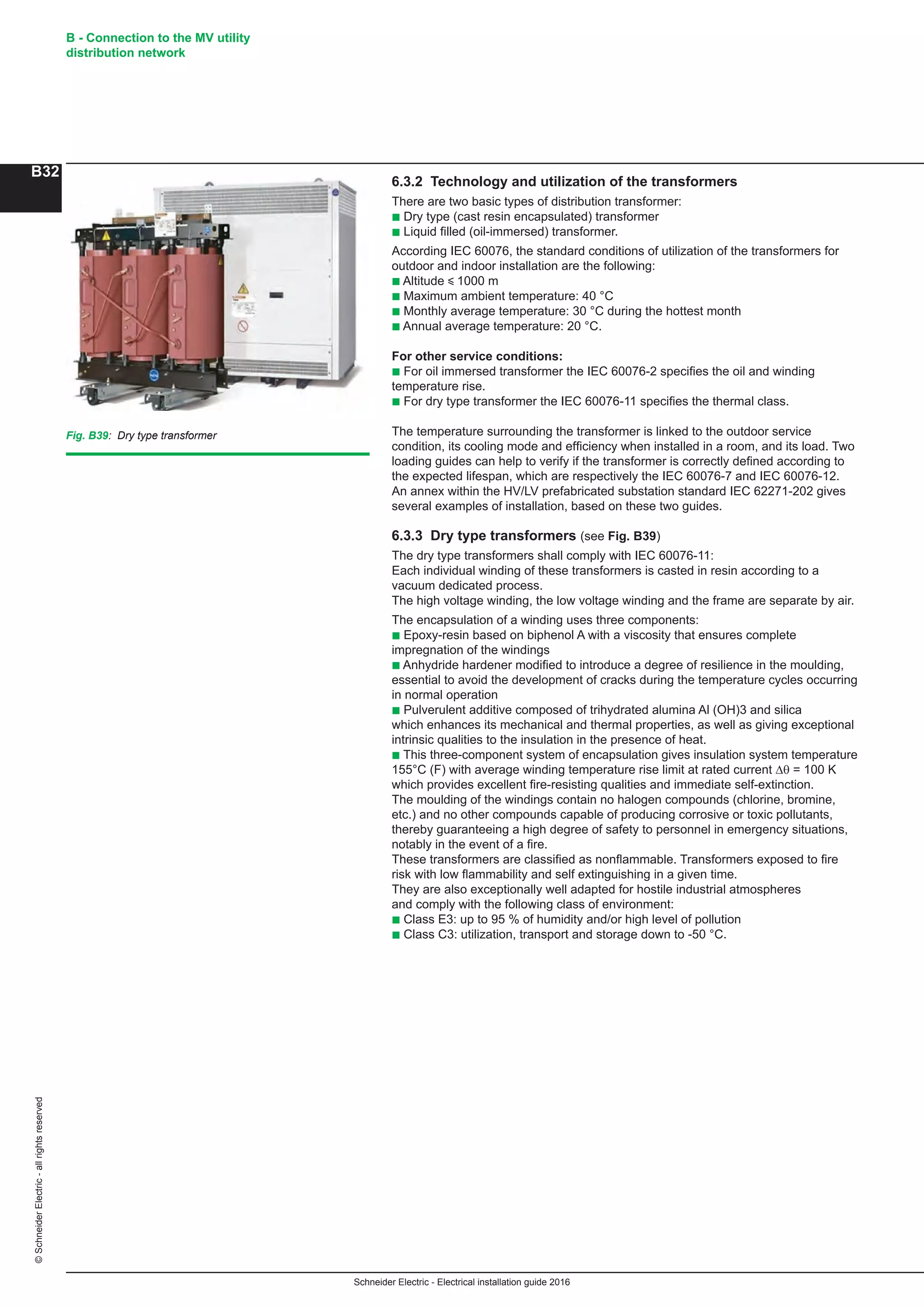
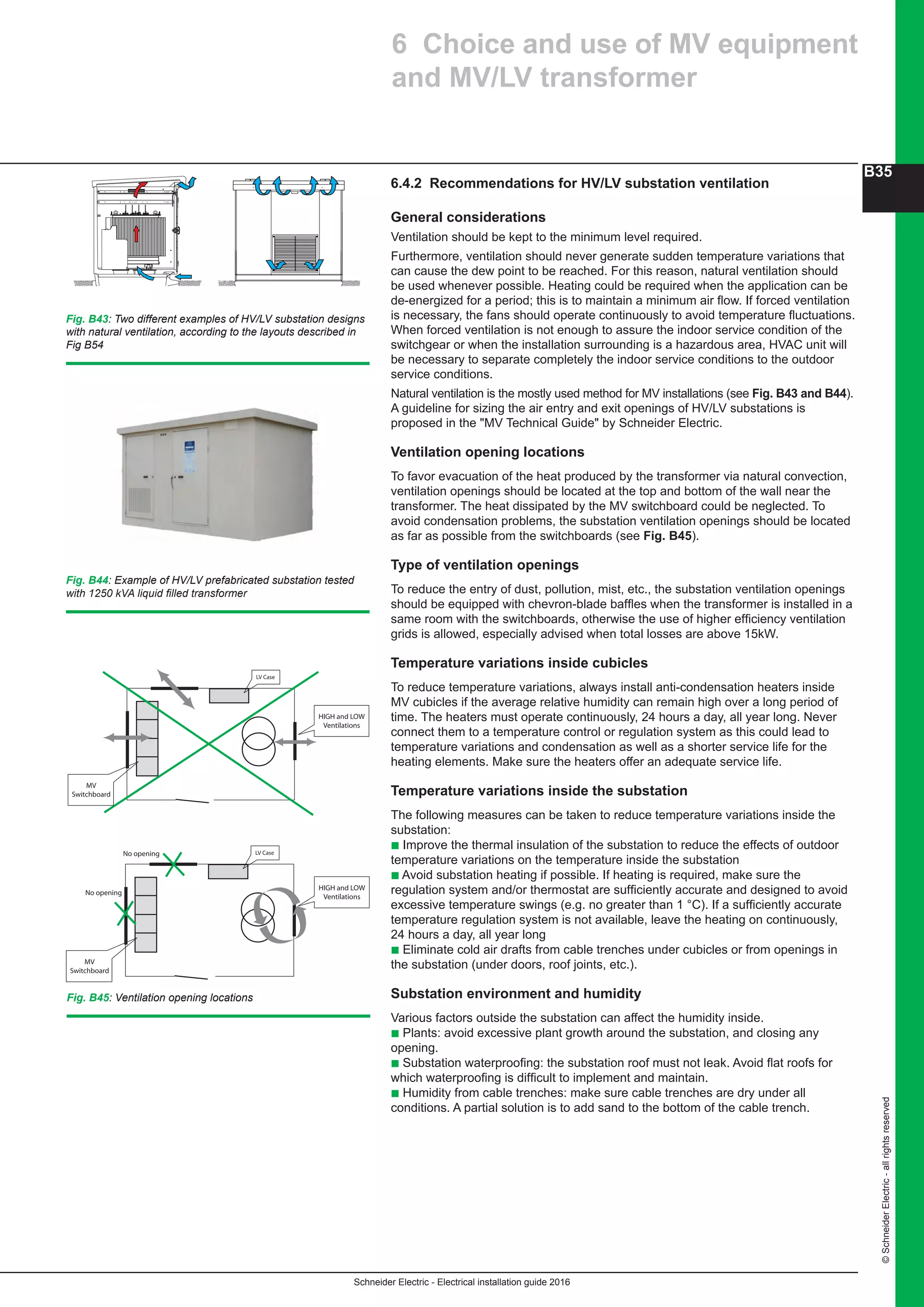
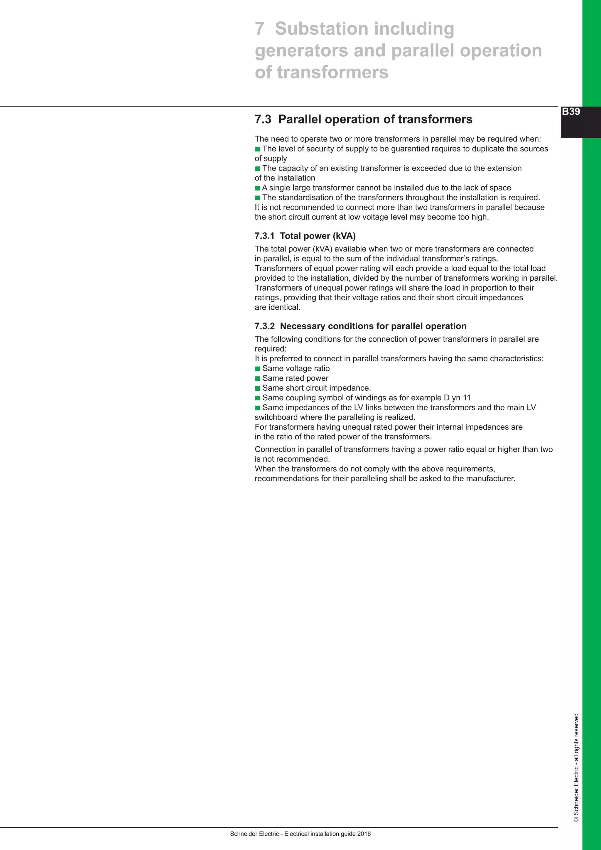
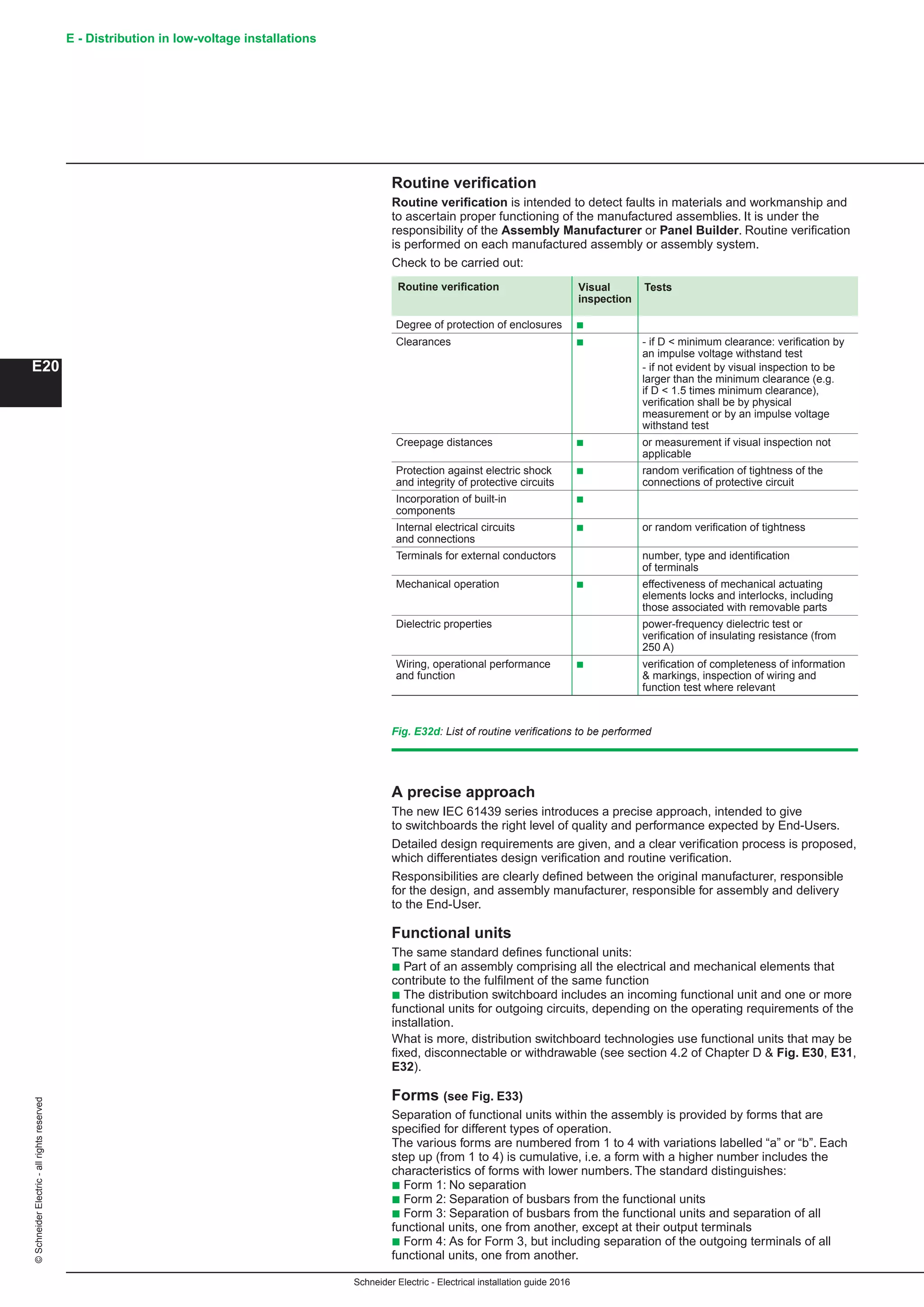
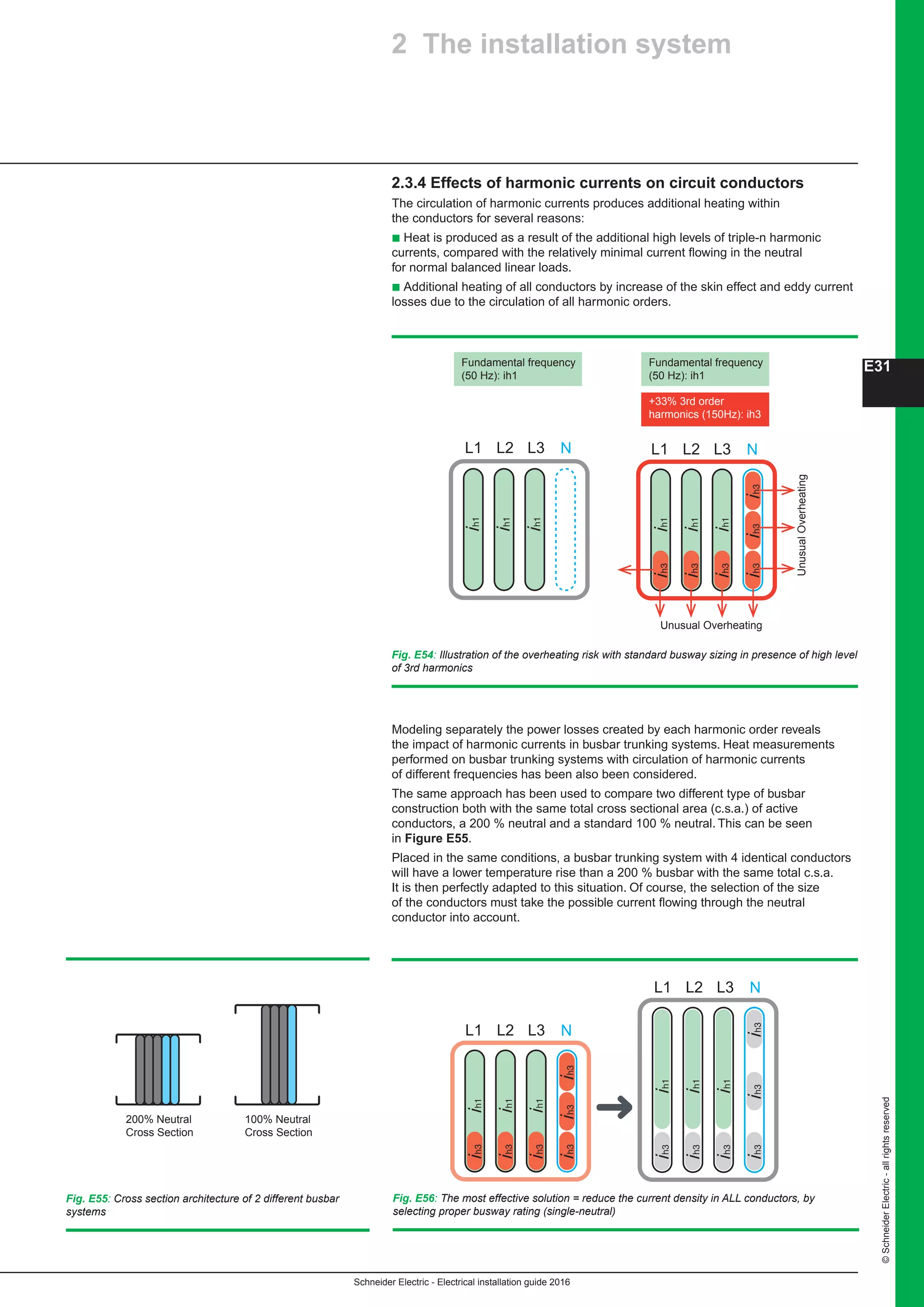
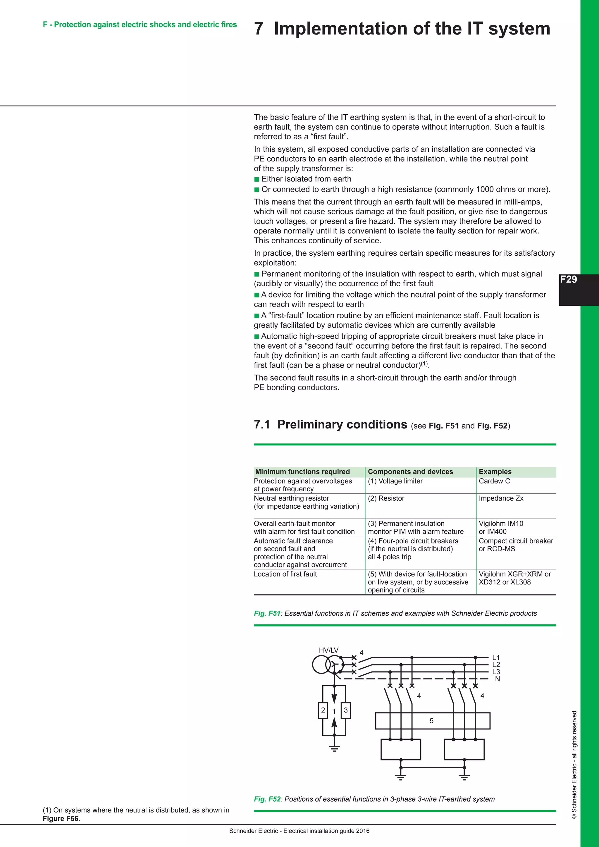
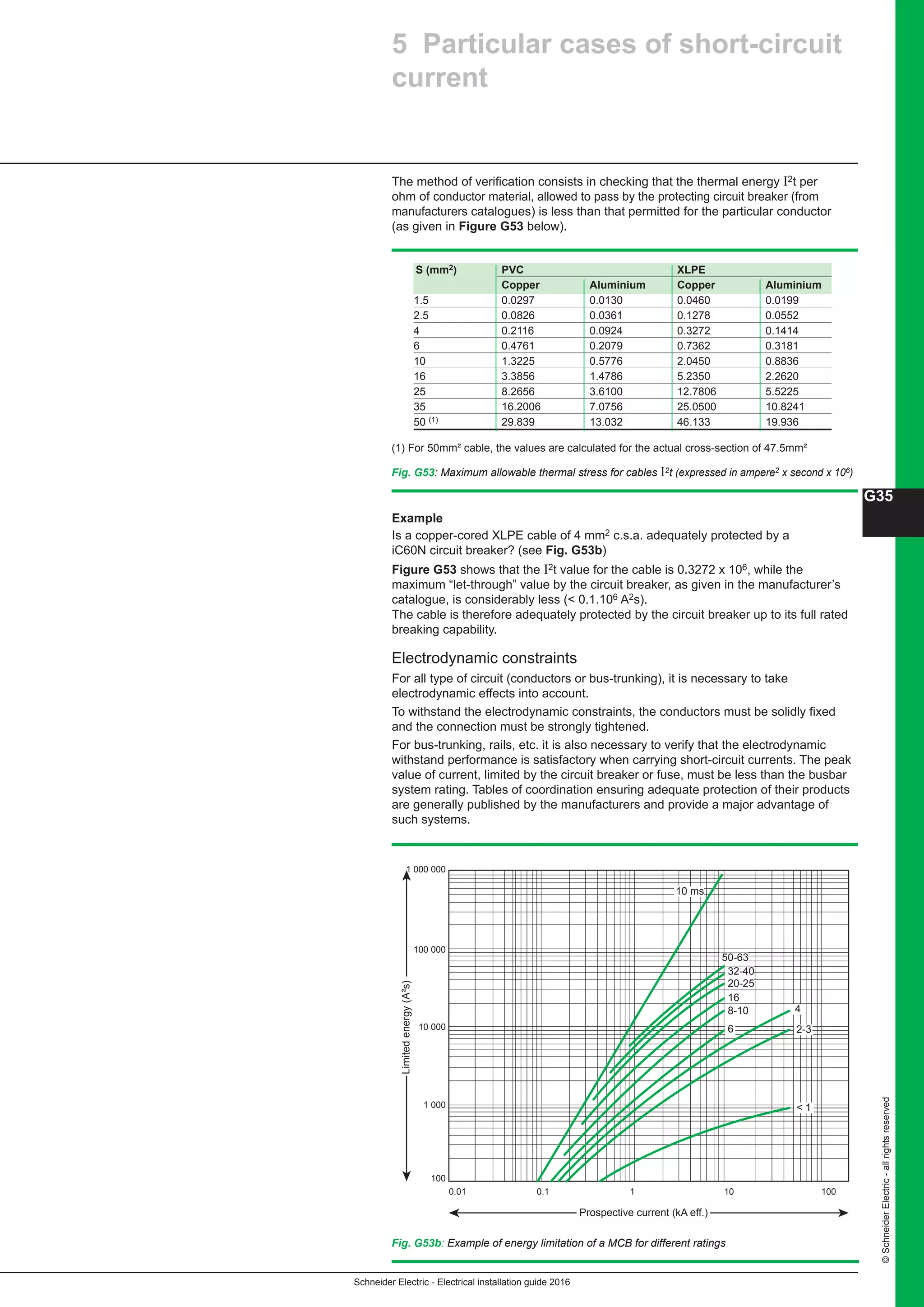
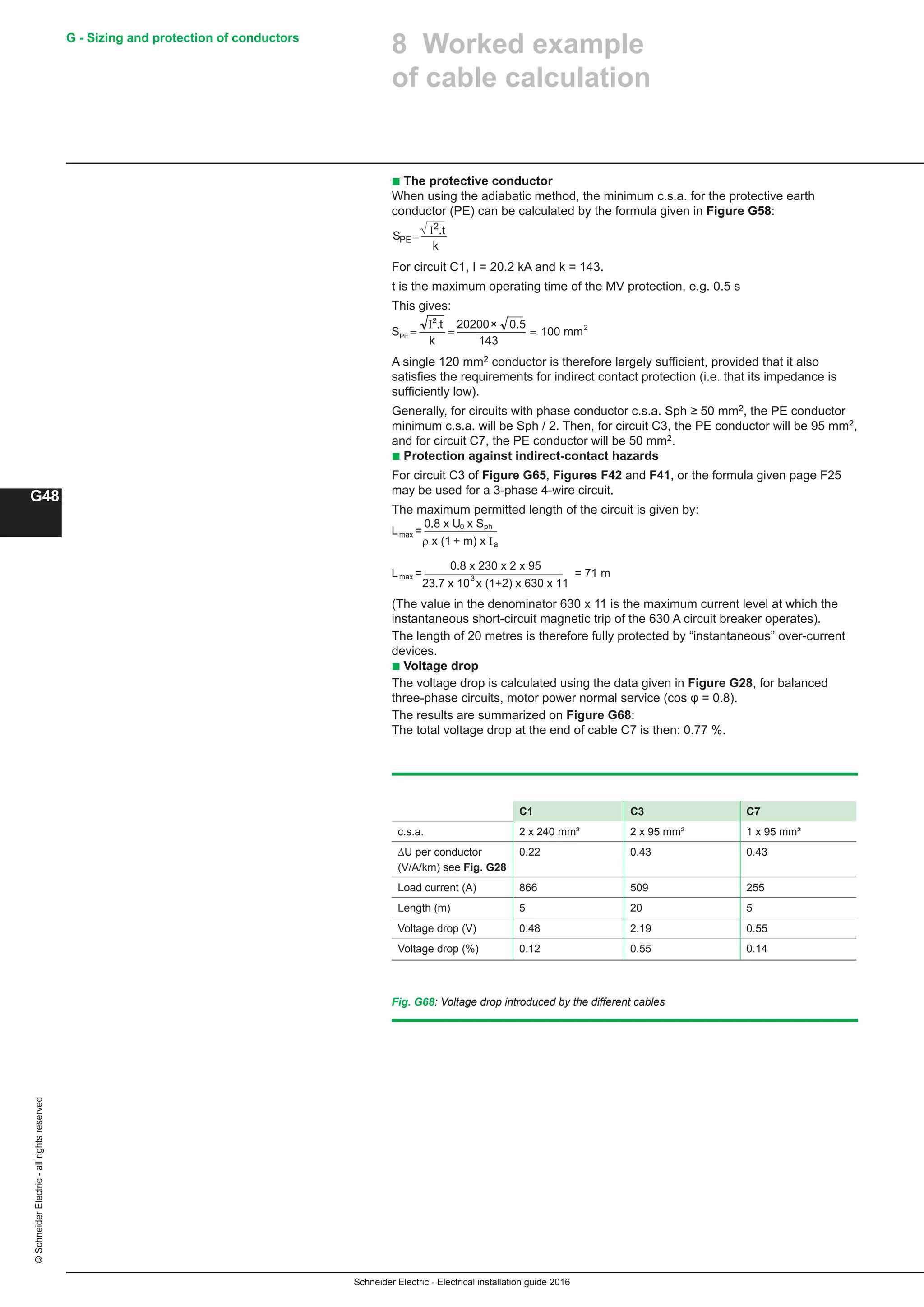
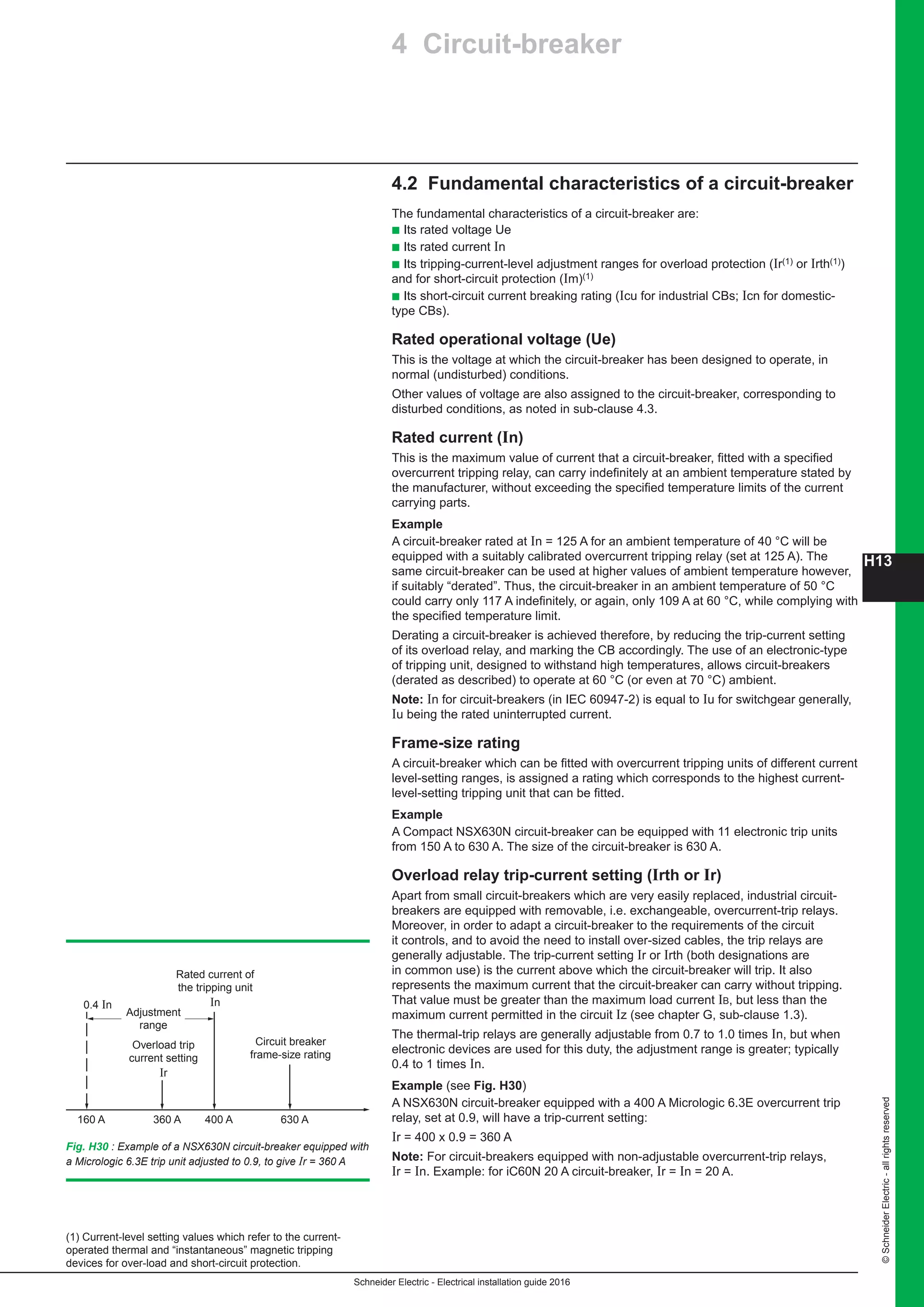
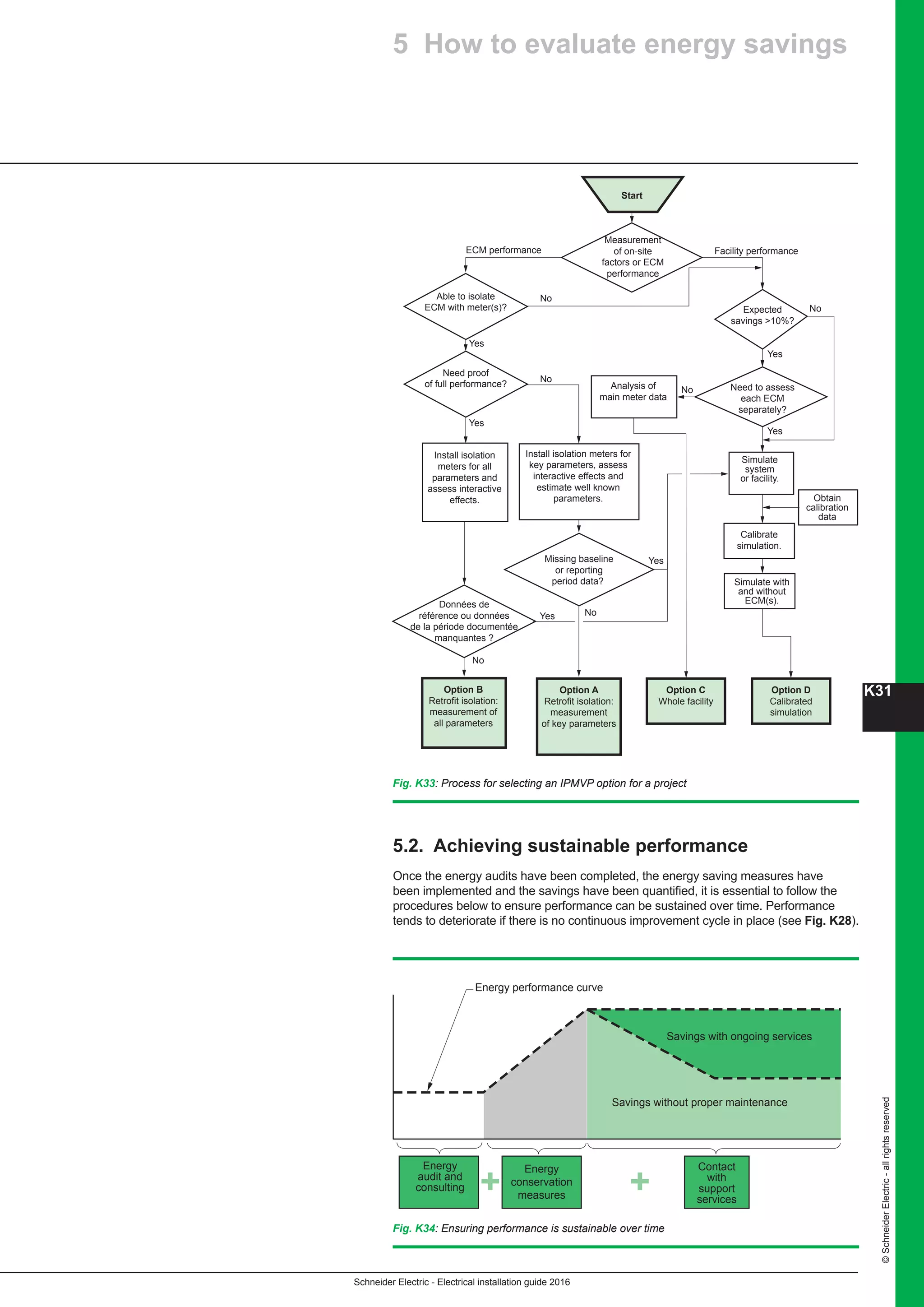
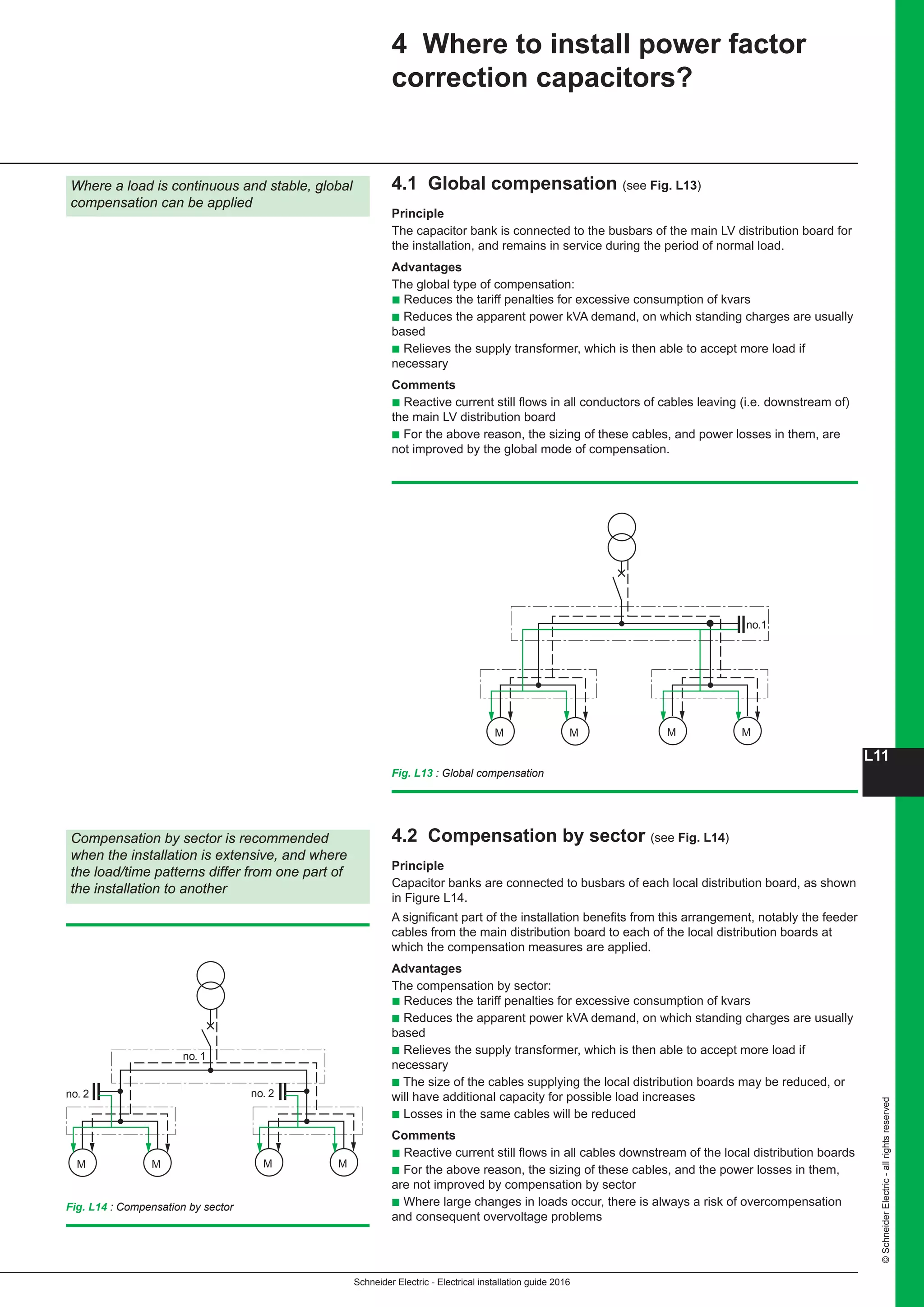
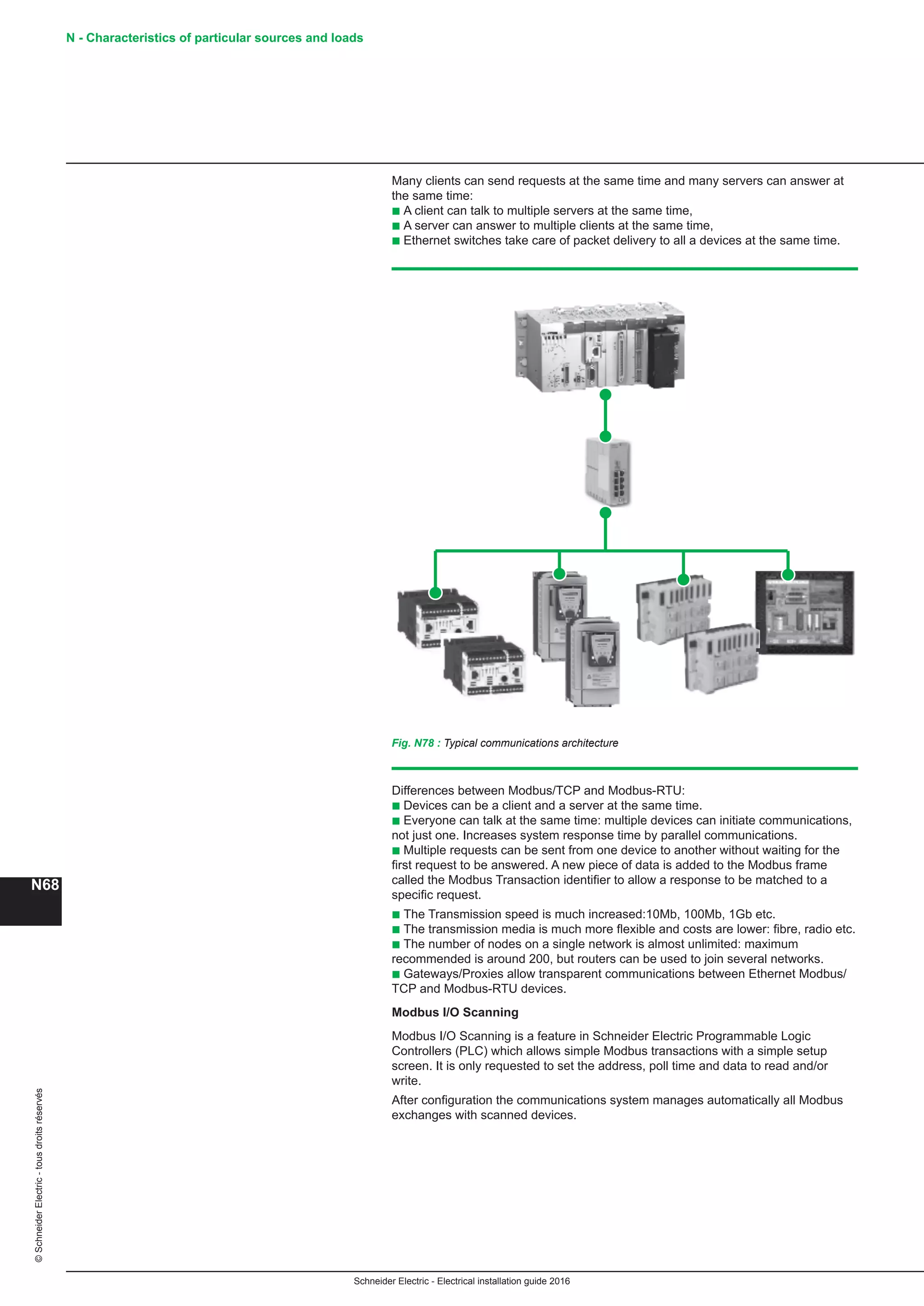
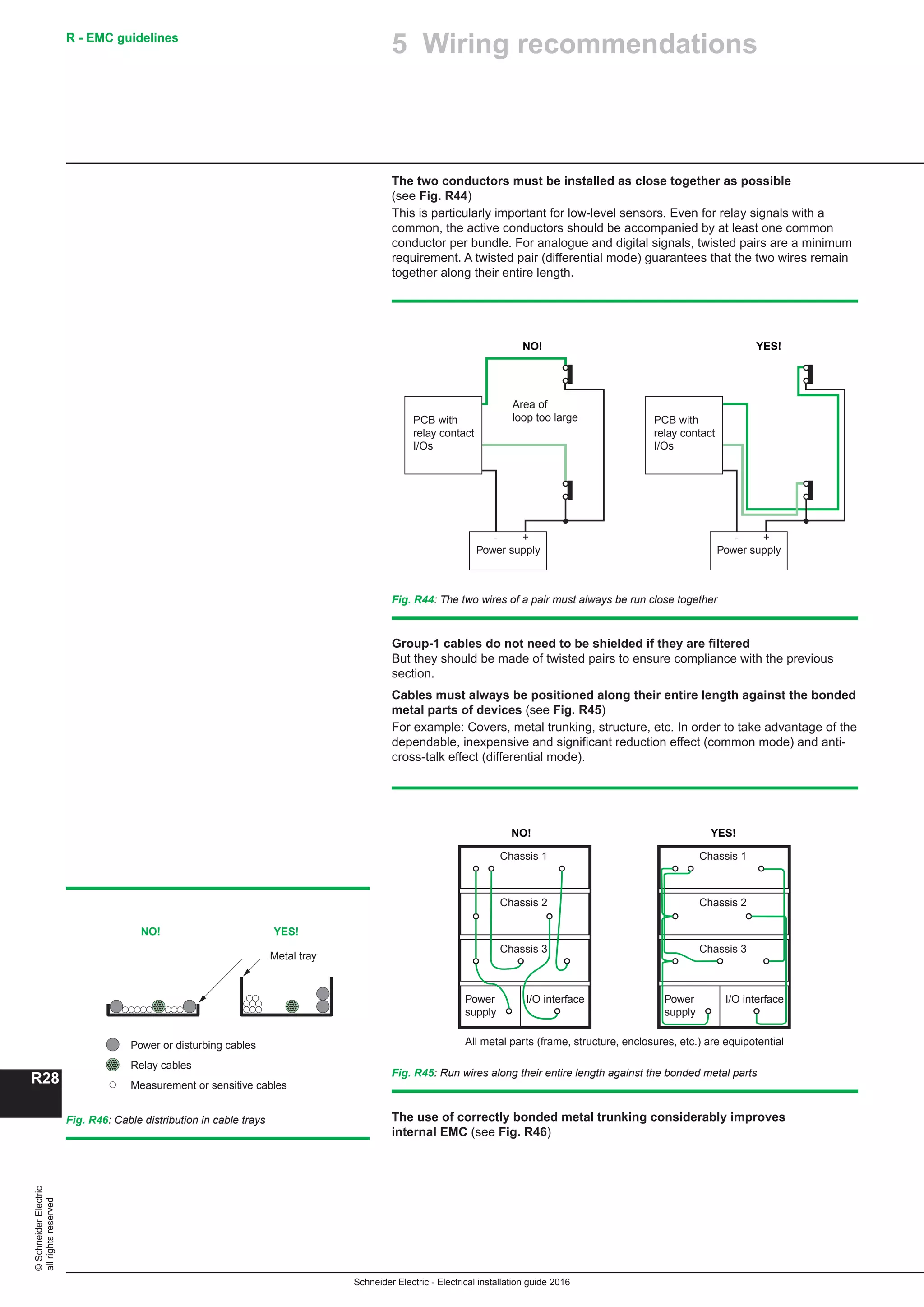
2.1 Distribution switchboards
A distribution switchboard is the point at which an incoming-power supply divides
into separate circuits, each of which is controlled and protected by the fuses
or switchgear of the switchboard. A distribution switchboard is divided into a number
of functional units, each comprising all the electrical and mechanical elements that
contribute to the fulfilment of a given function. It represents a key link in
the dependability chain.
Consequently, the type of distribution switchboard must be perfectly adapted to
its application. Its design and construction must comply with applicable standards
and working practises.
The distribution switchboard enclosure provides dual protection:
b Protection of switchgear, indicating instruments, relays, fusegear, etc. against
mechanical impacts, vibrations and other external influences likely to interfere with
operational integrity (EMI, dust, moisture, vermin, etc.)
b The protection of human life against the possibility of direct and indirect electric
shock (see degree of protection IP and the IK index in section 3.3 of Chapter E).
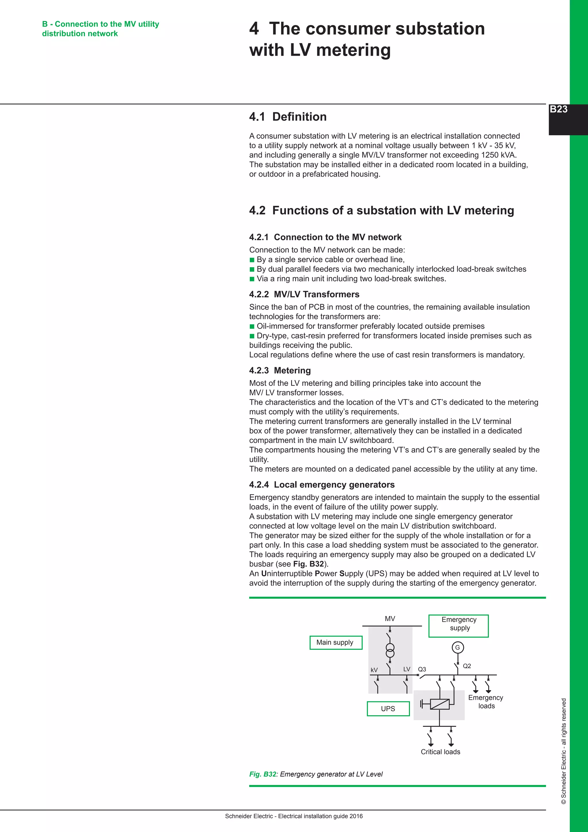
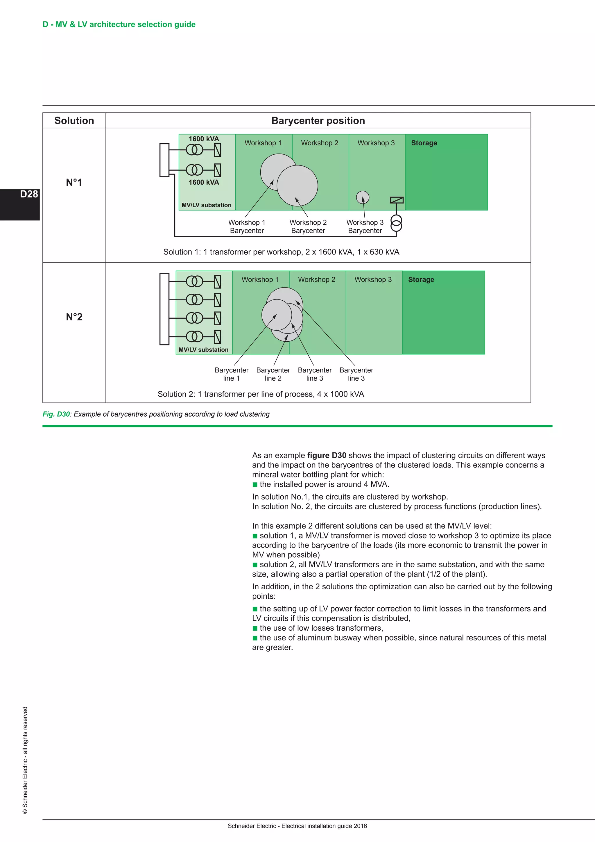
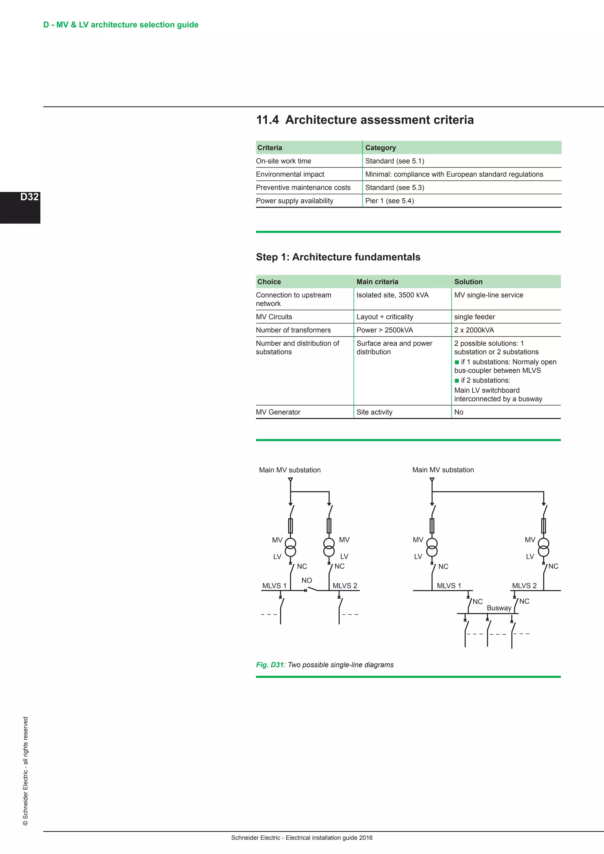
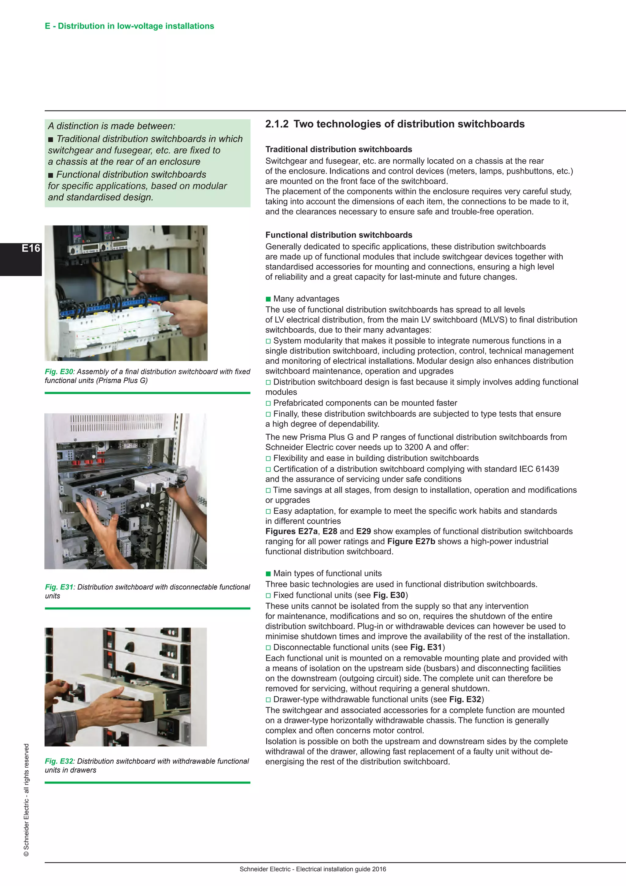
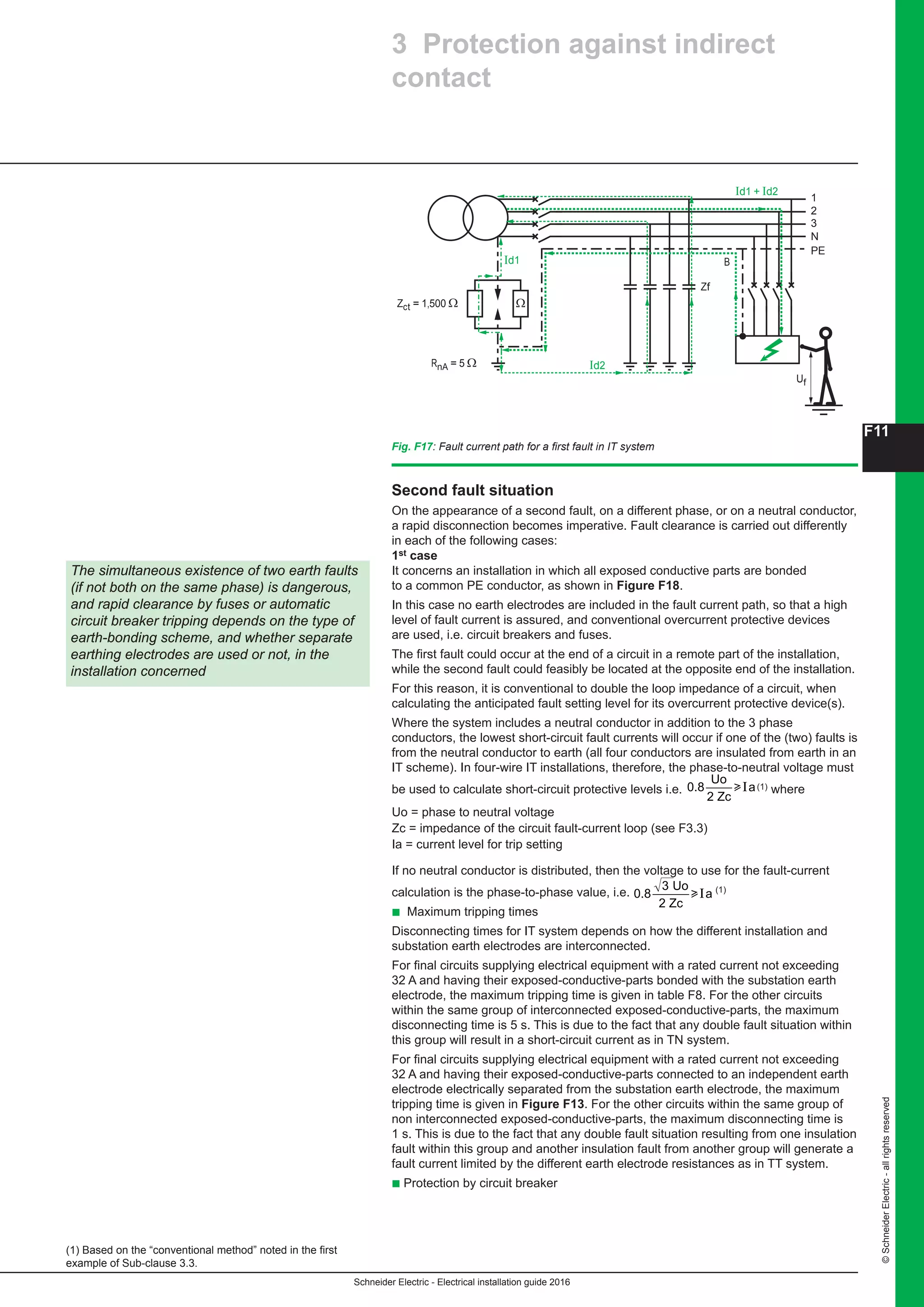
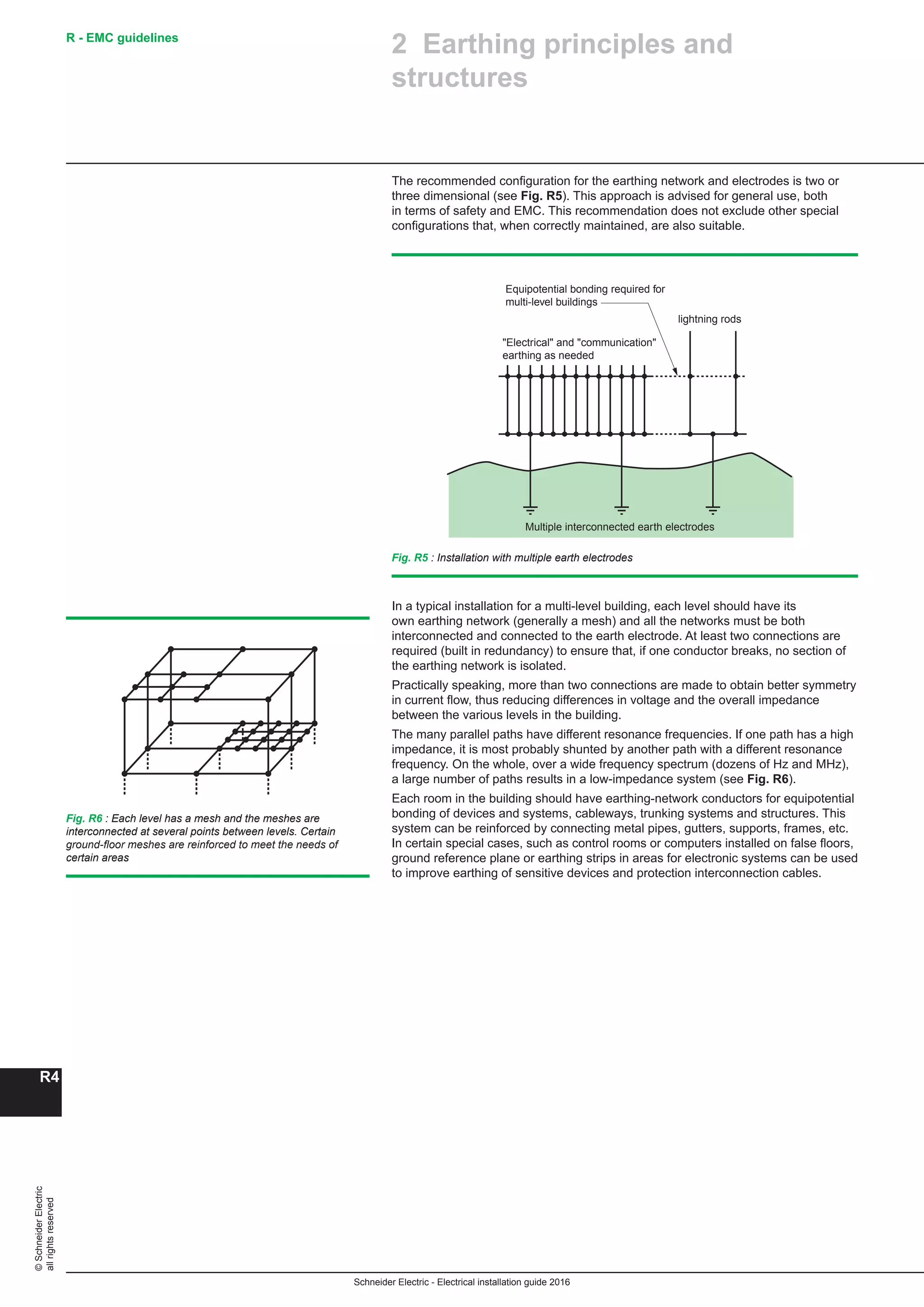
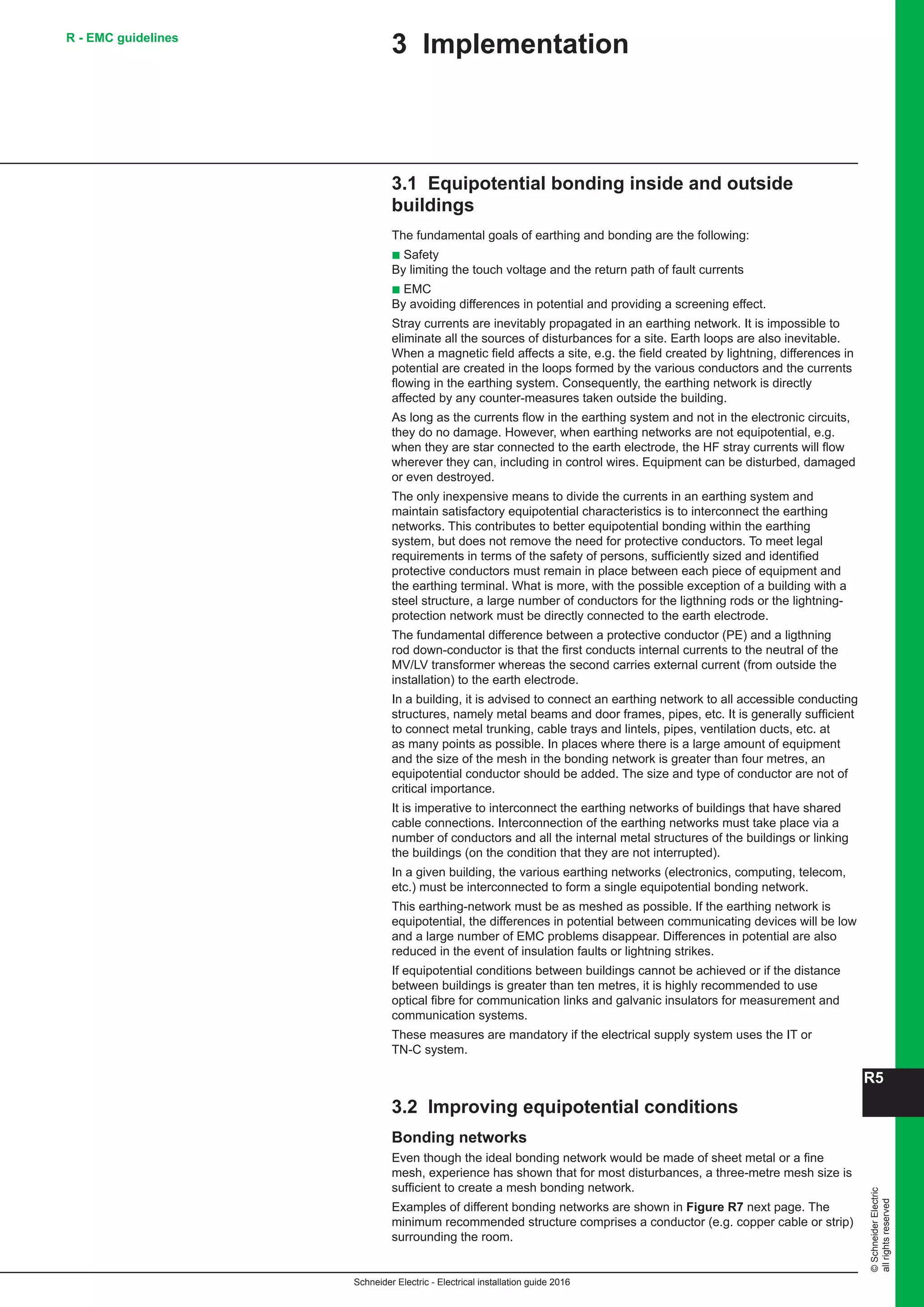
2.1.1 Types of distribution switchboards
Distribution switchboards may differ according to the kind of application
and the design principle adopted (notably in the arrangement of the busbars).
Distribution switchboards according to specific applications
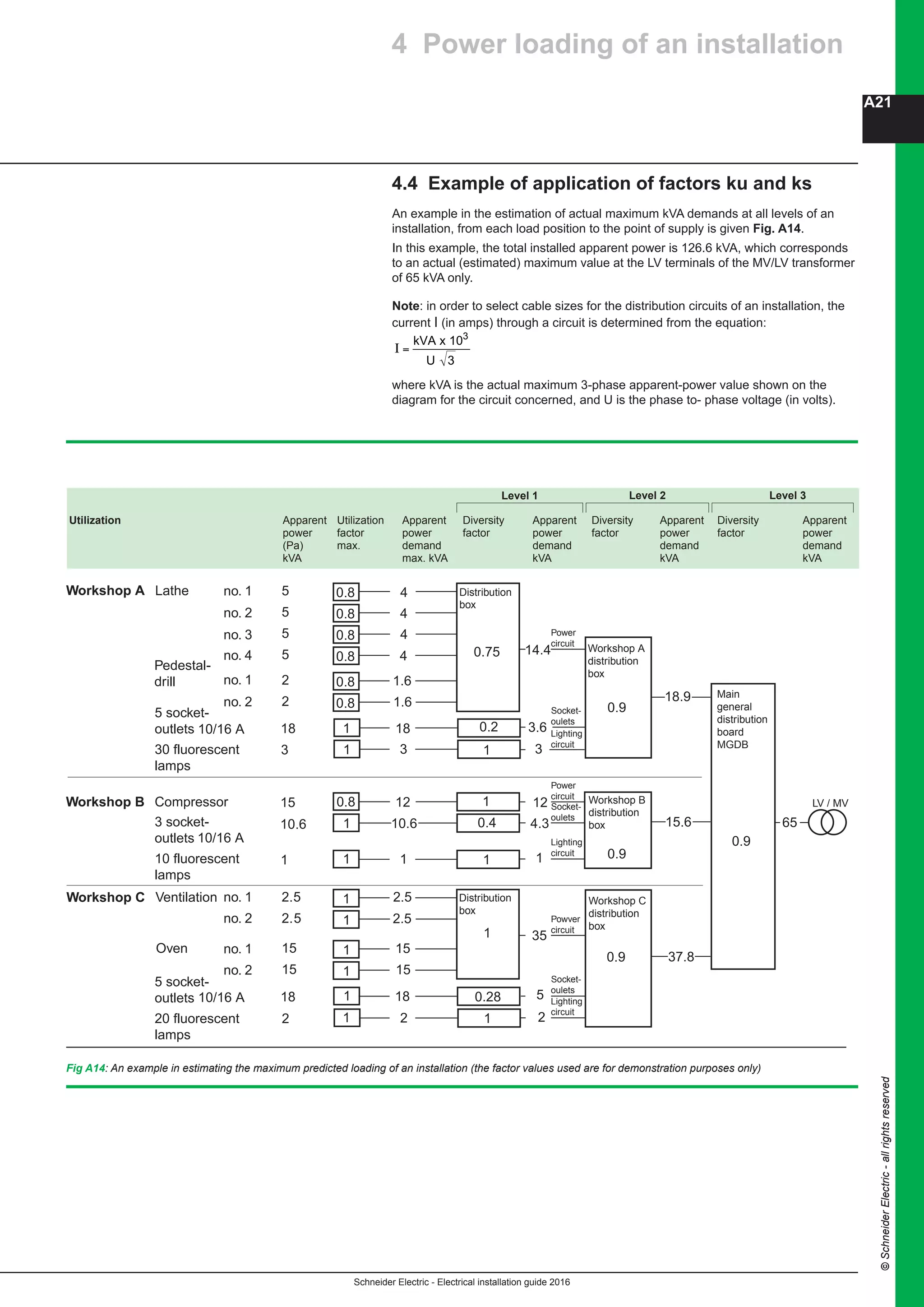
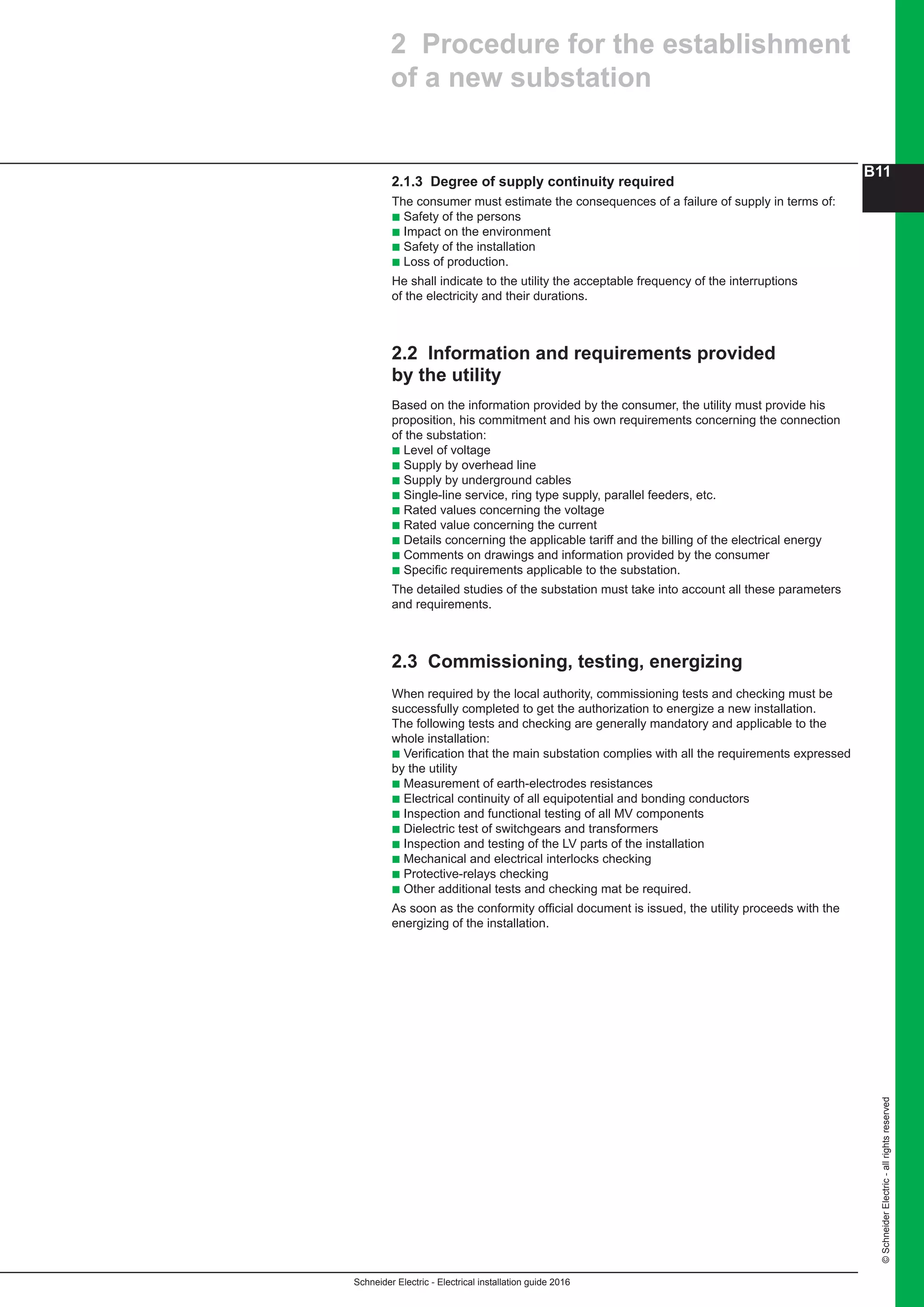
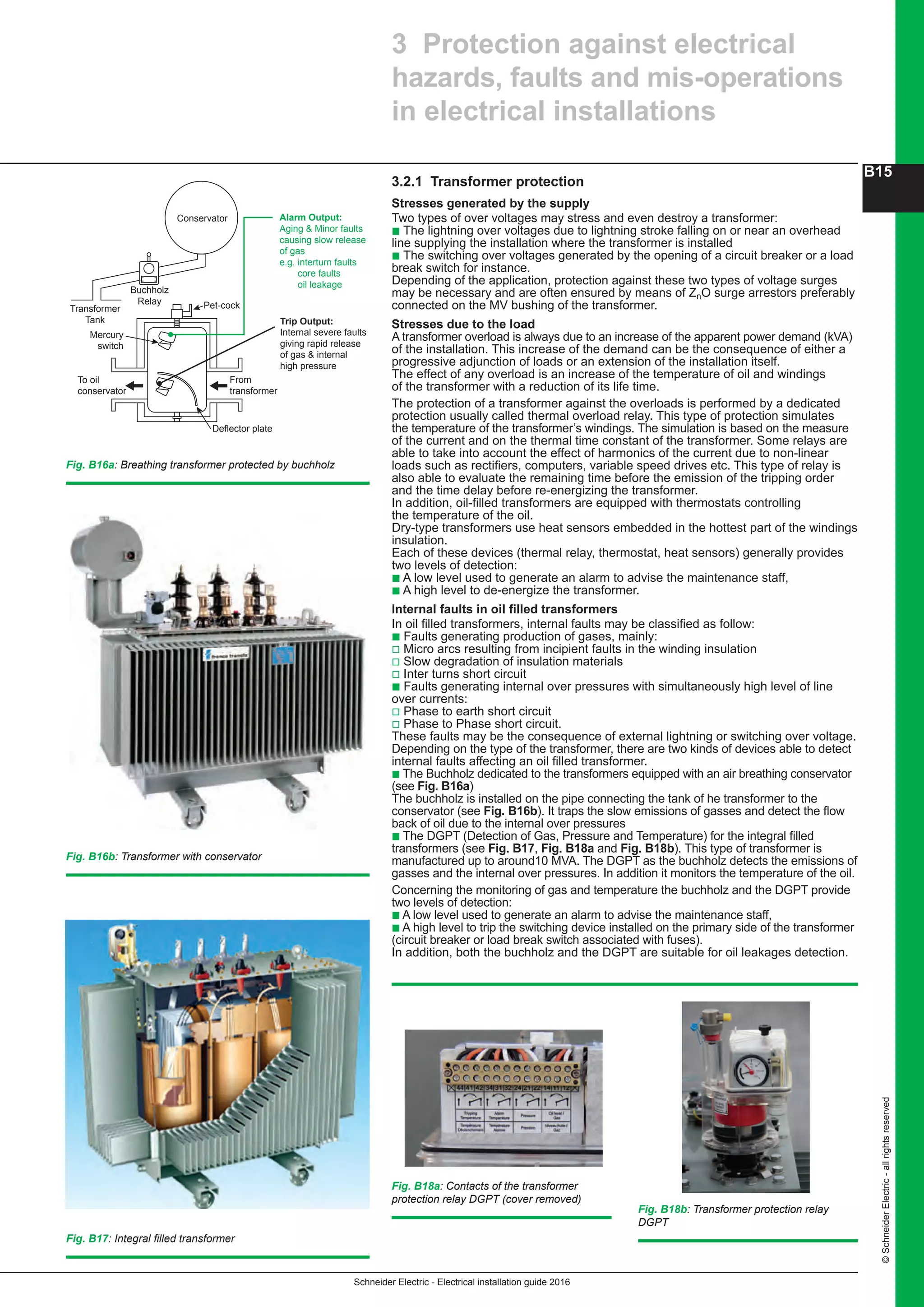
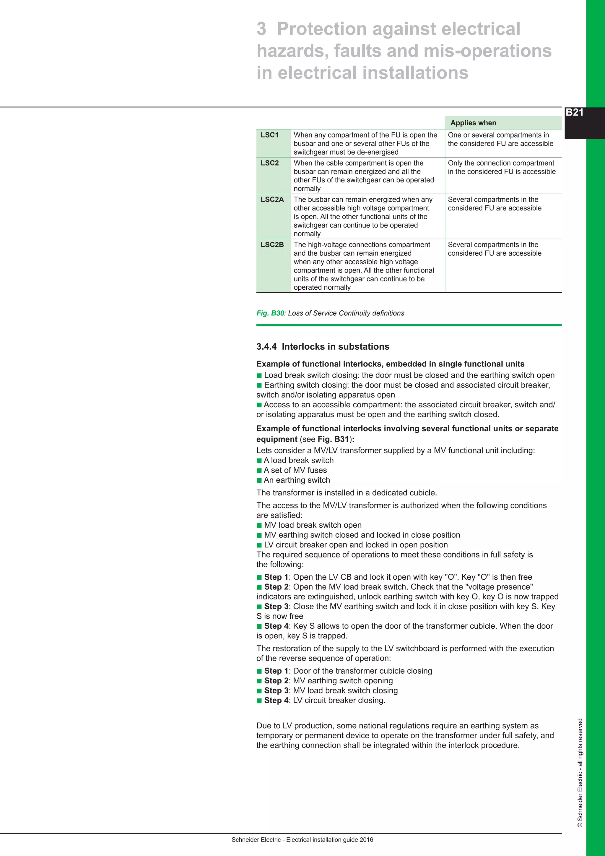
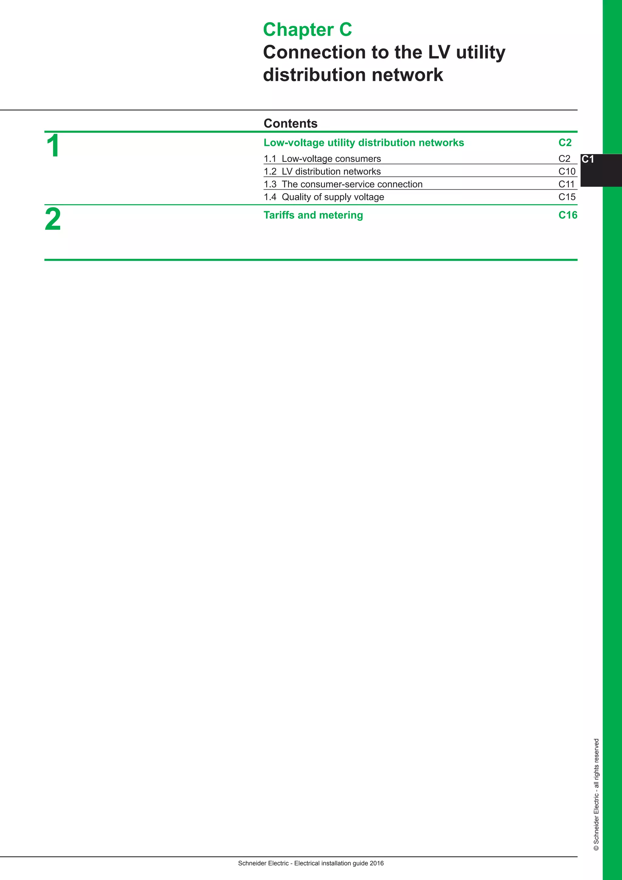
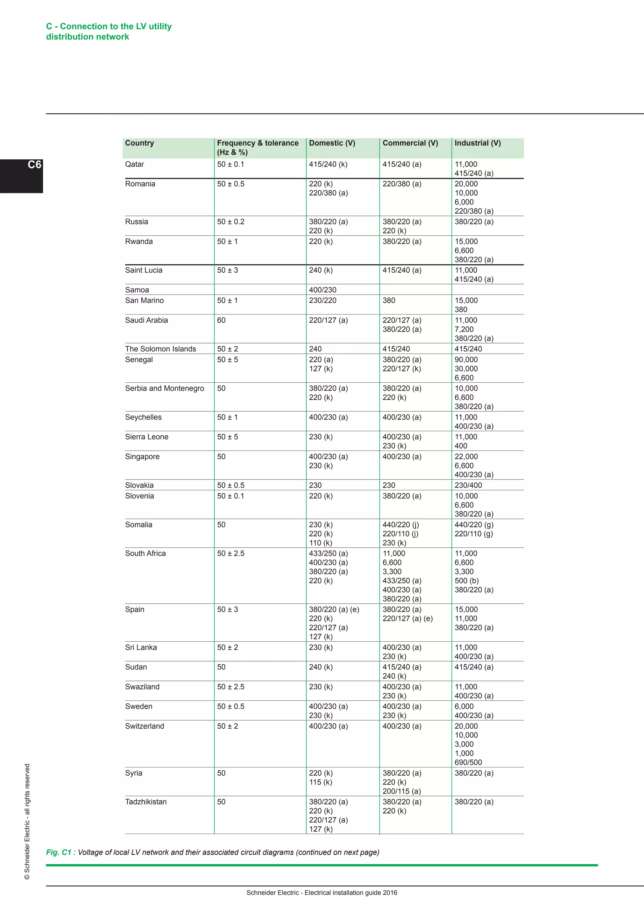
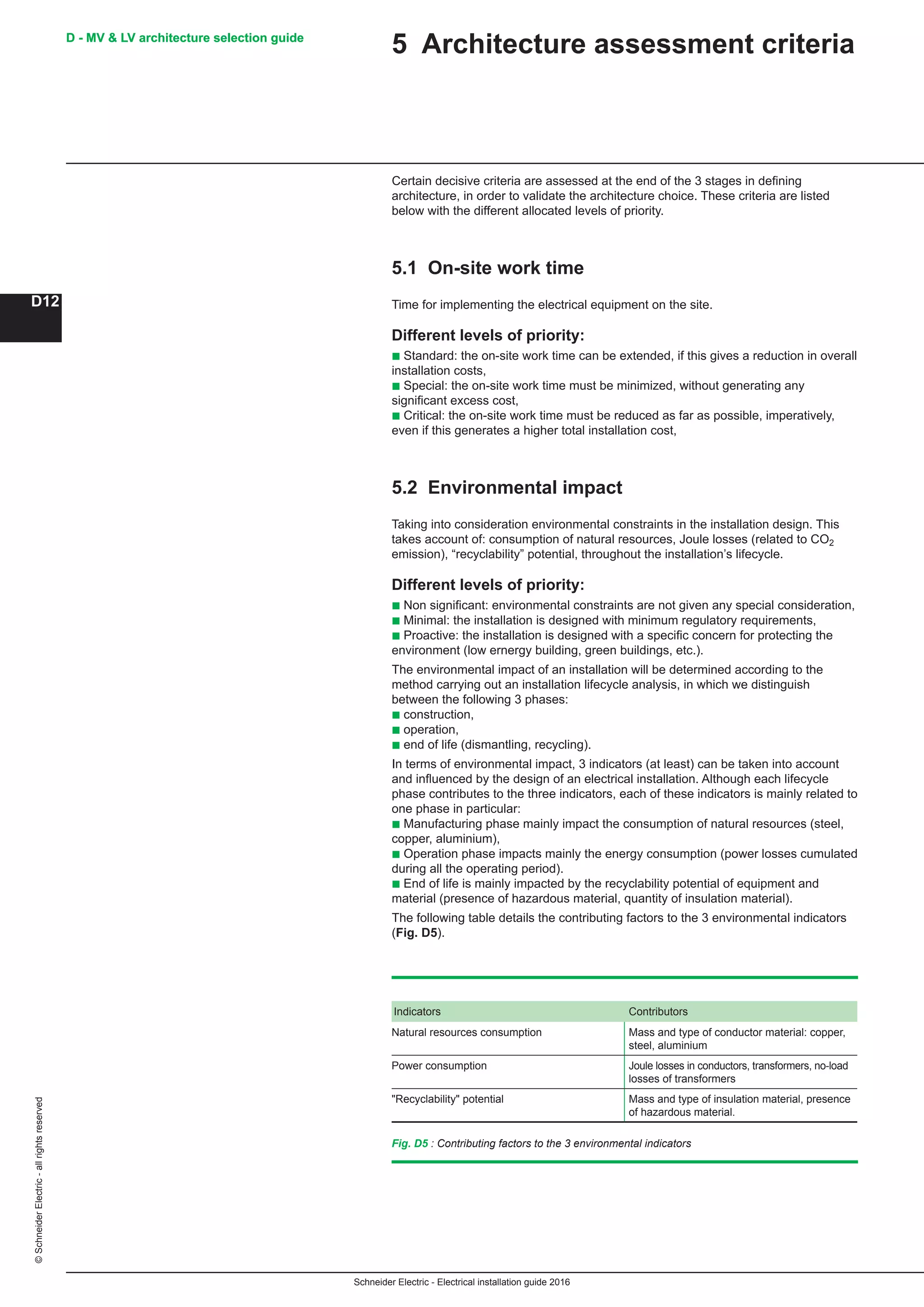
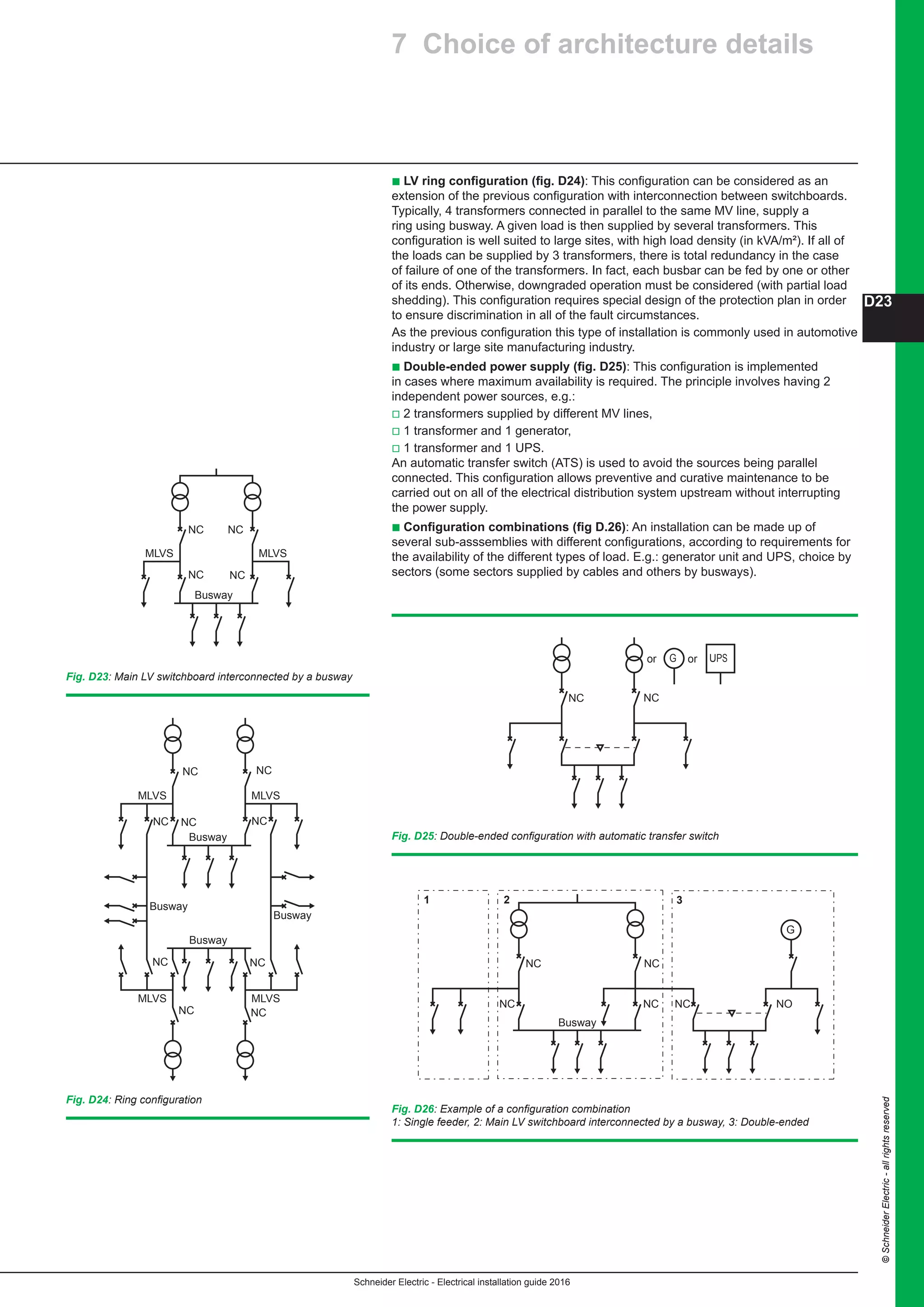
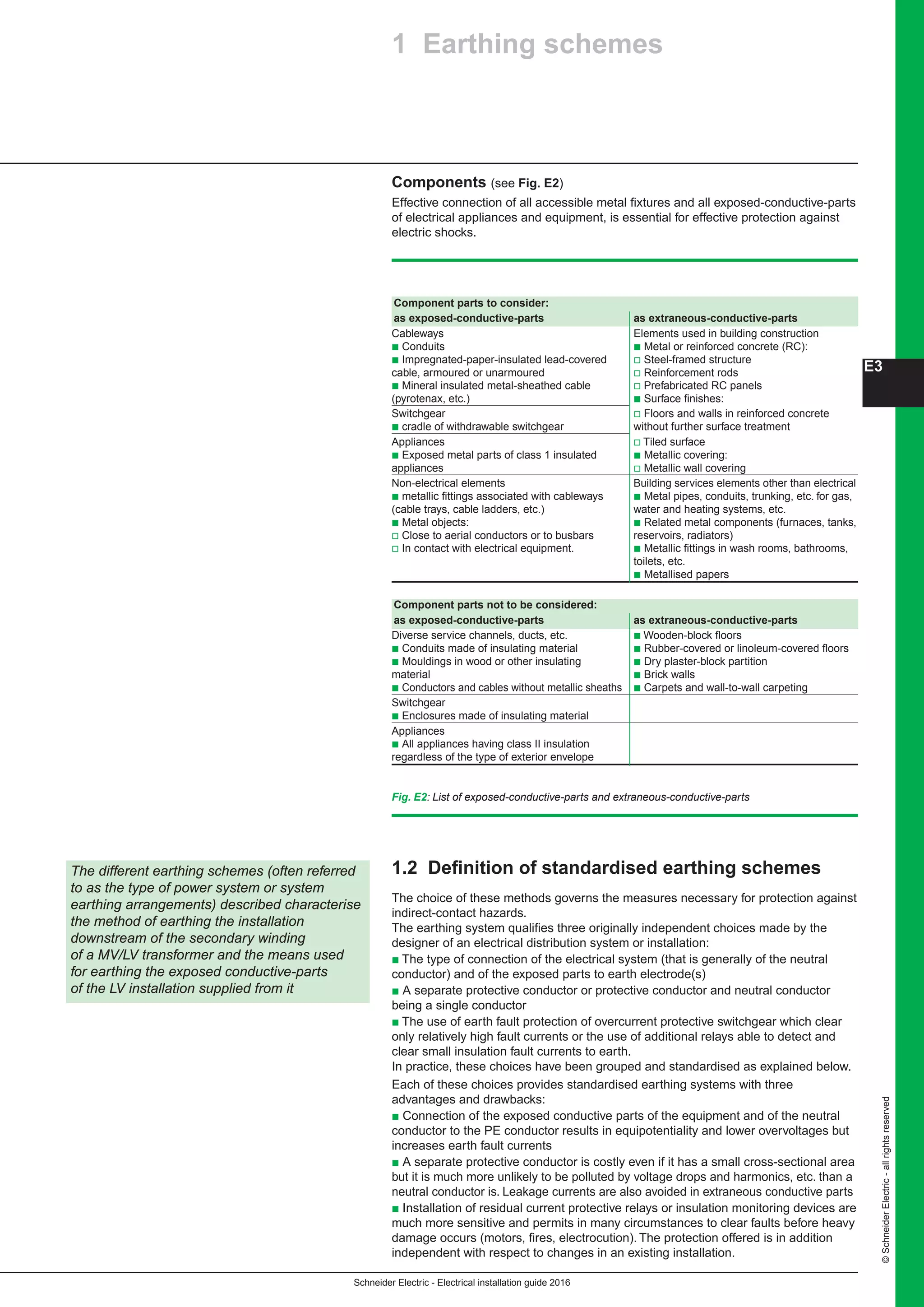
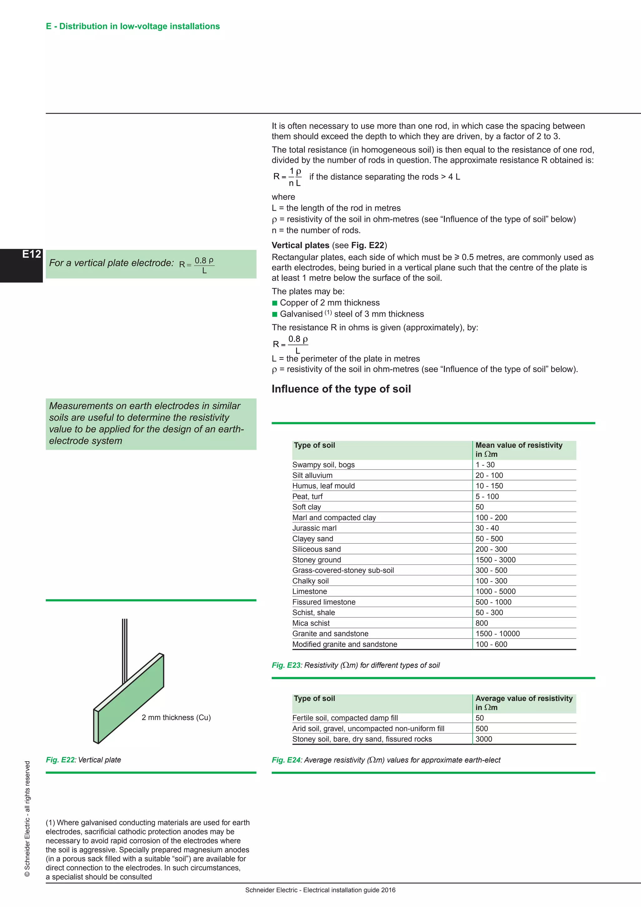
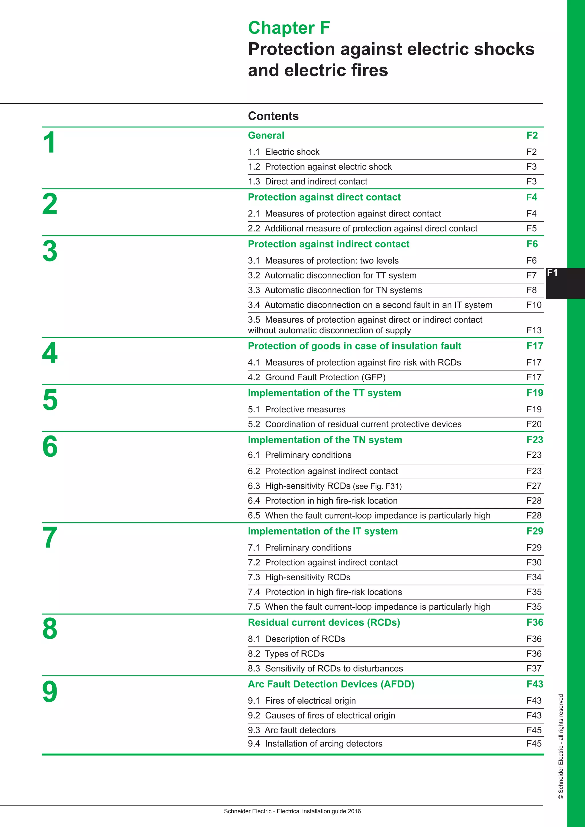
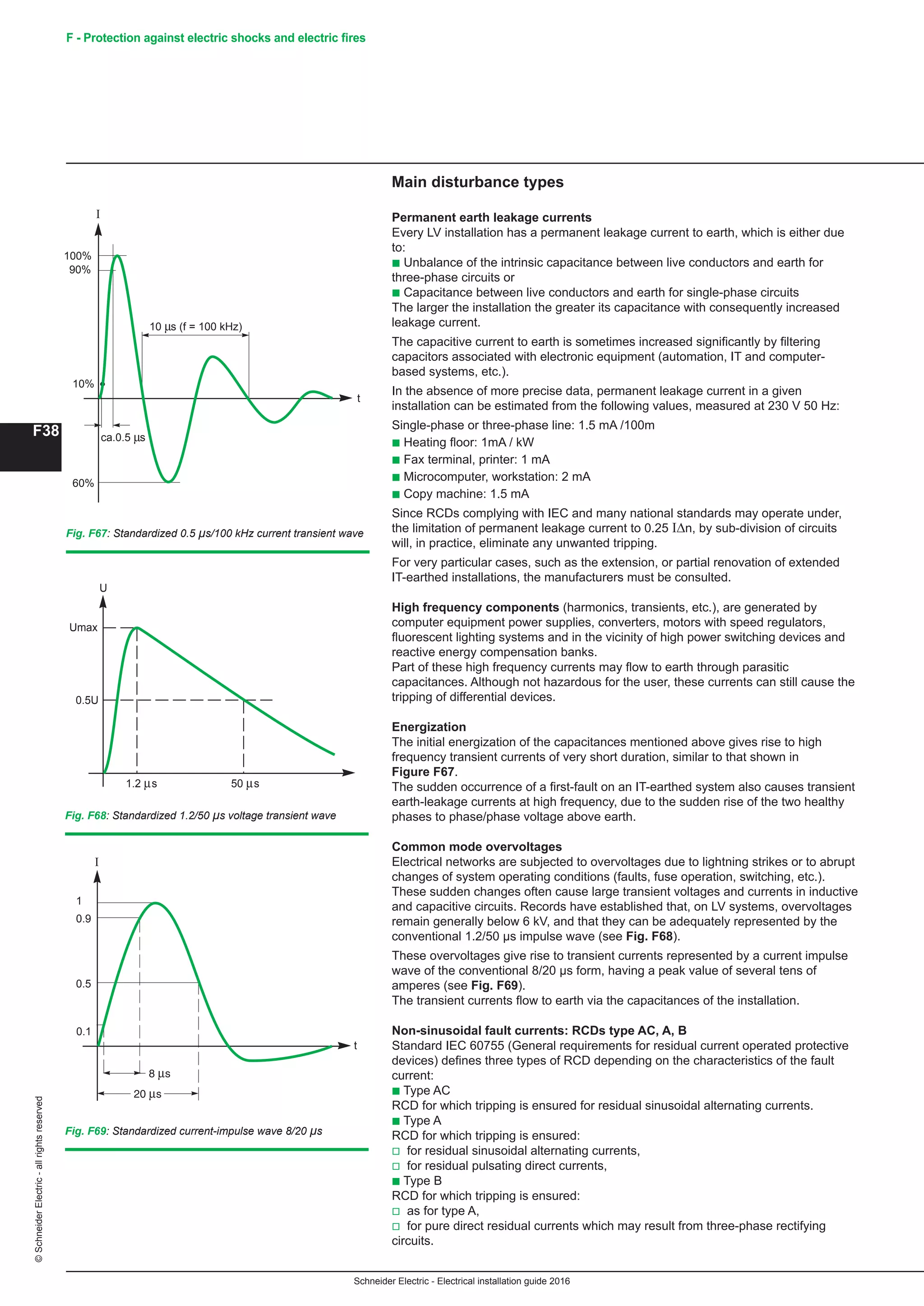
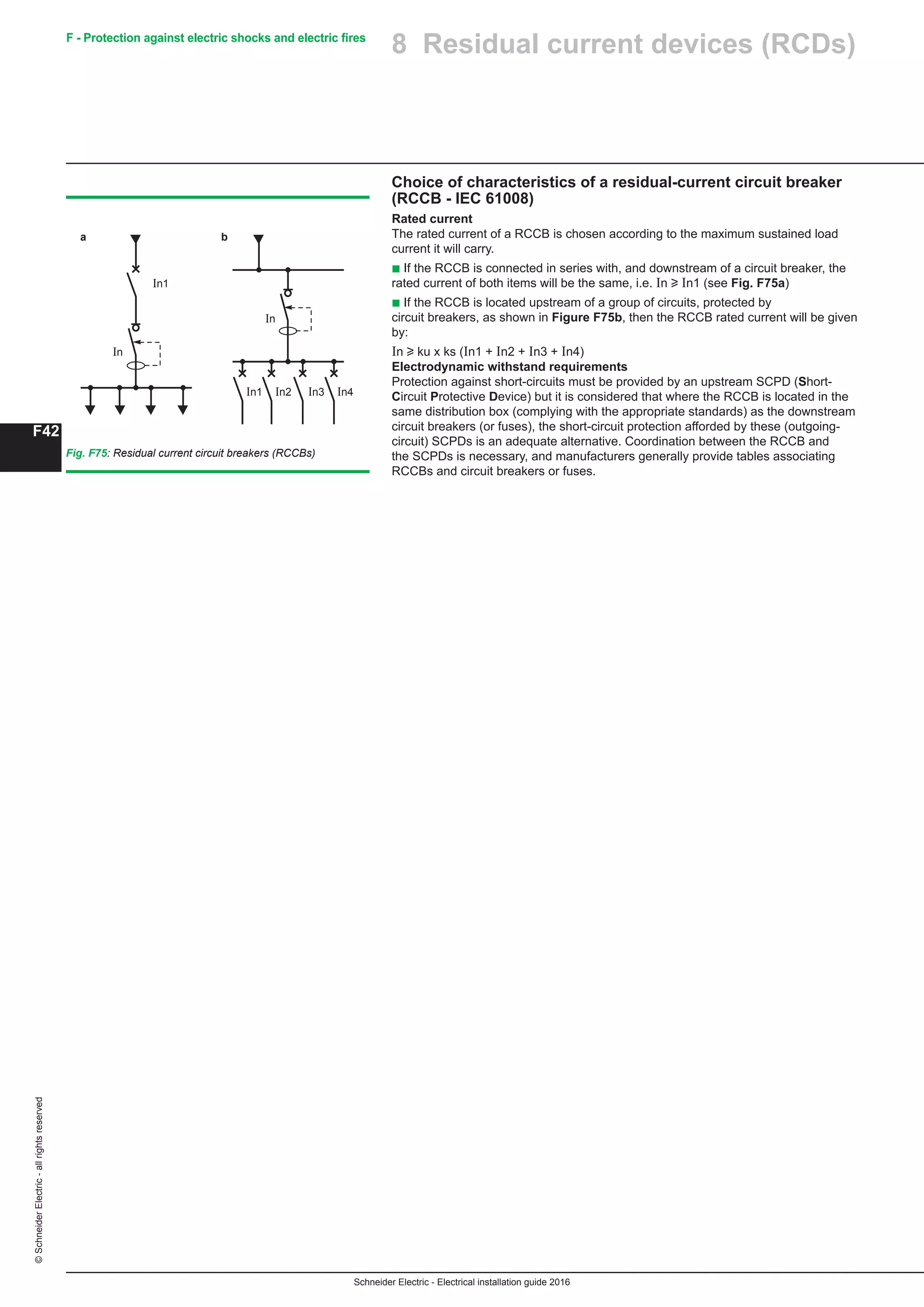
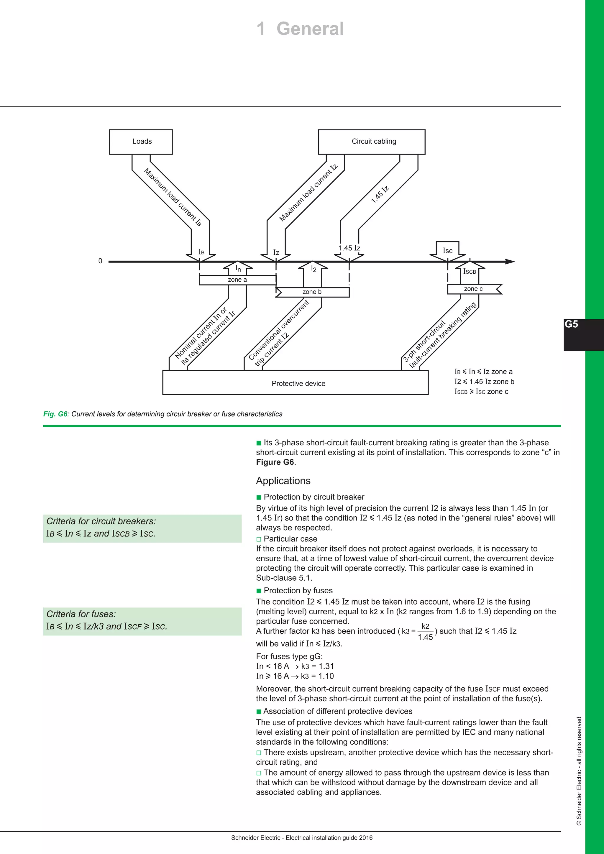
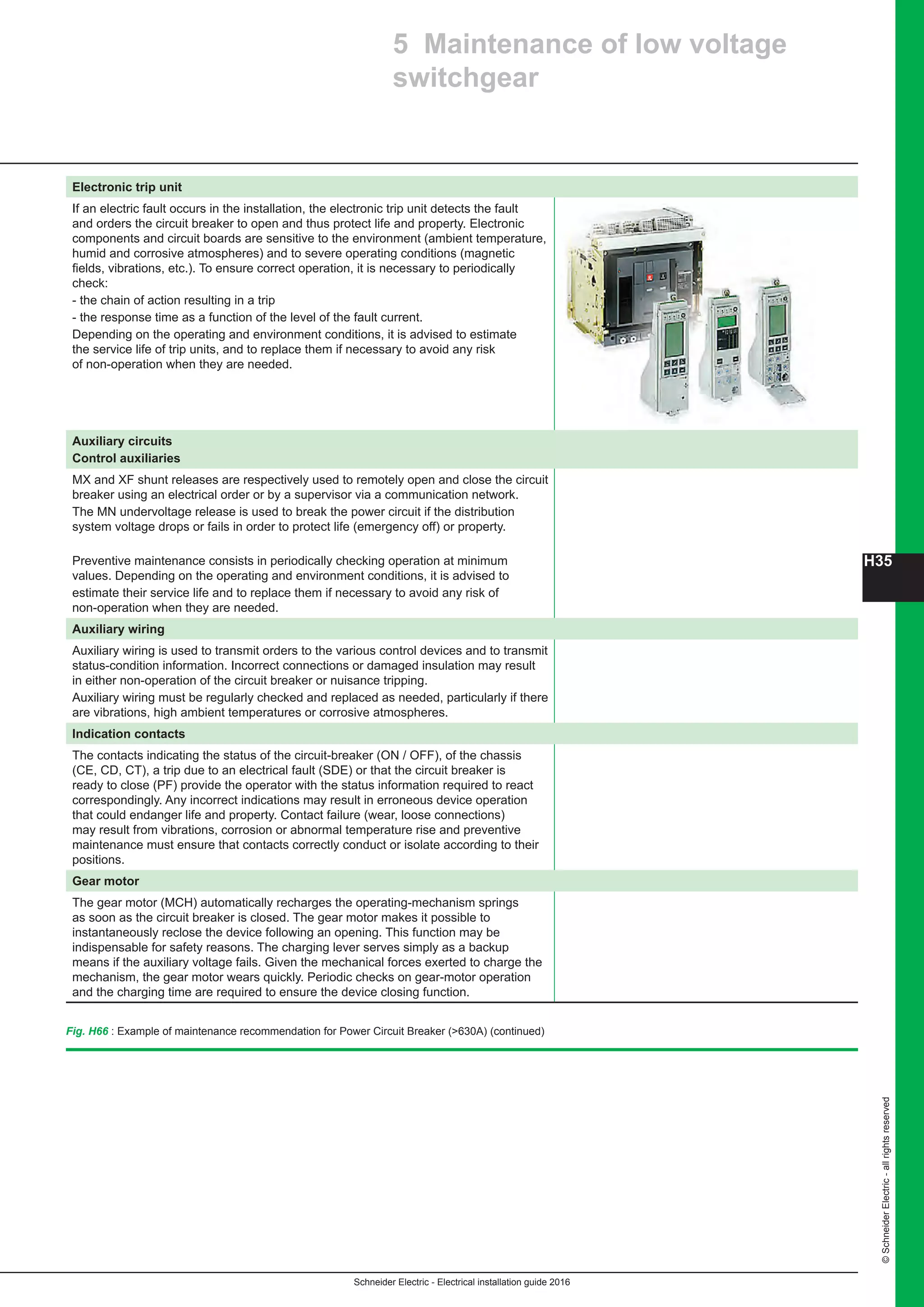
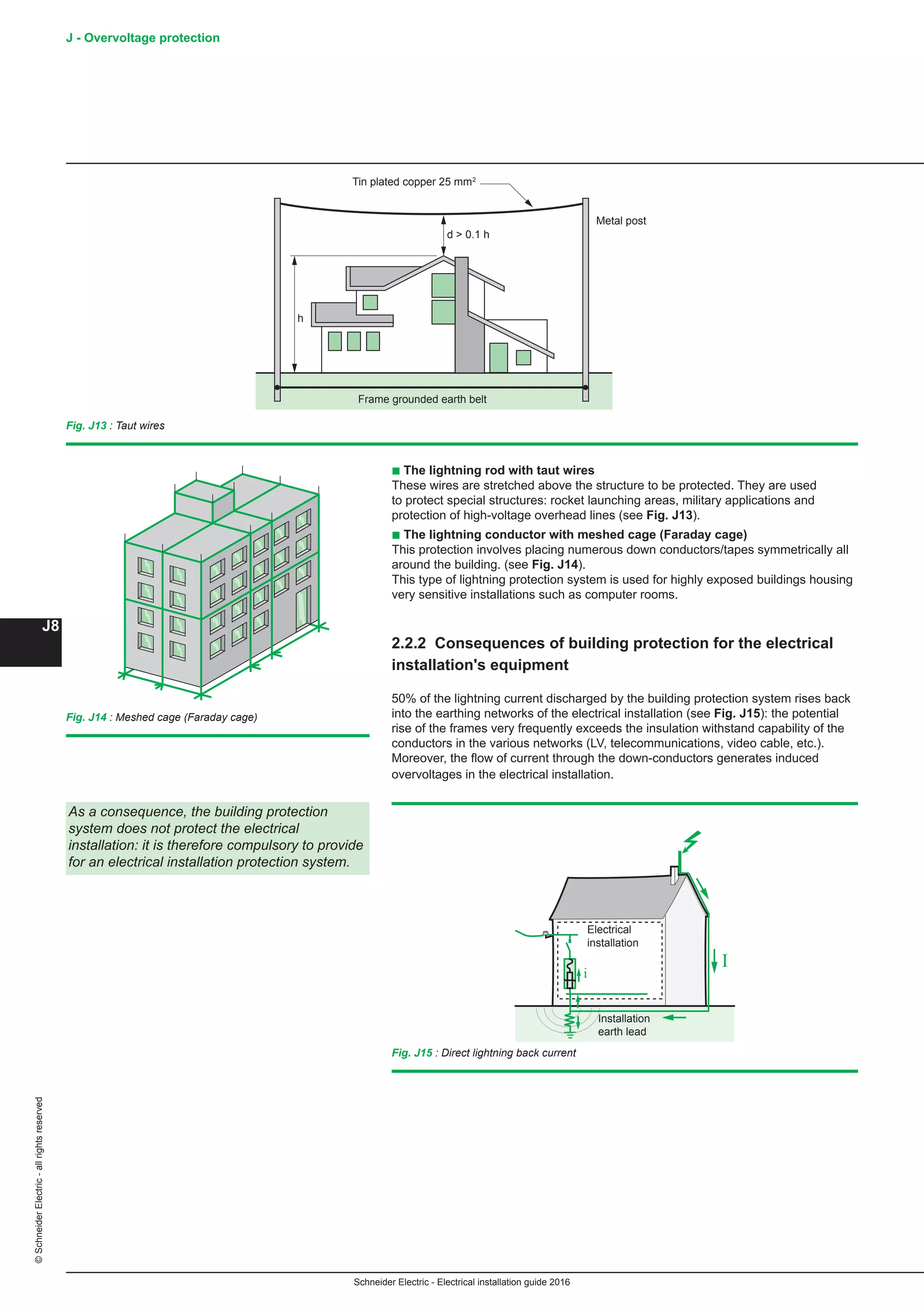
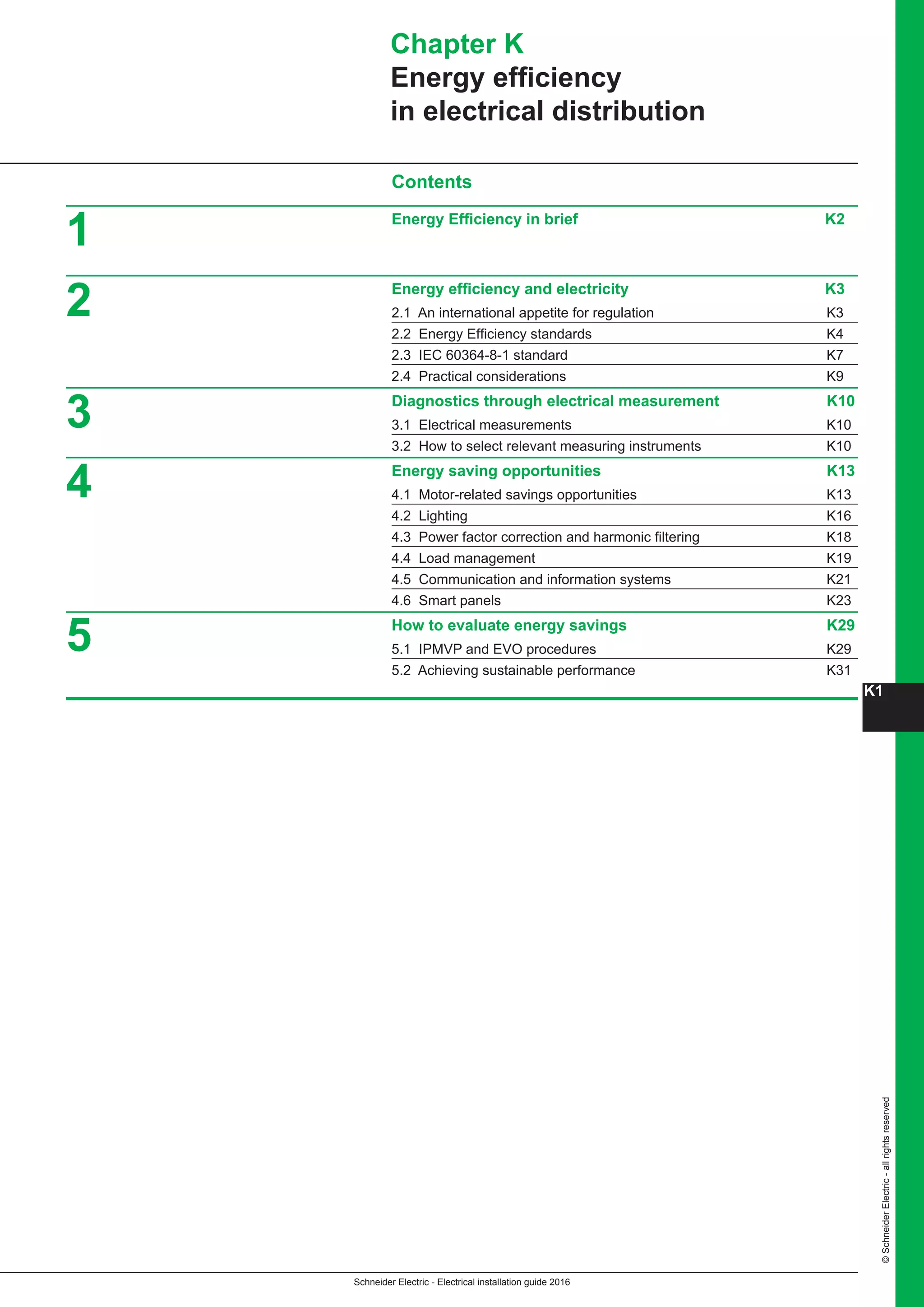
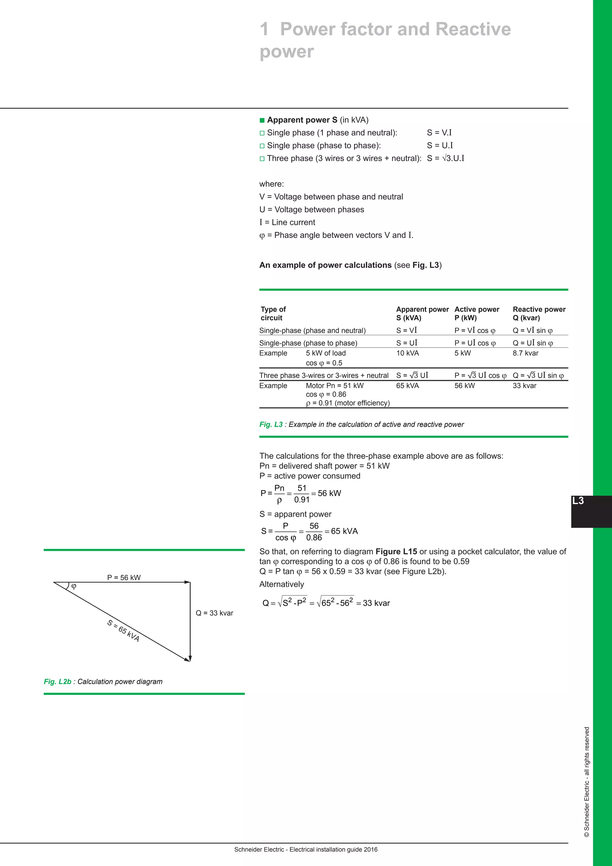
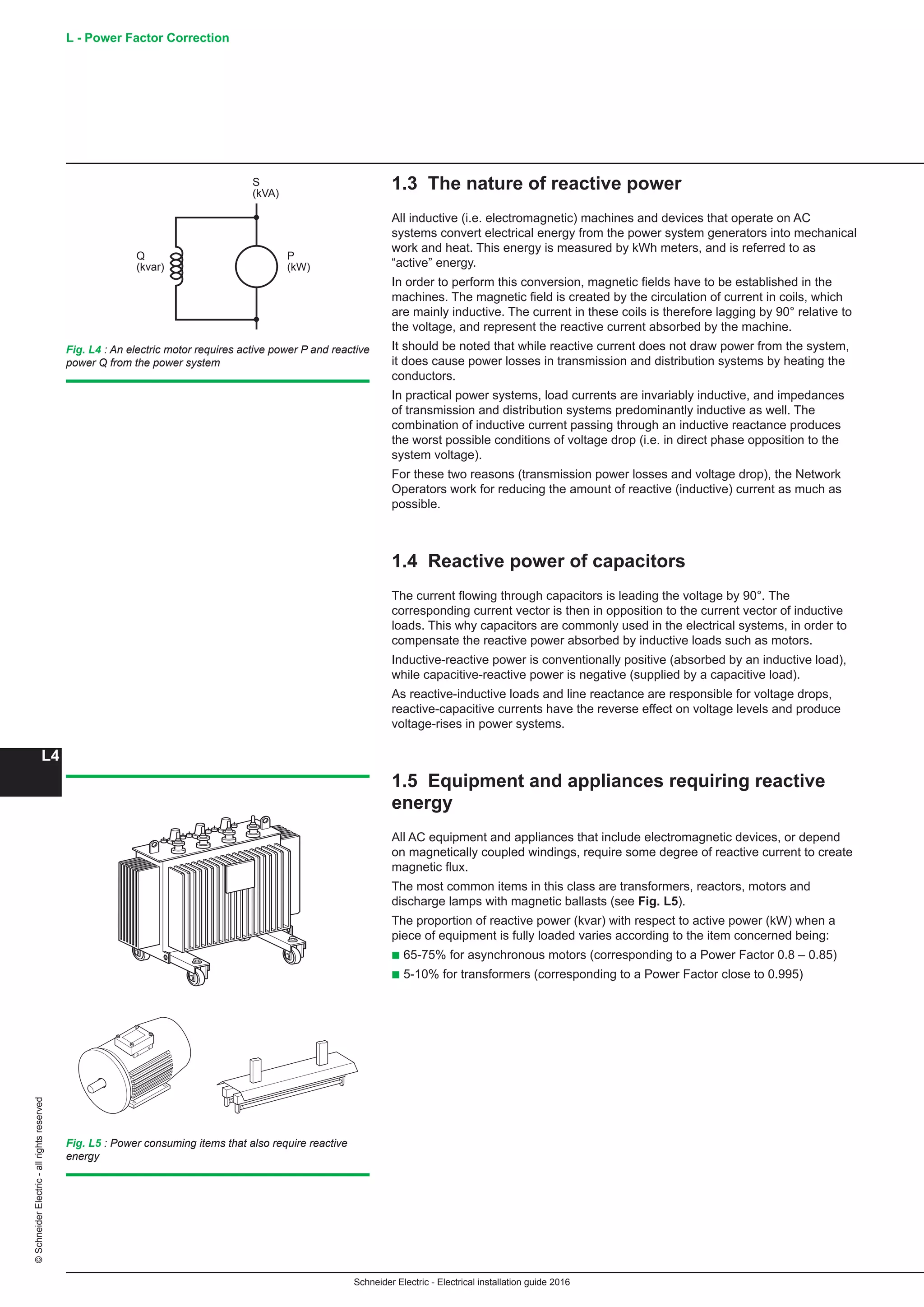
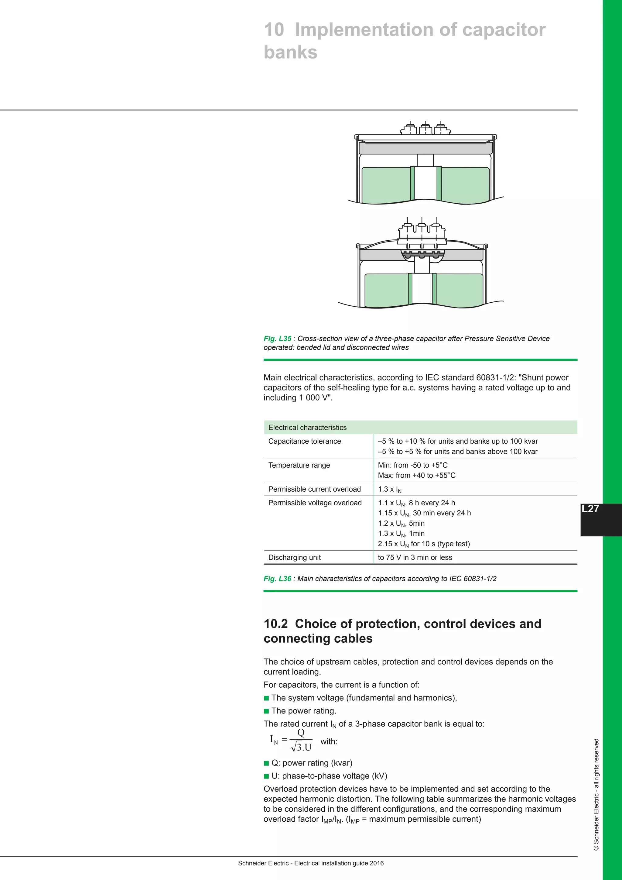
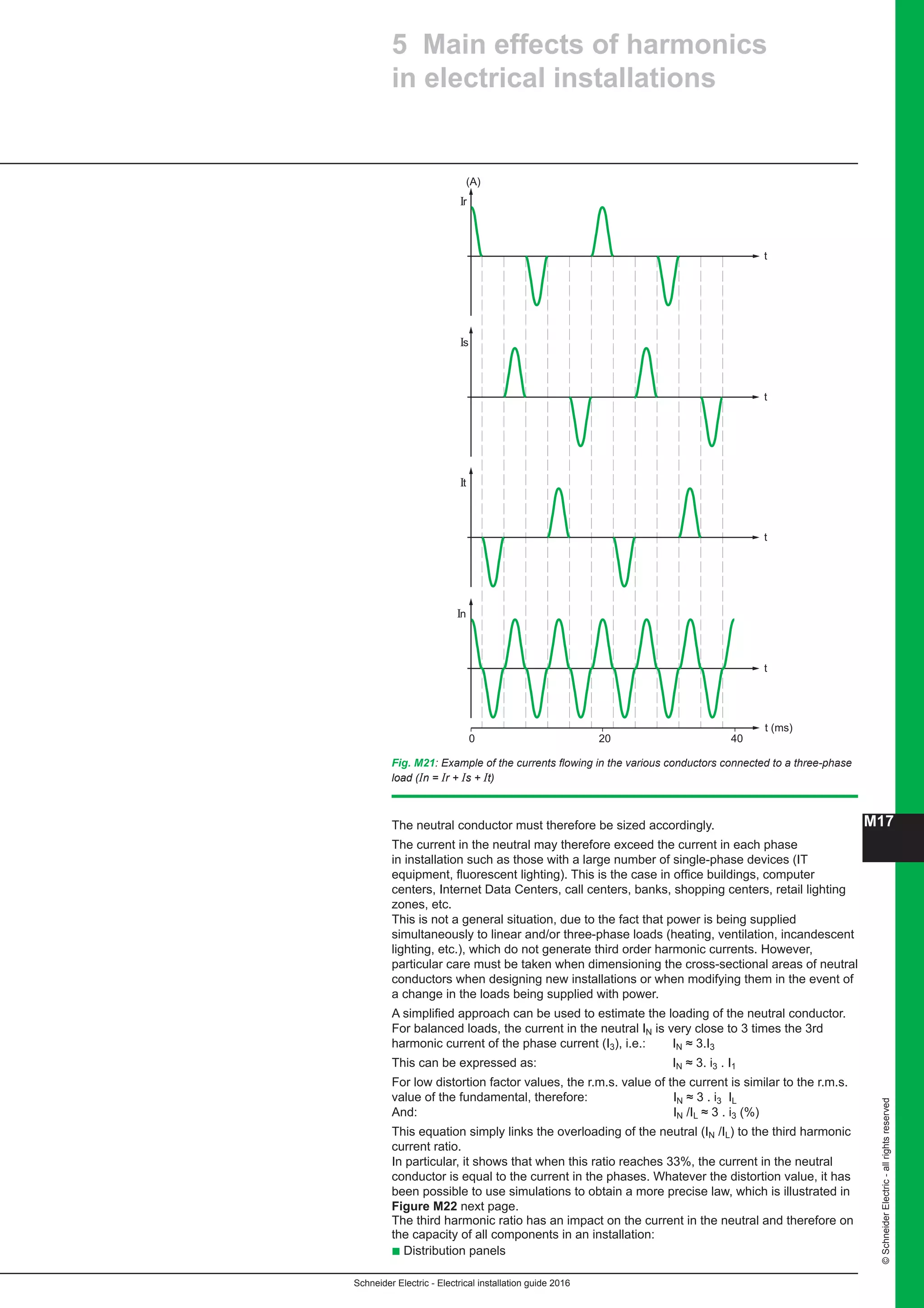
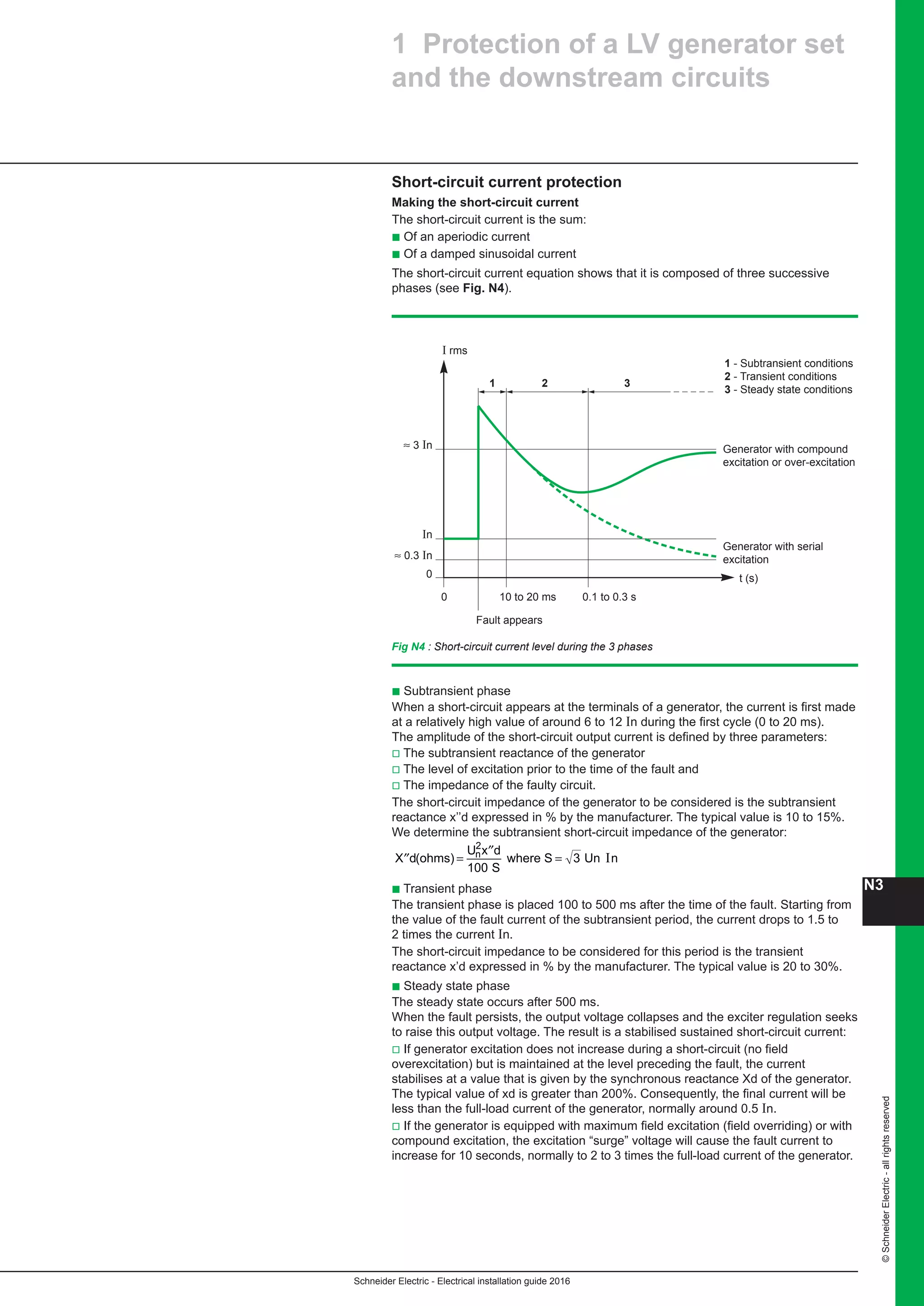
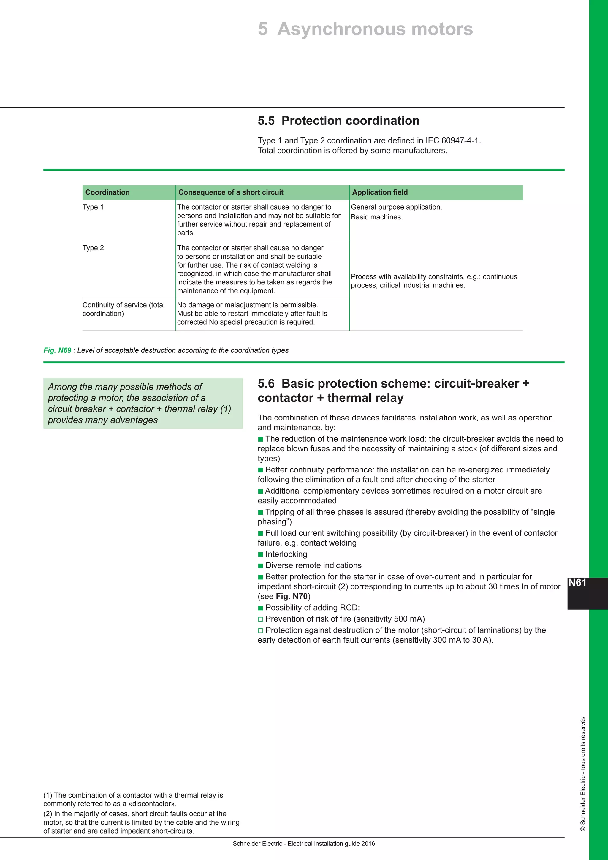
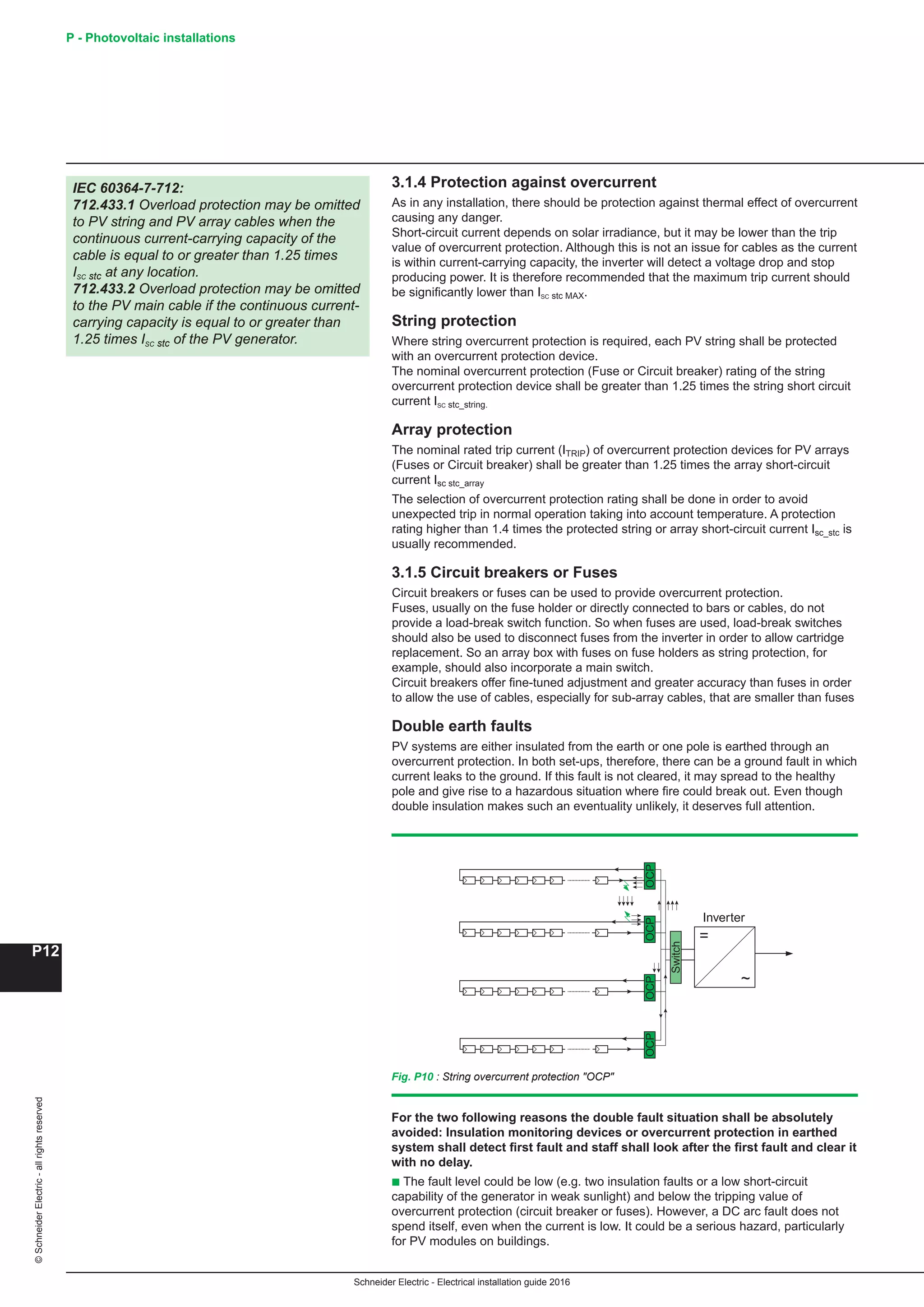
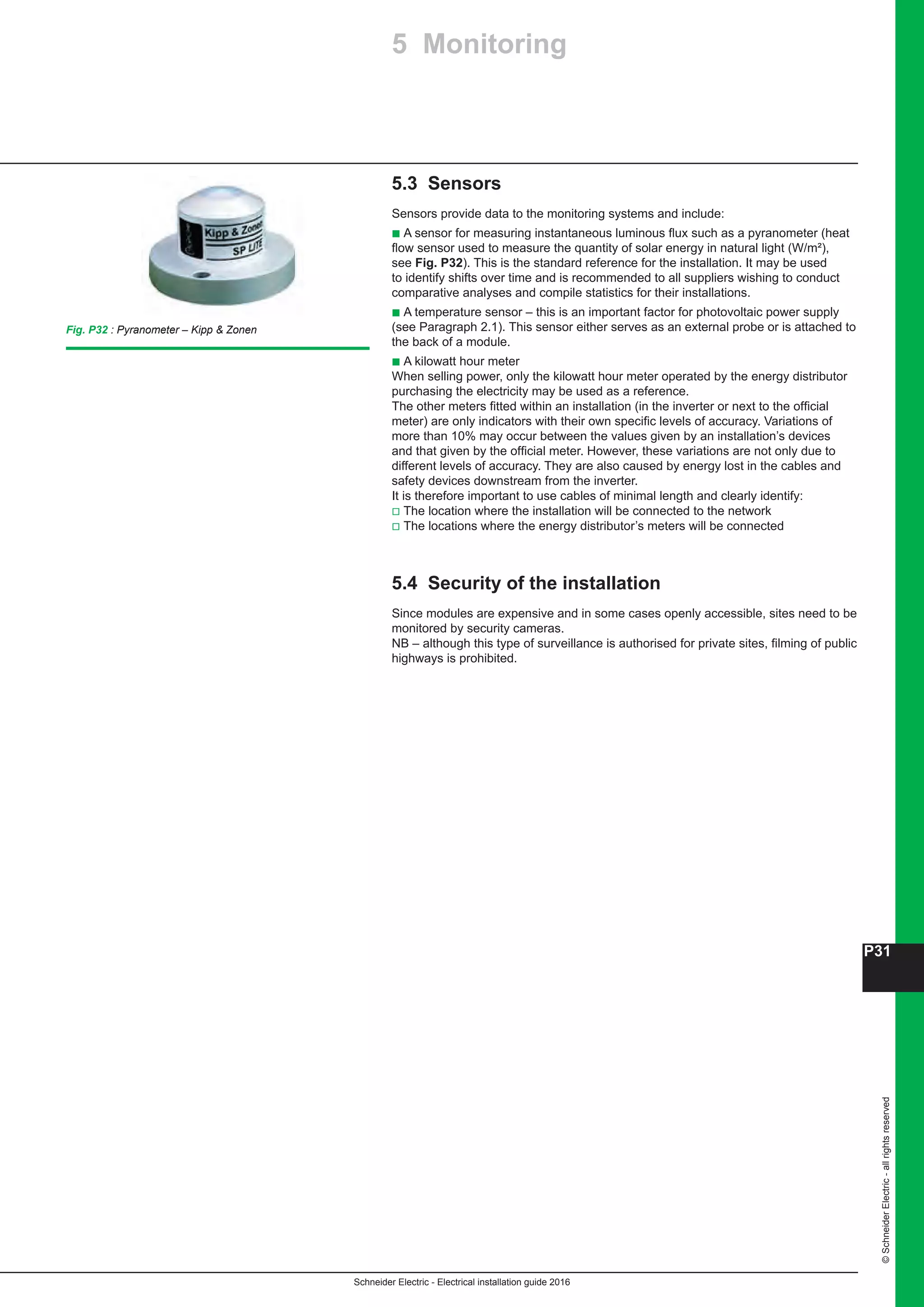
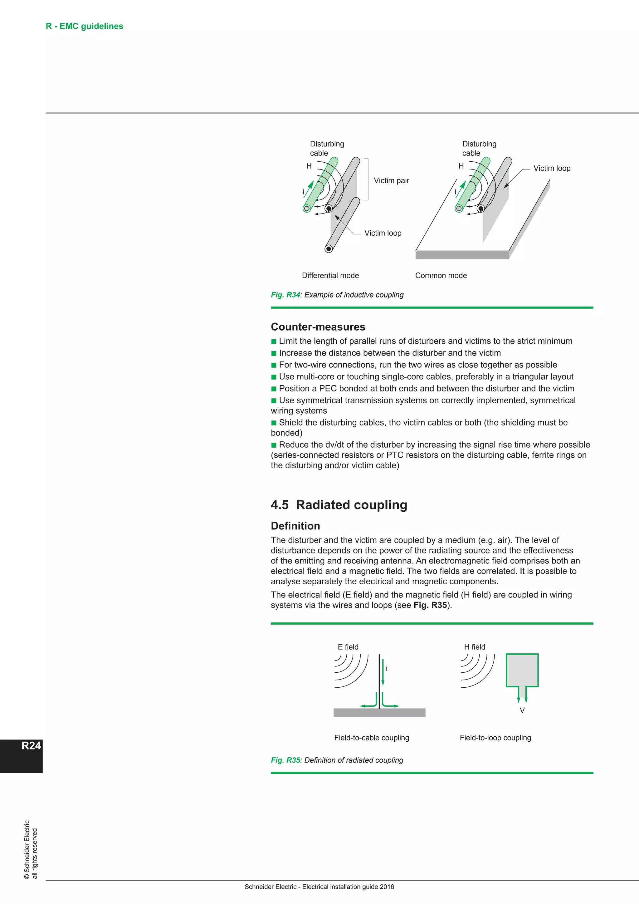
The principal types of distribution switchboards are:
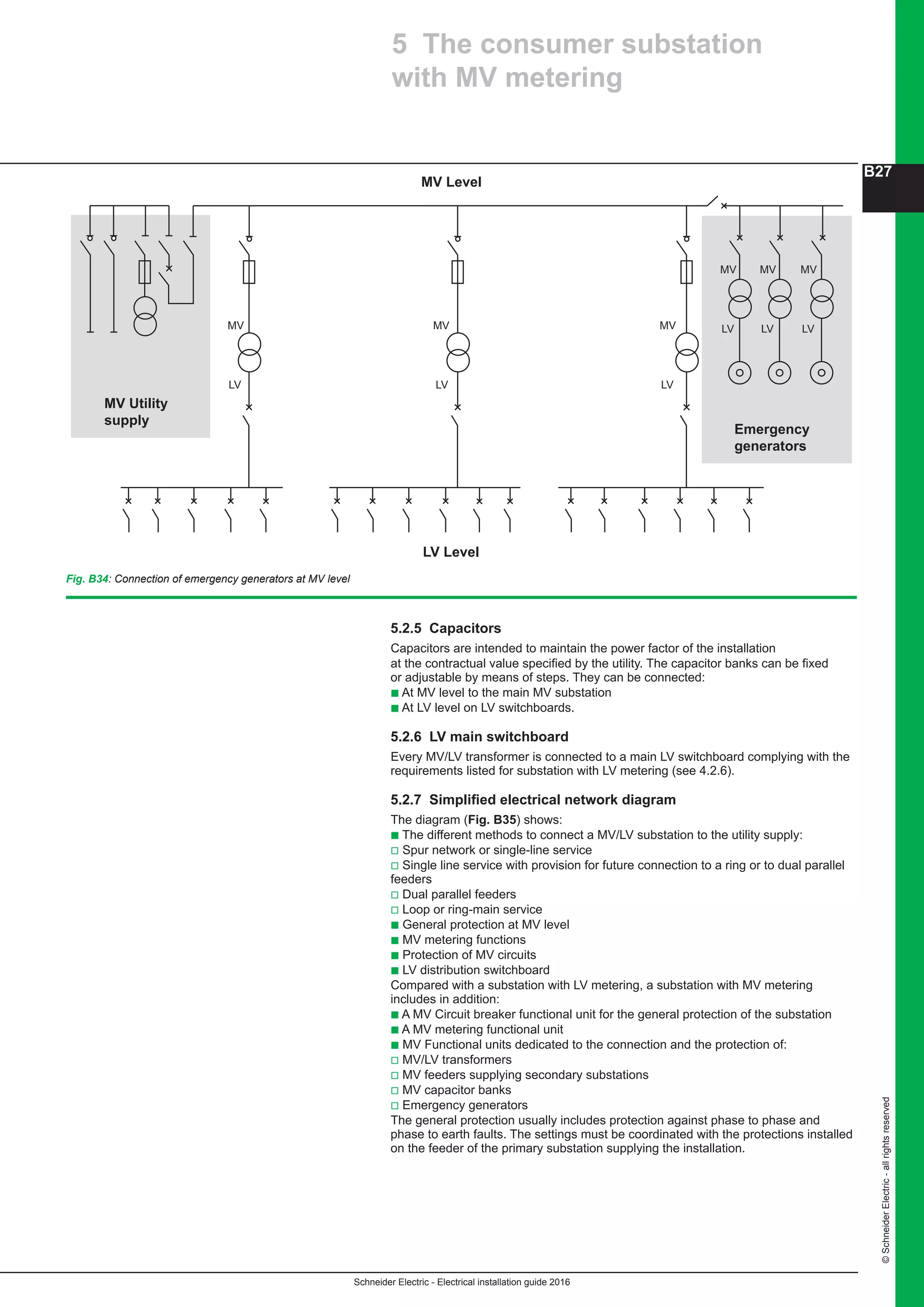
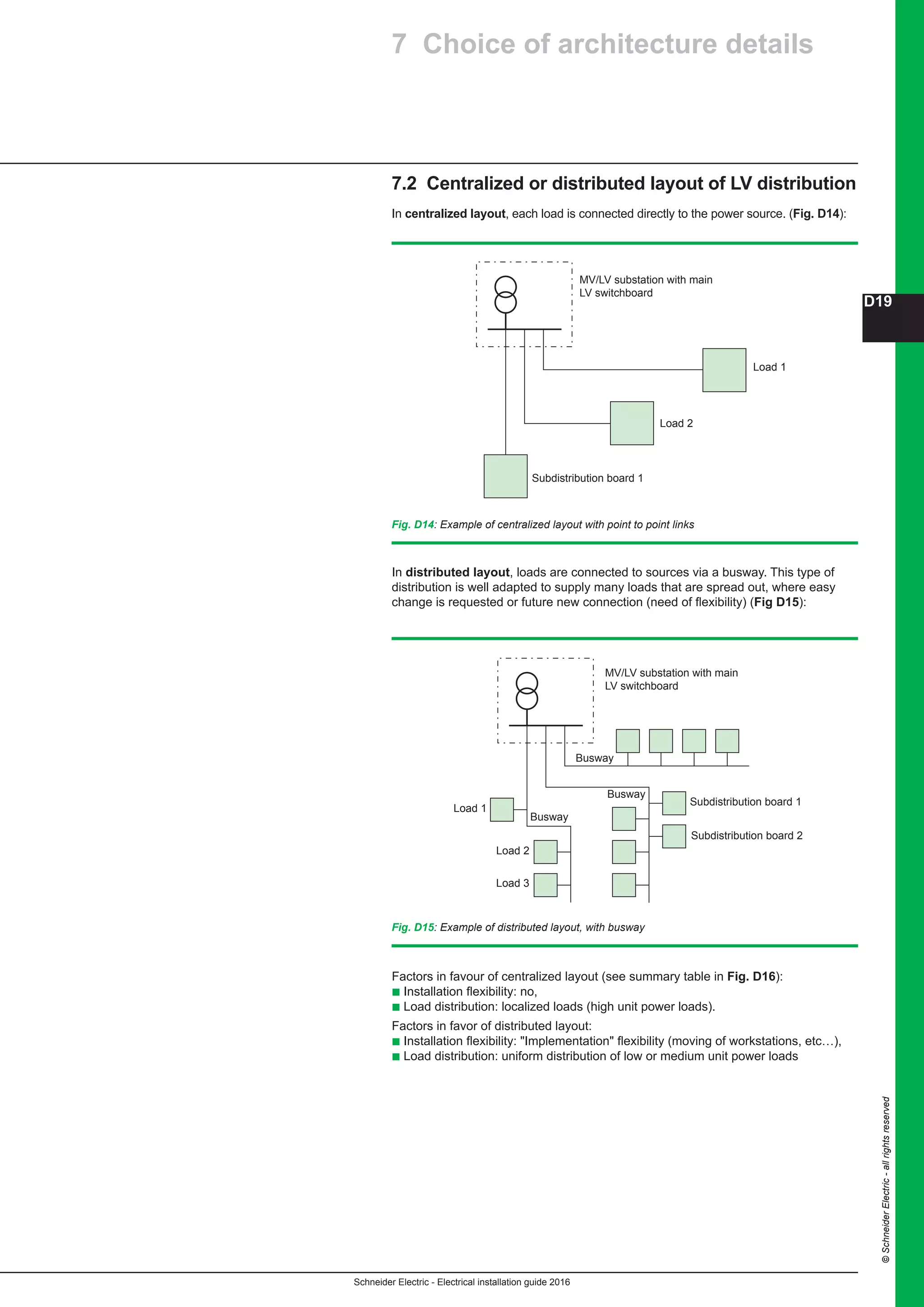
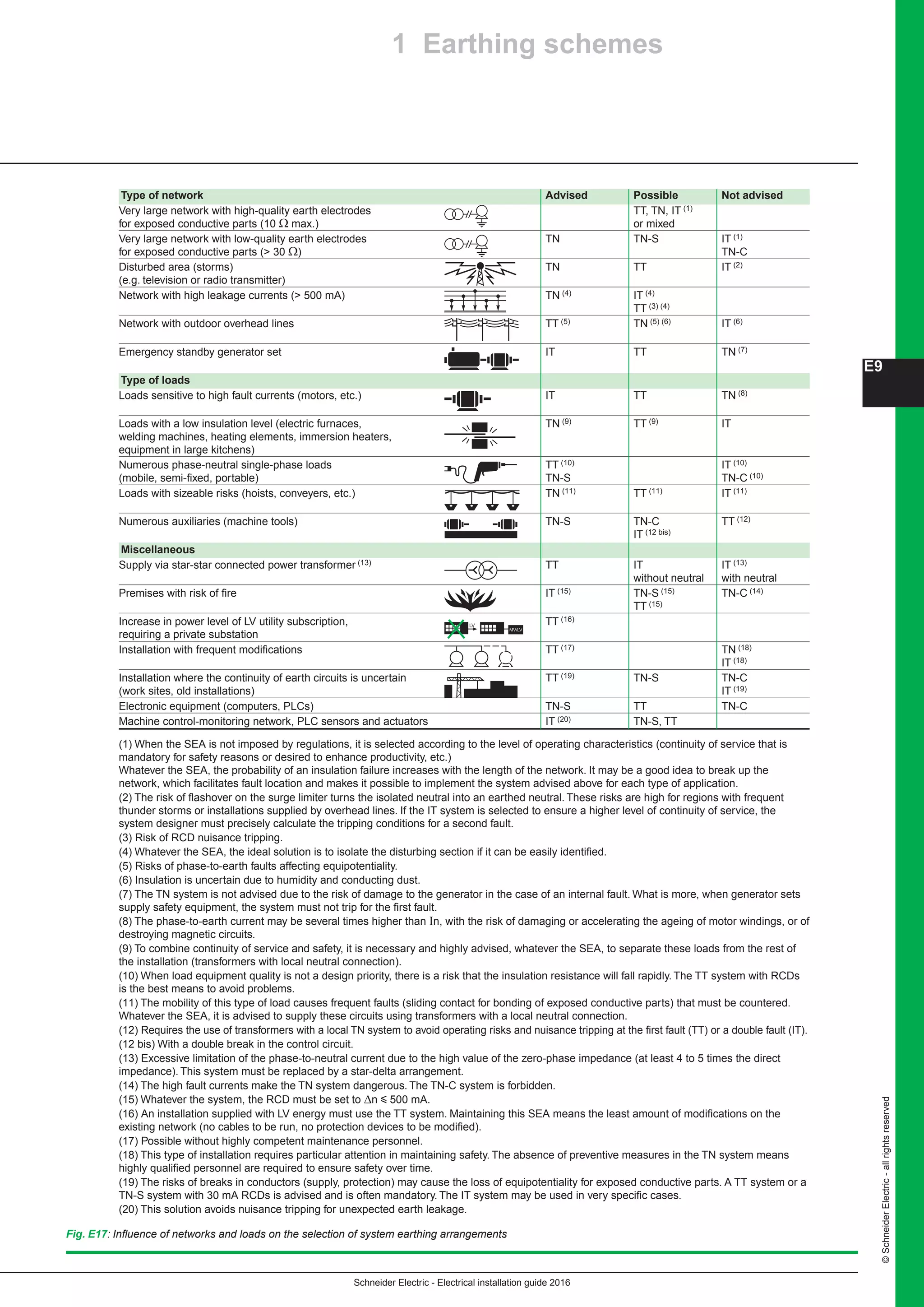
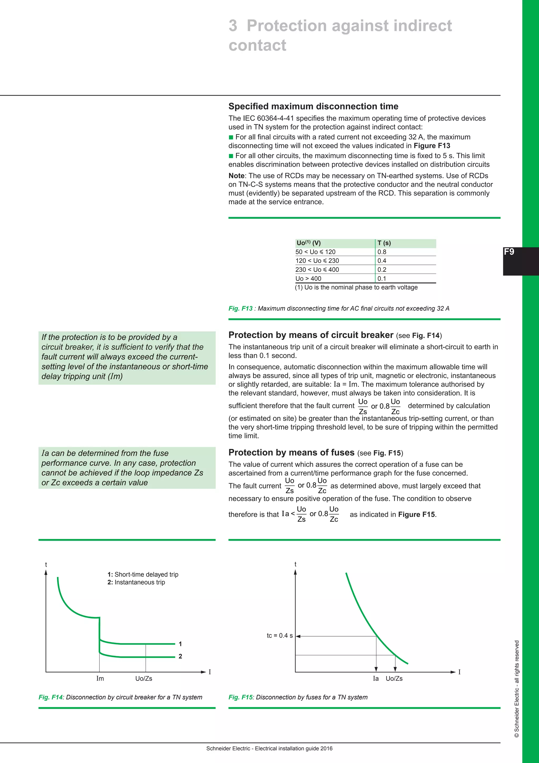
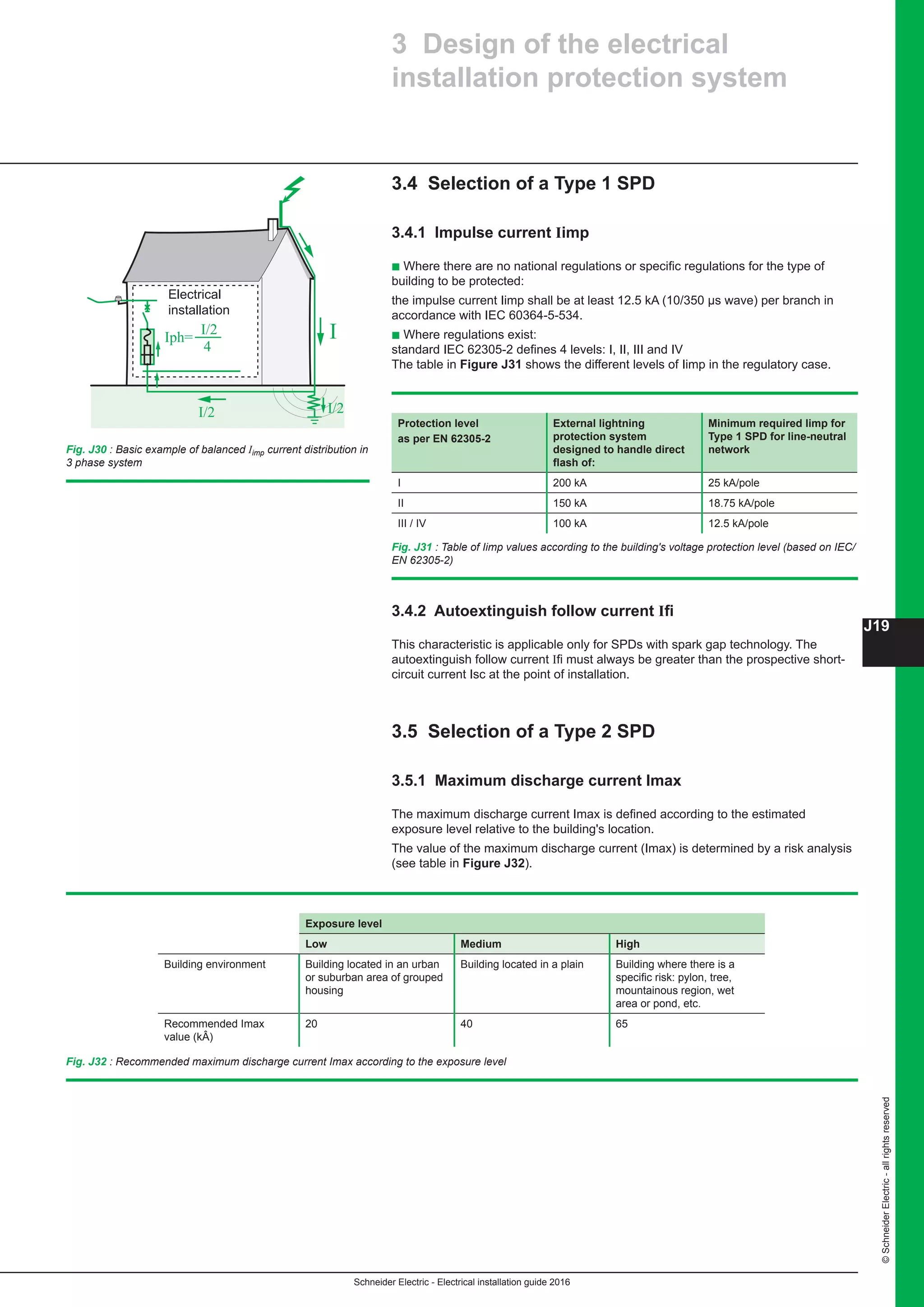
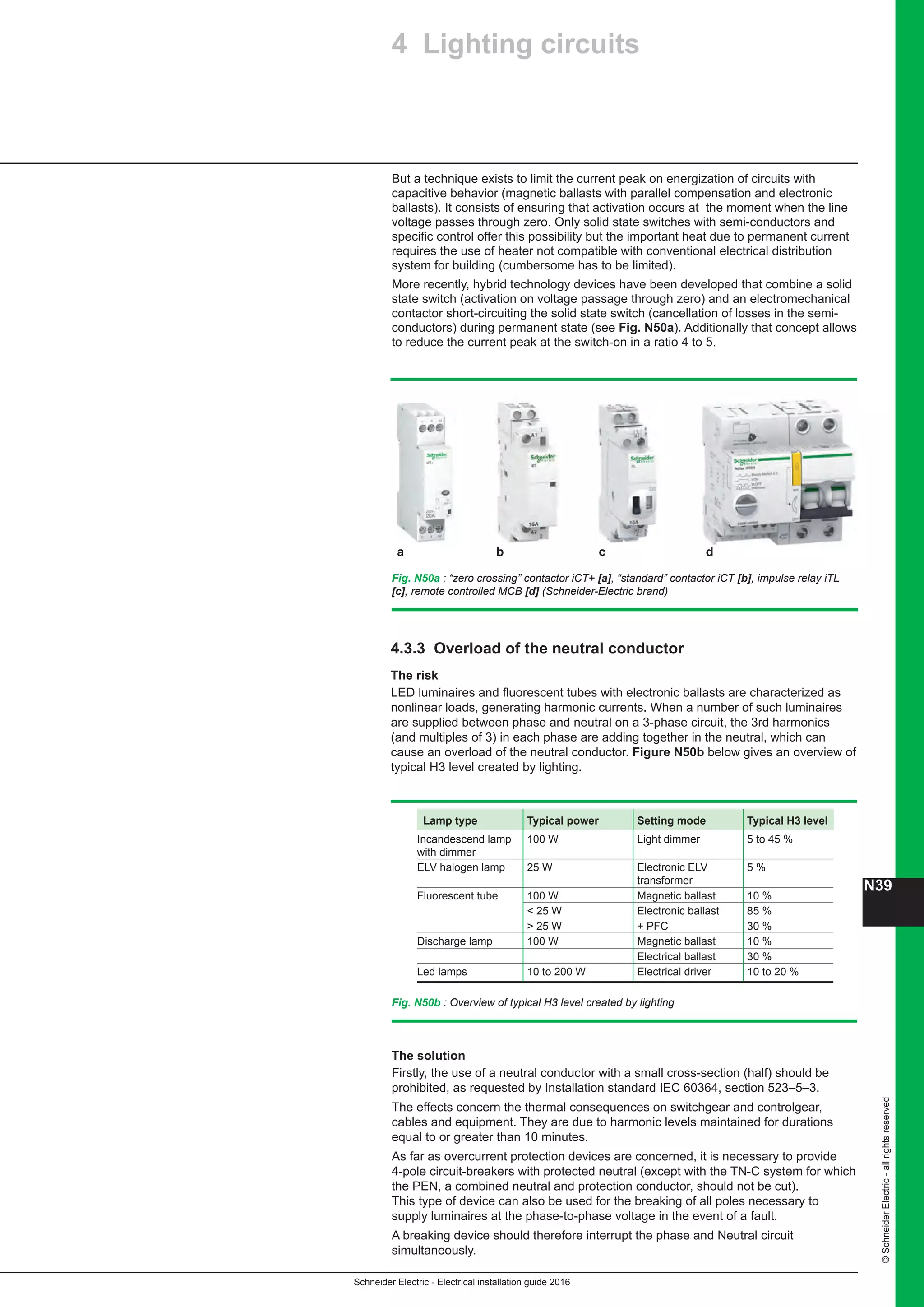
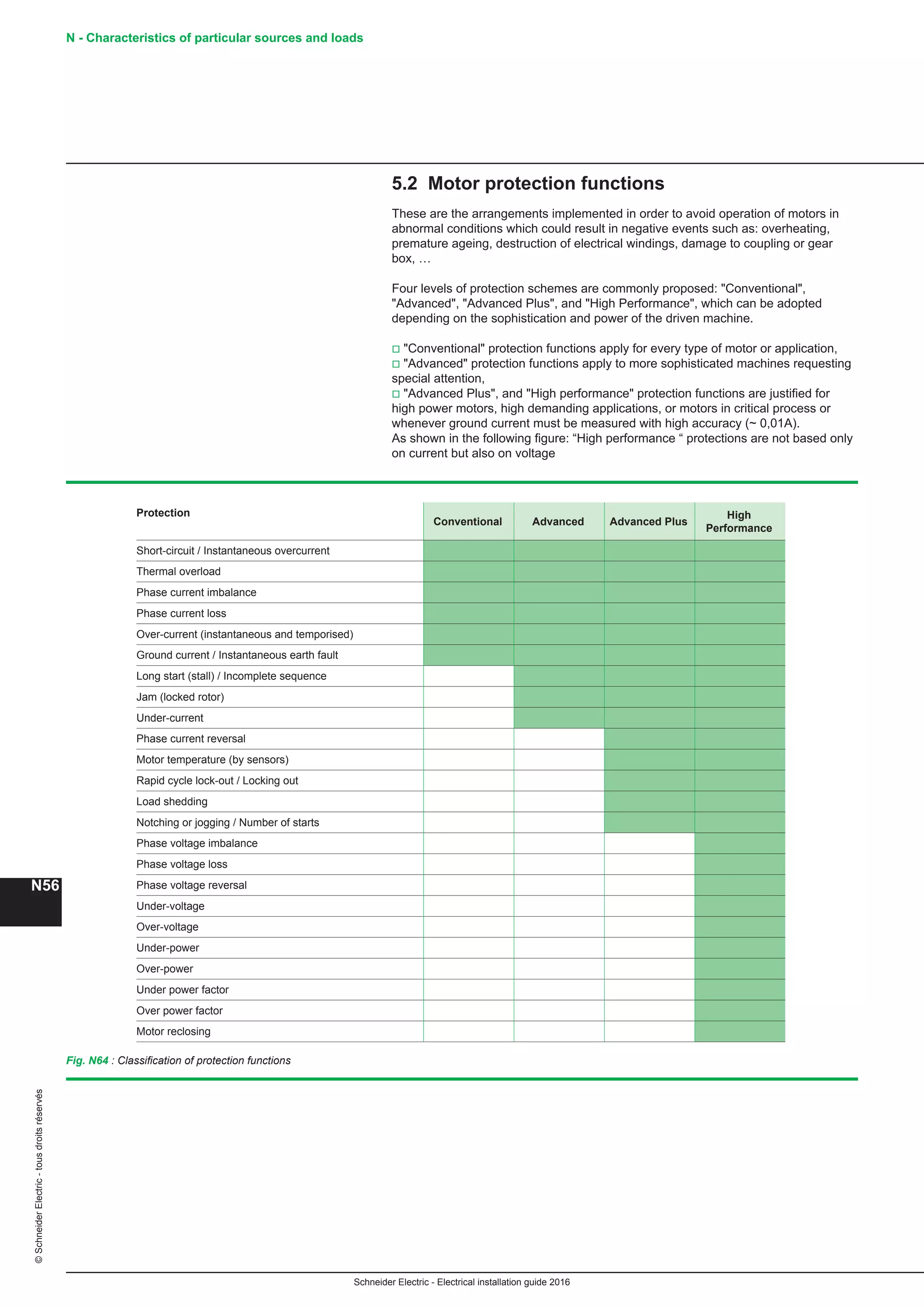
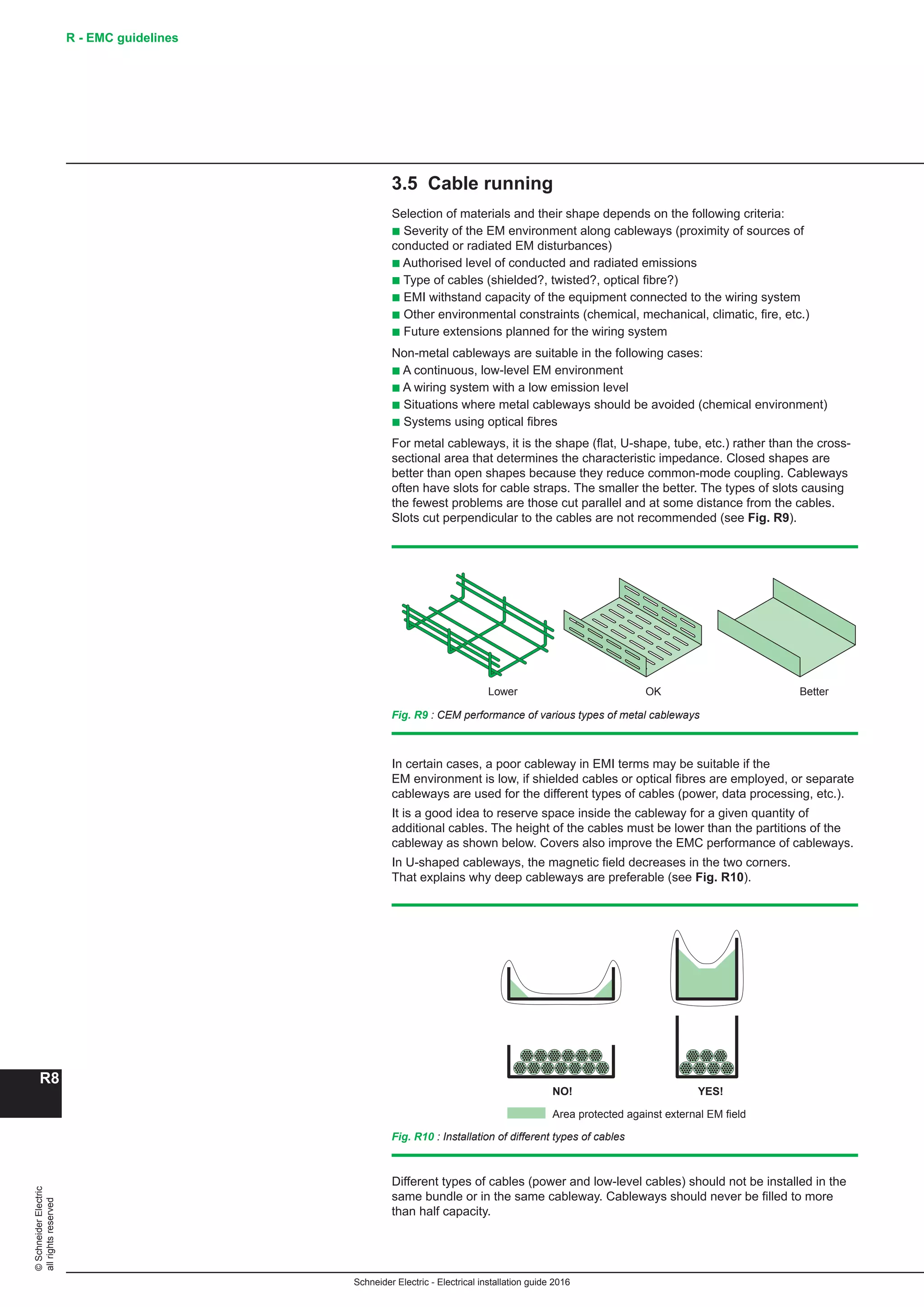
b The main LV switchboard - MLVS - (see Fig. E27a)
b Motor control centres - MCC - (see Fig. E27b)
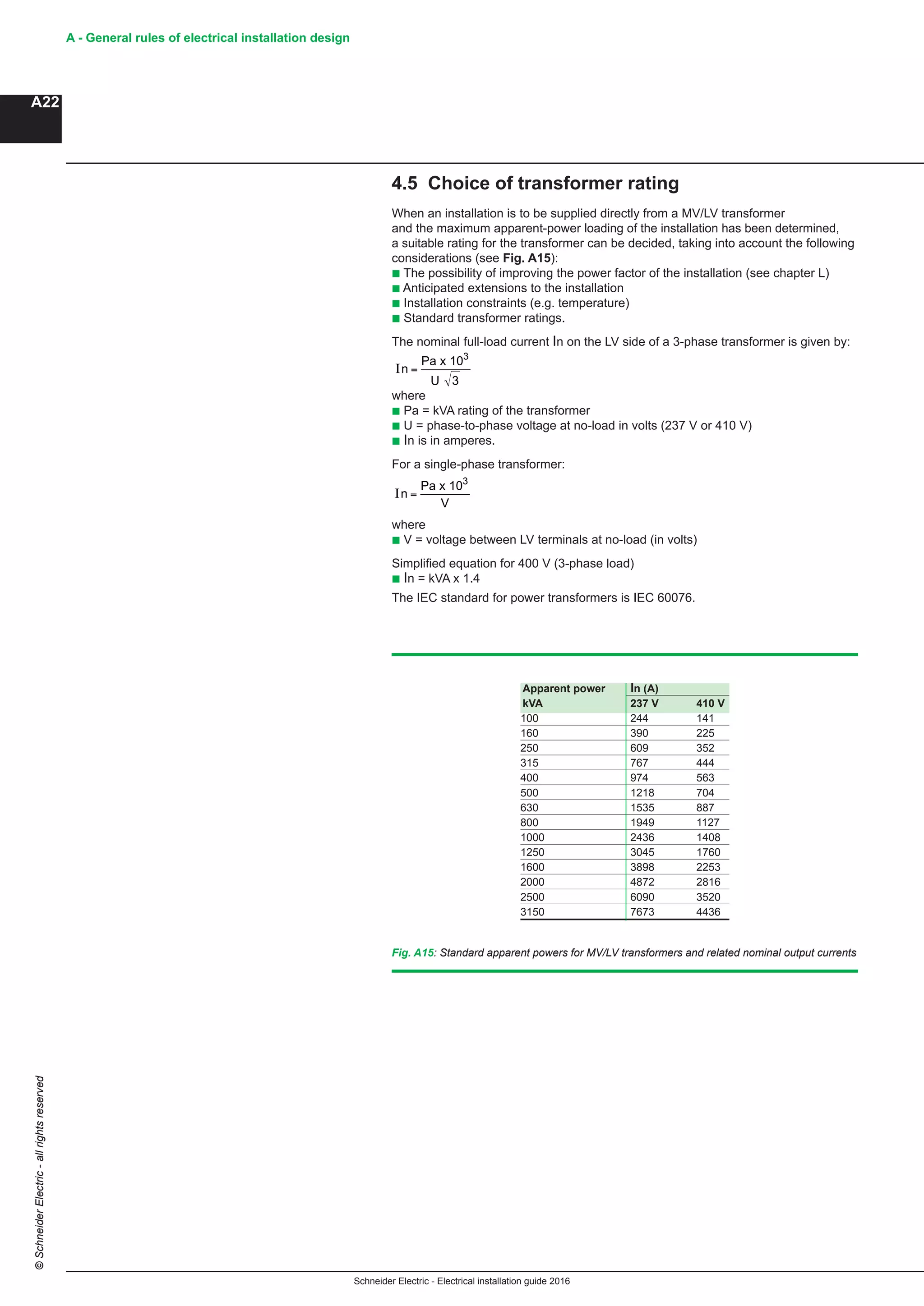
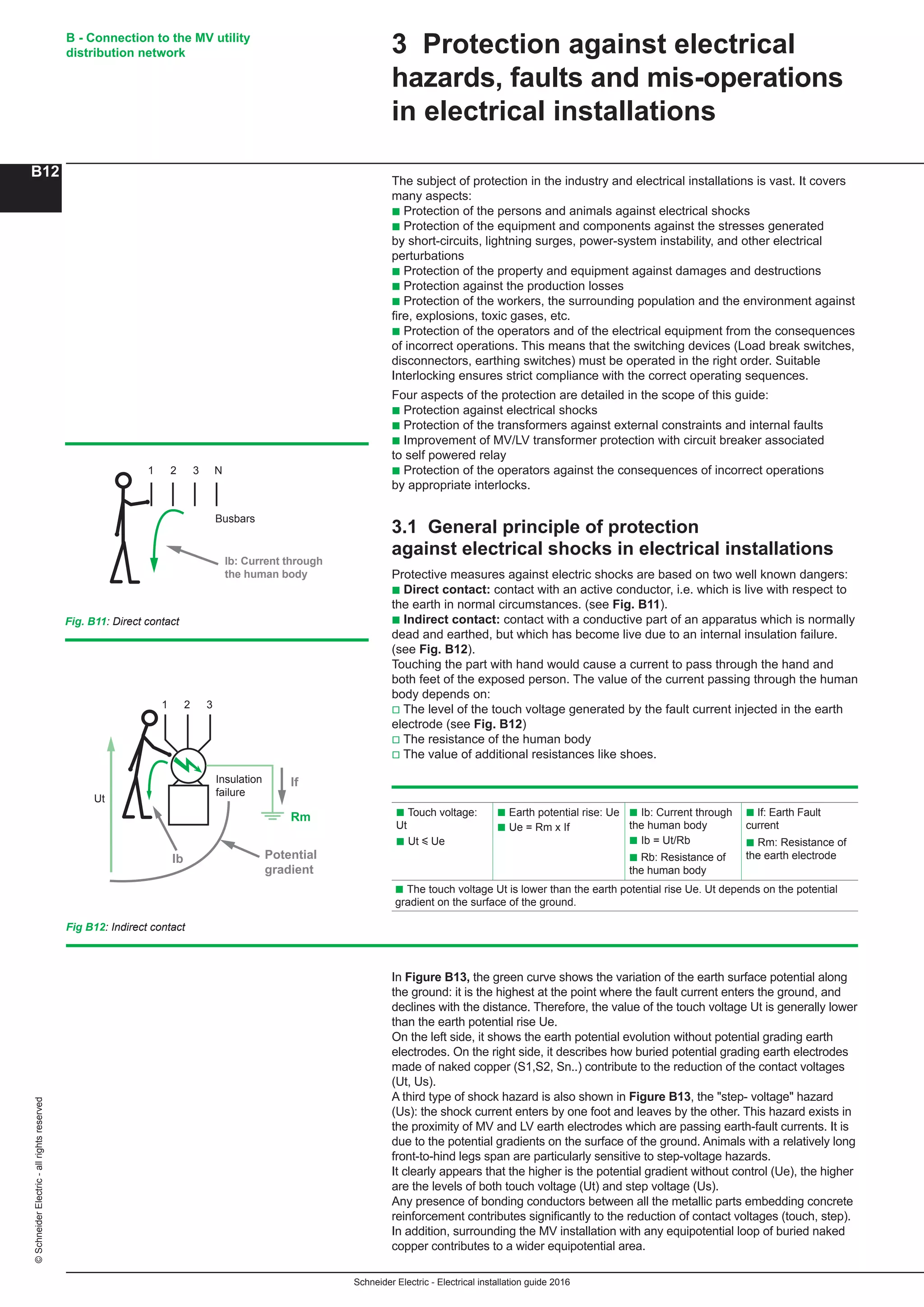
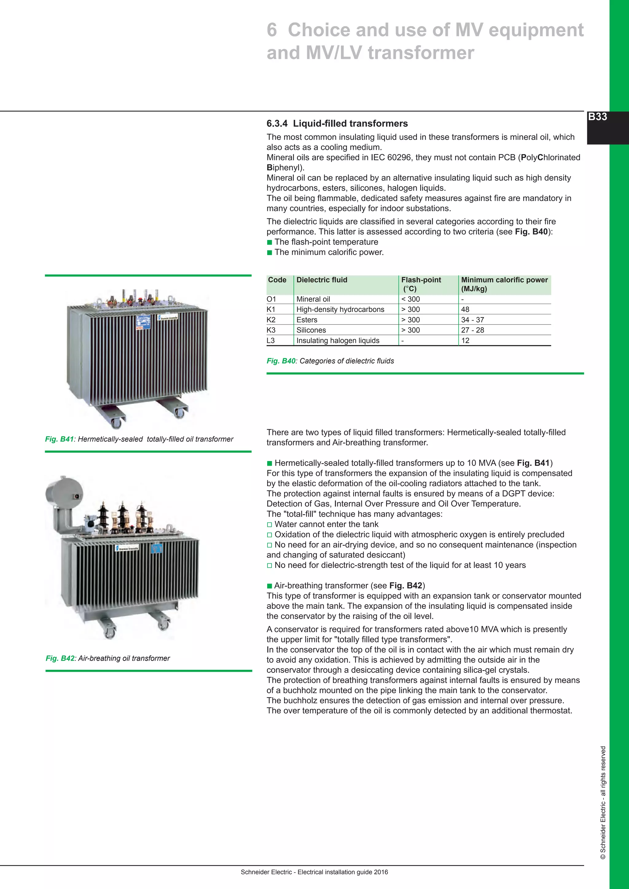
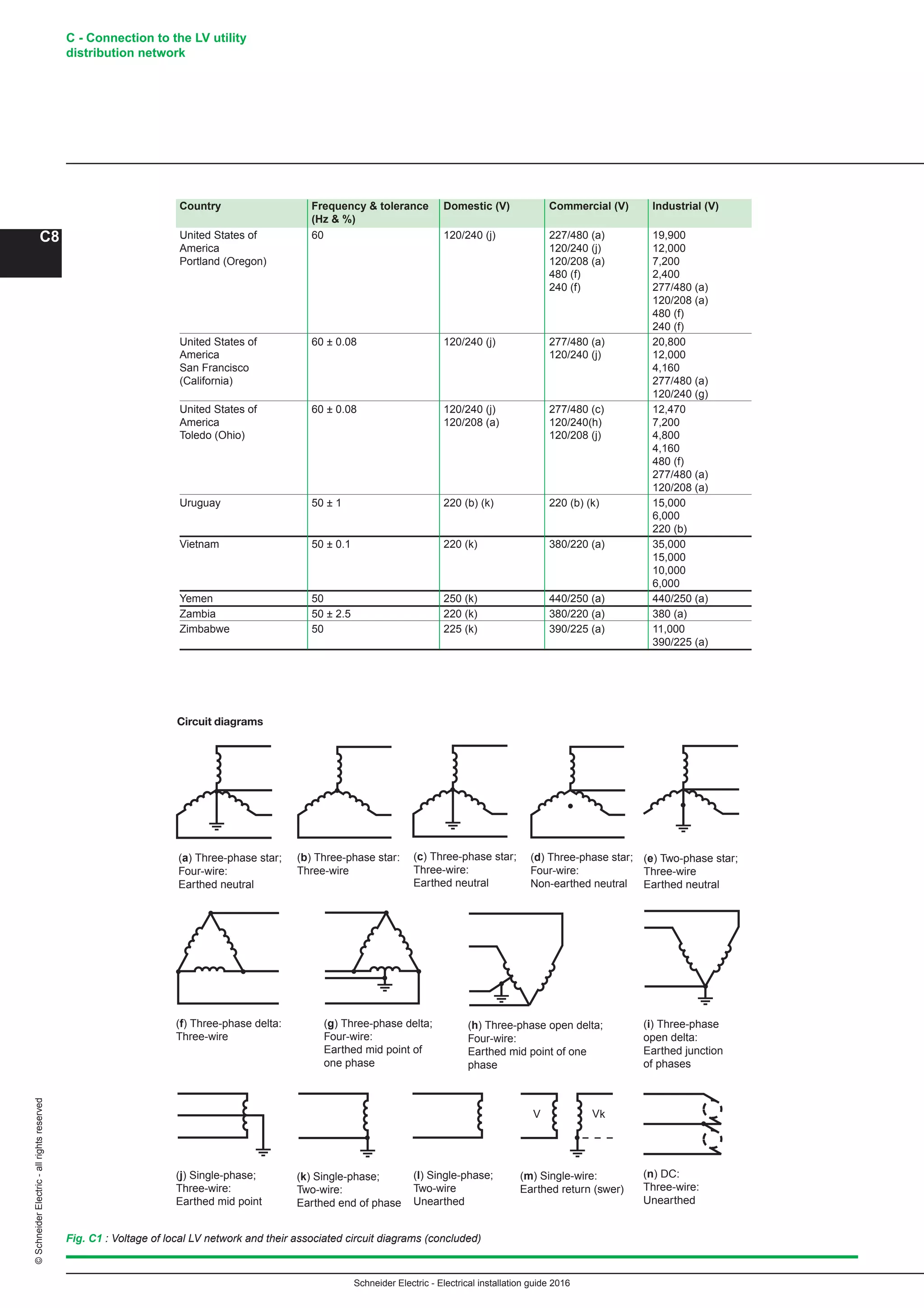
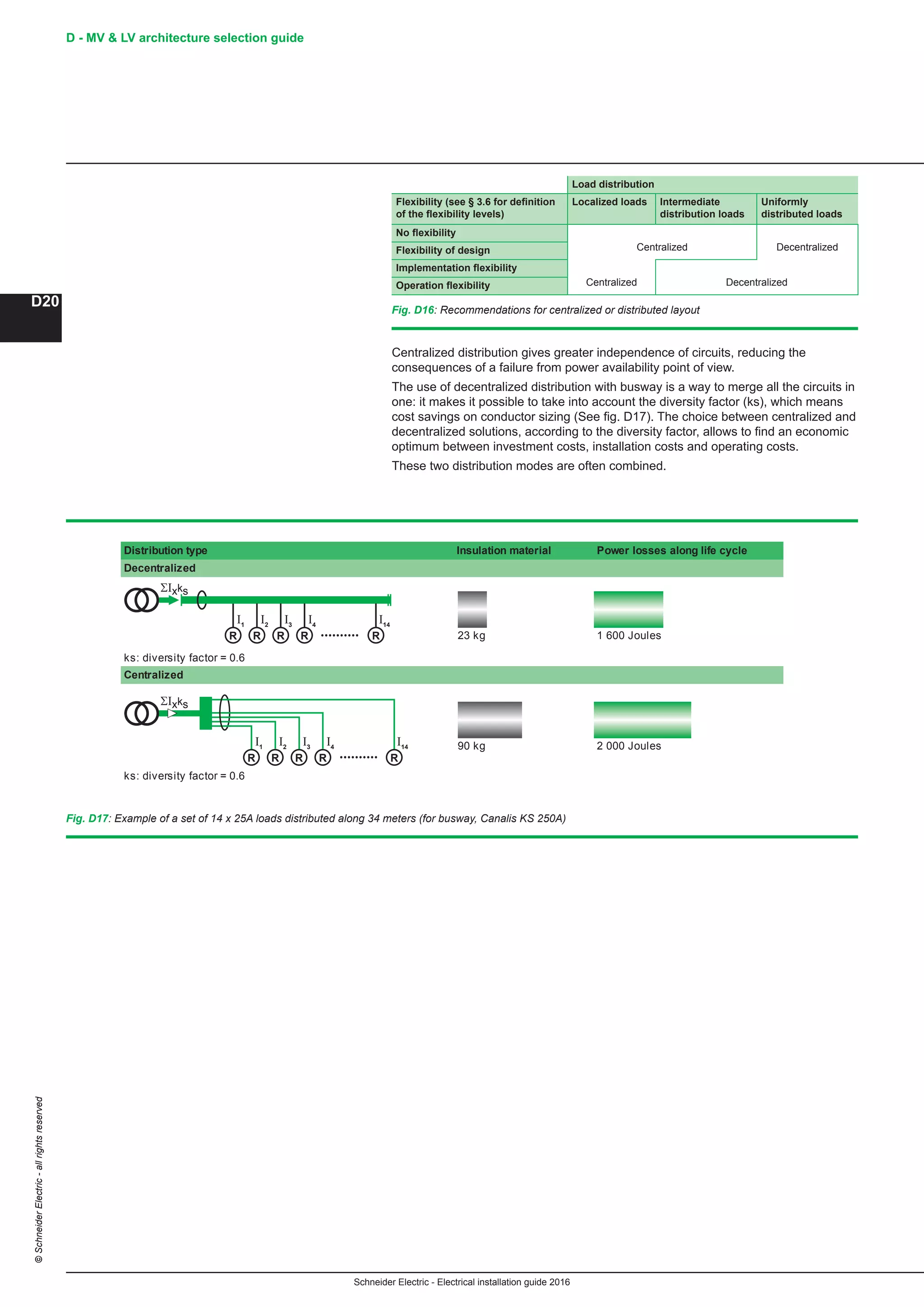
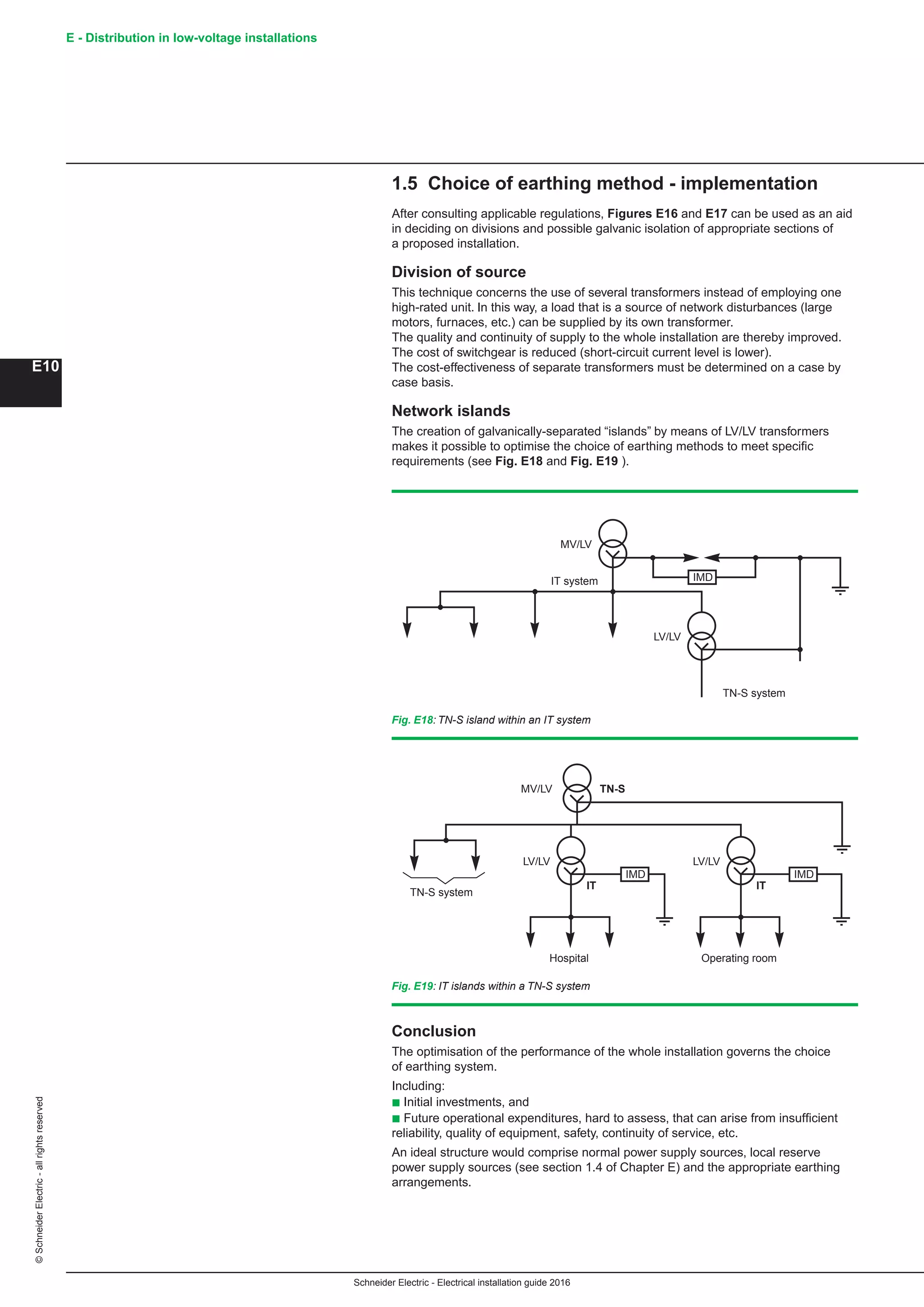
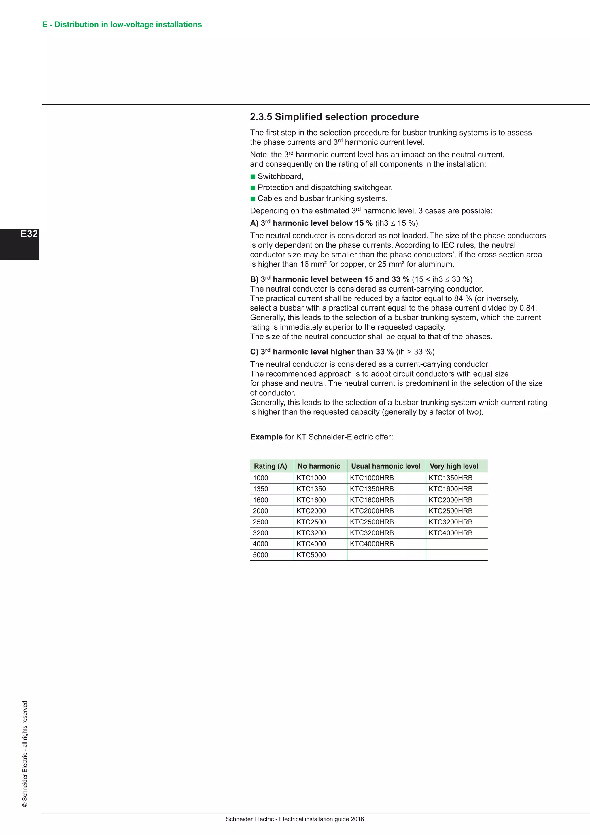
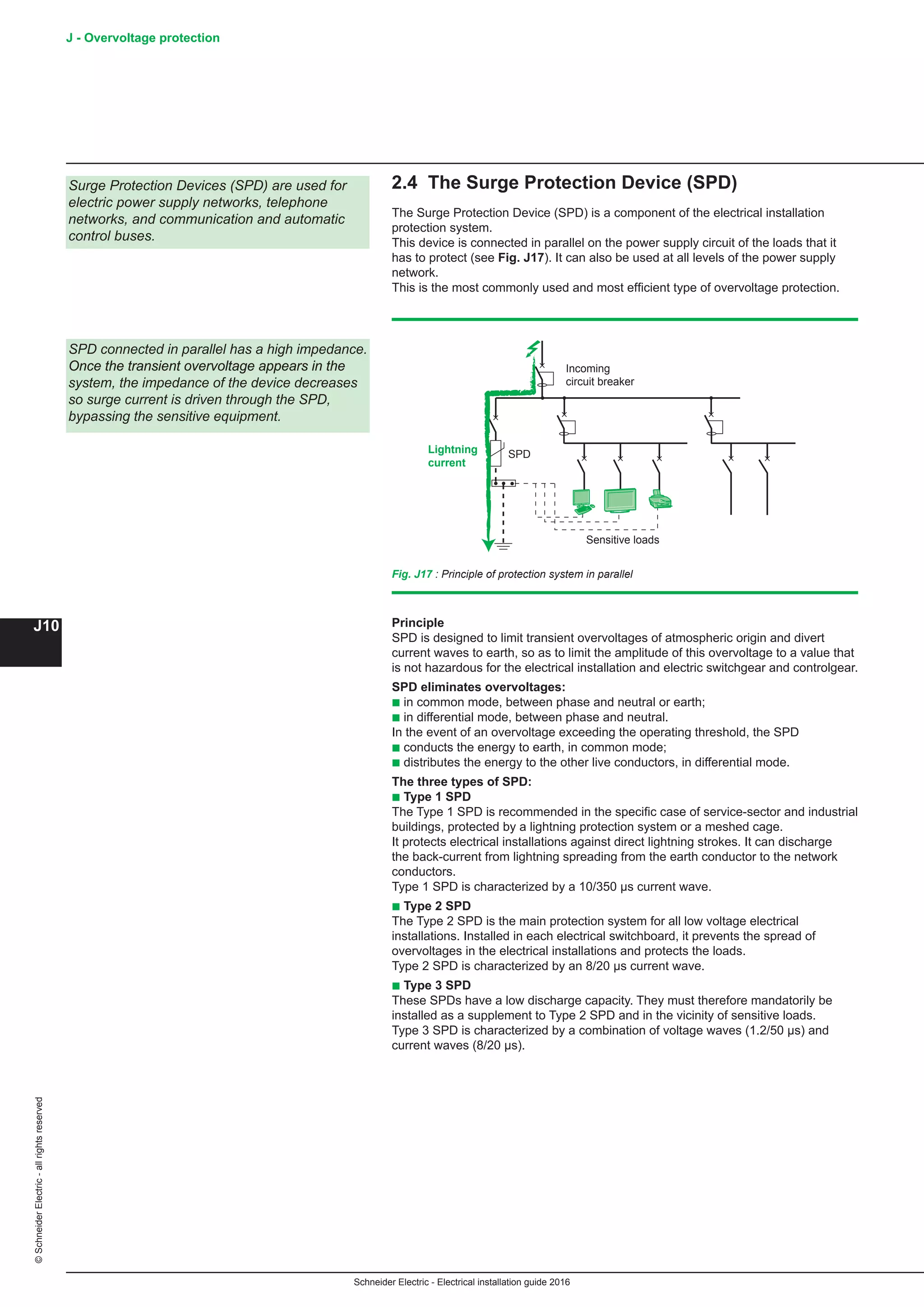
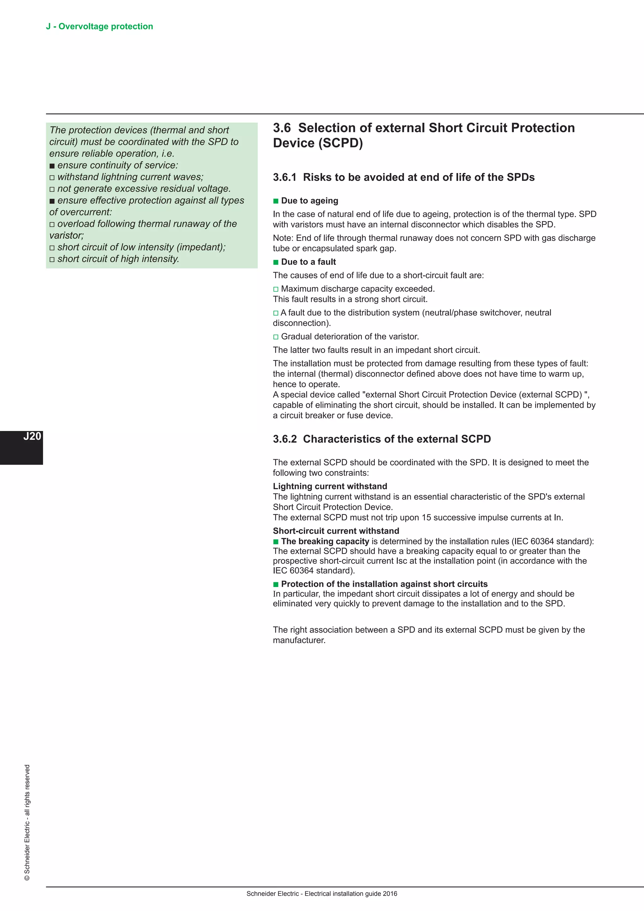
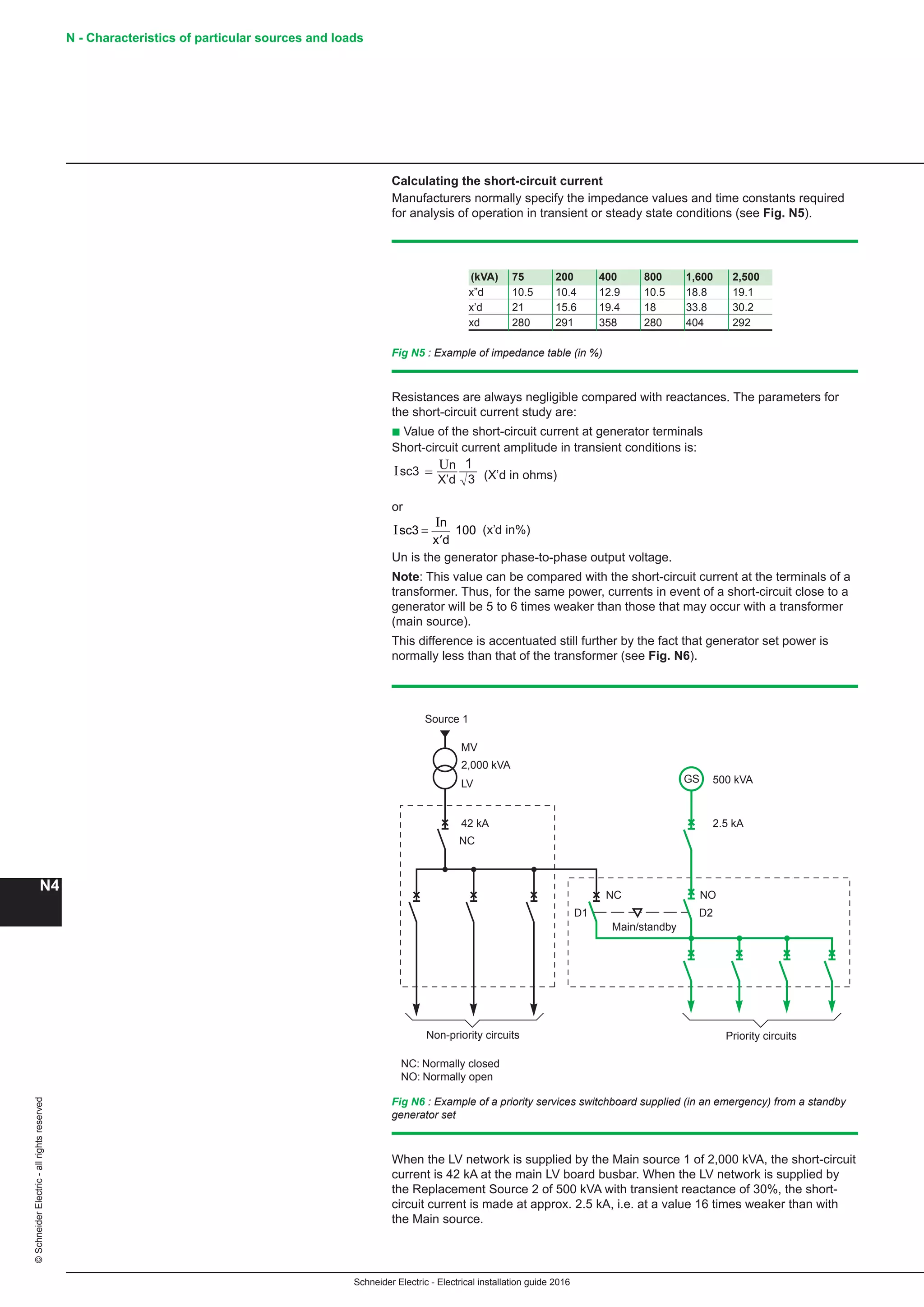
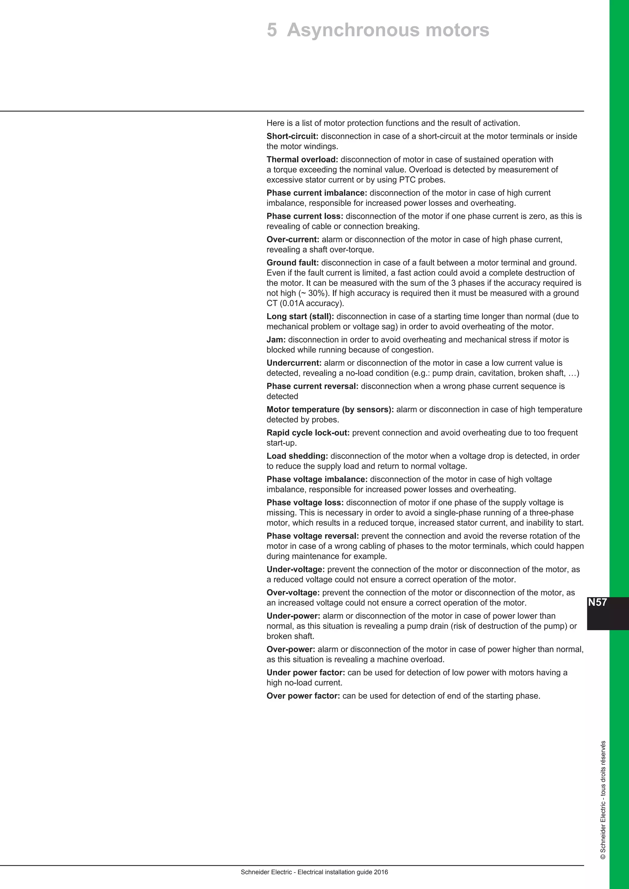
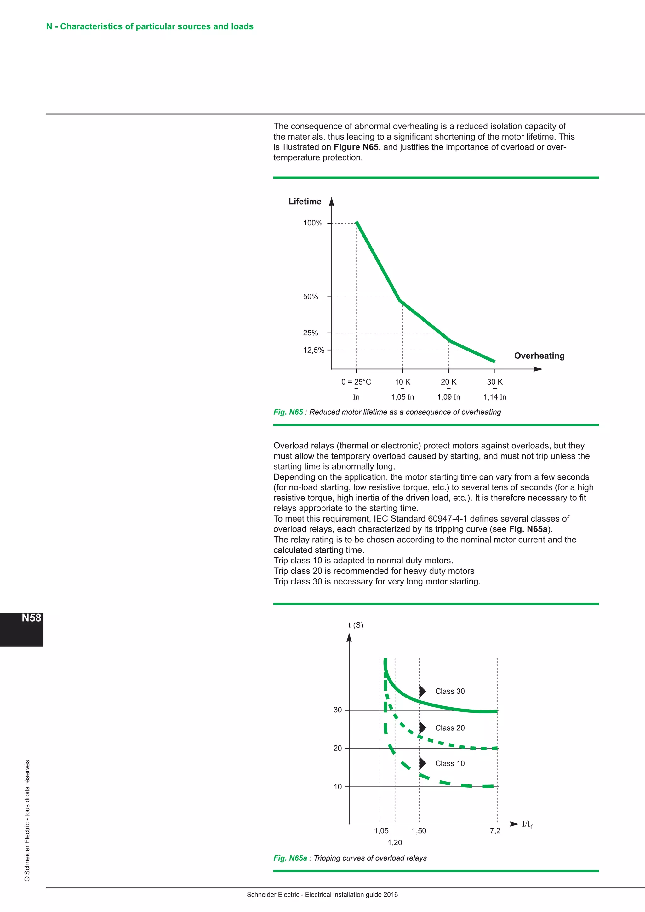
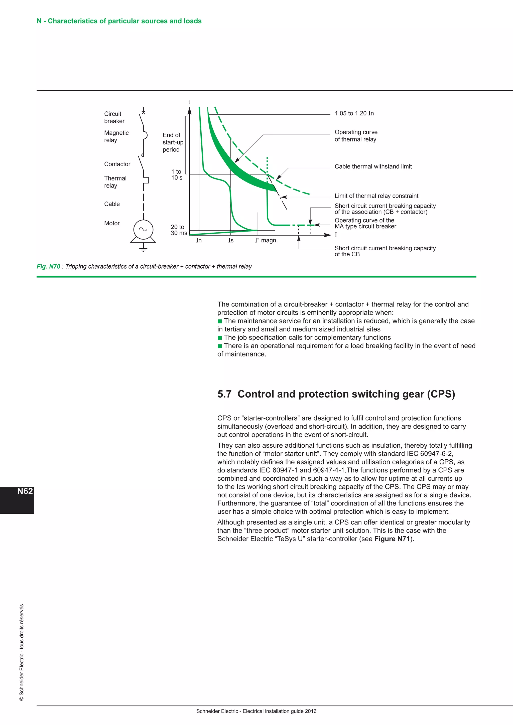
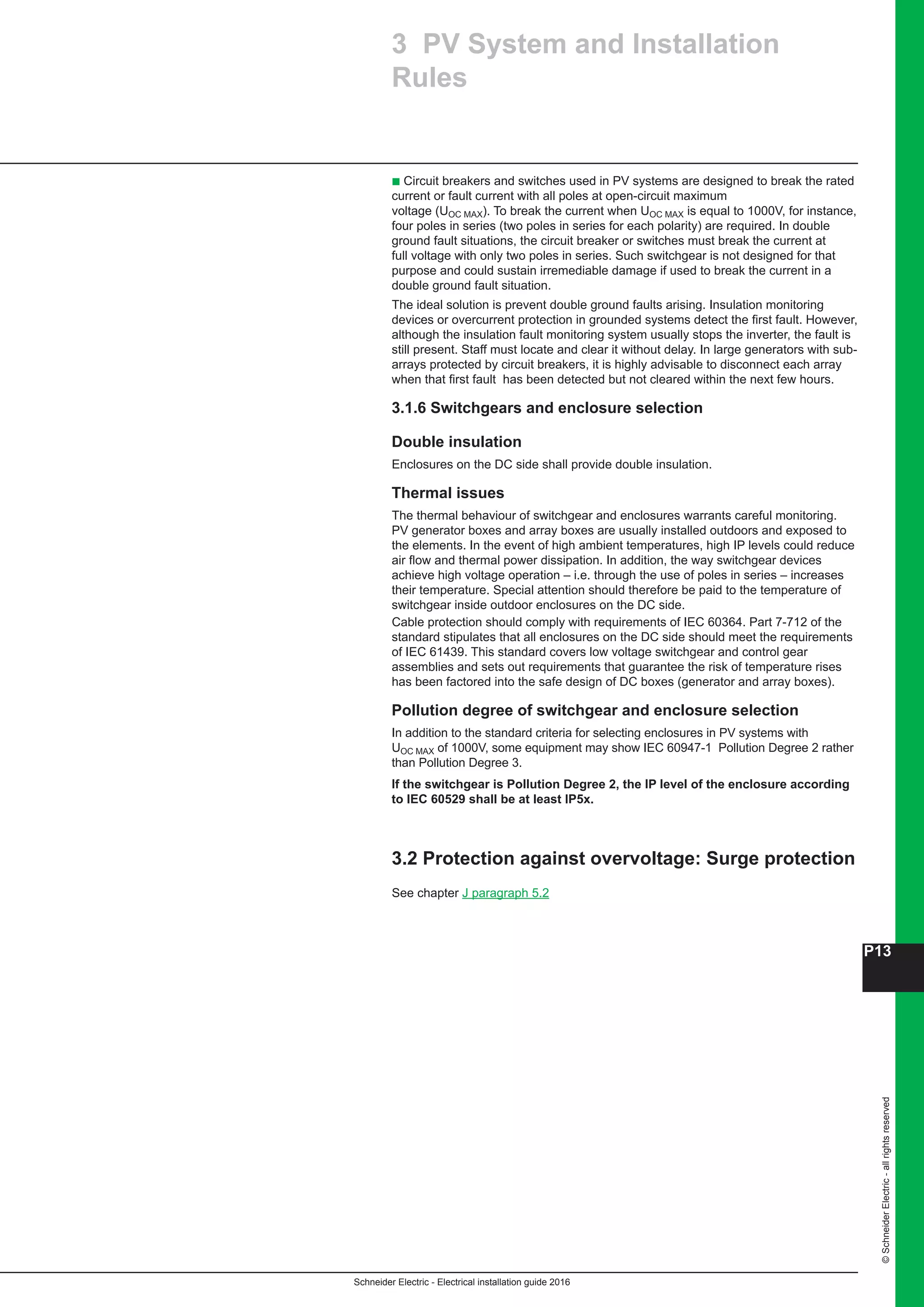
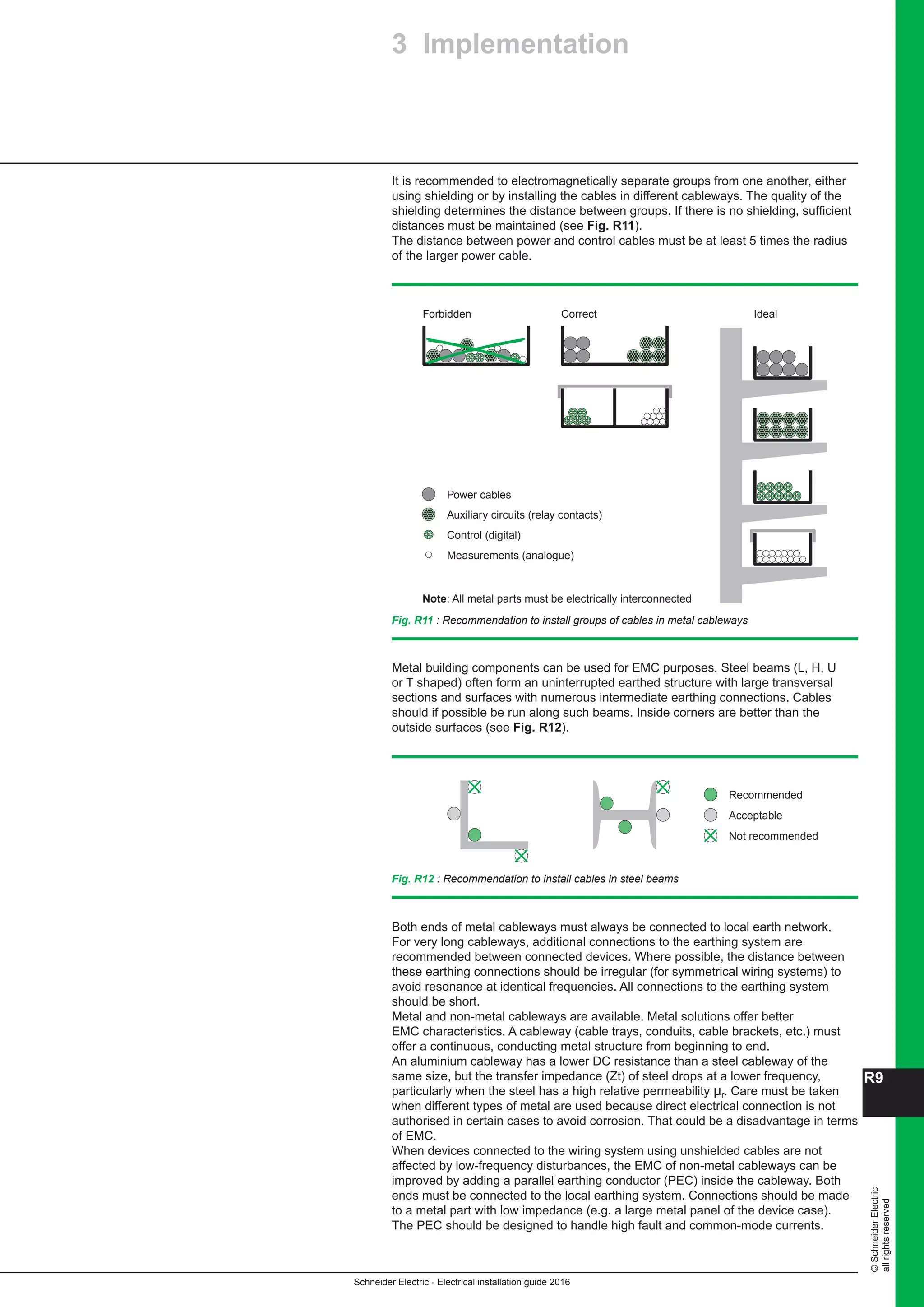
b Sub-distribution switchboards (see Fig. E28)
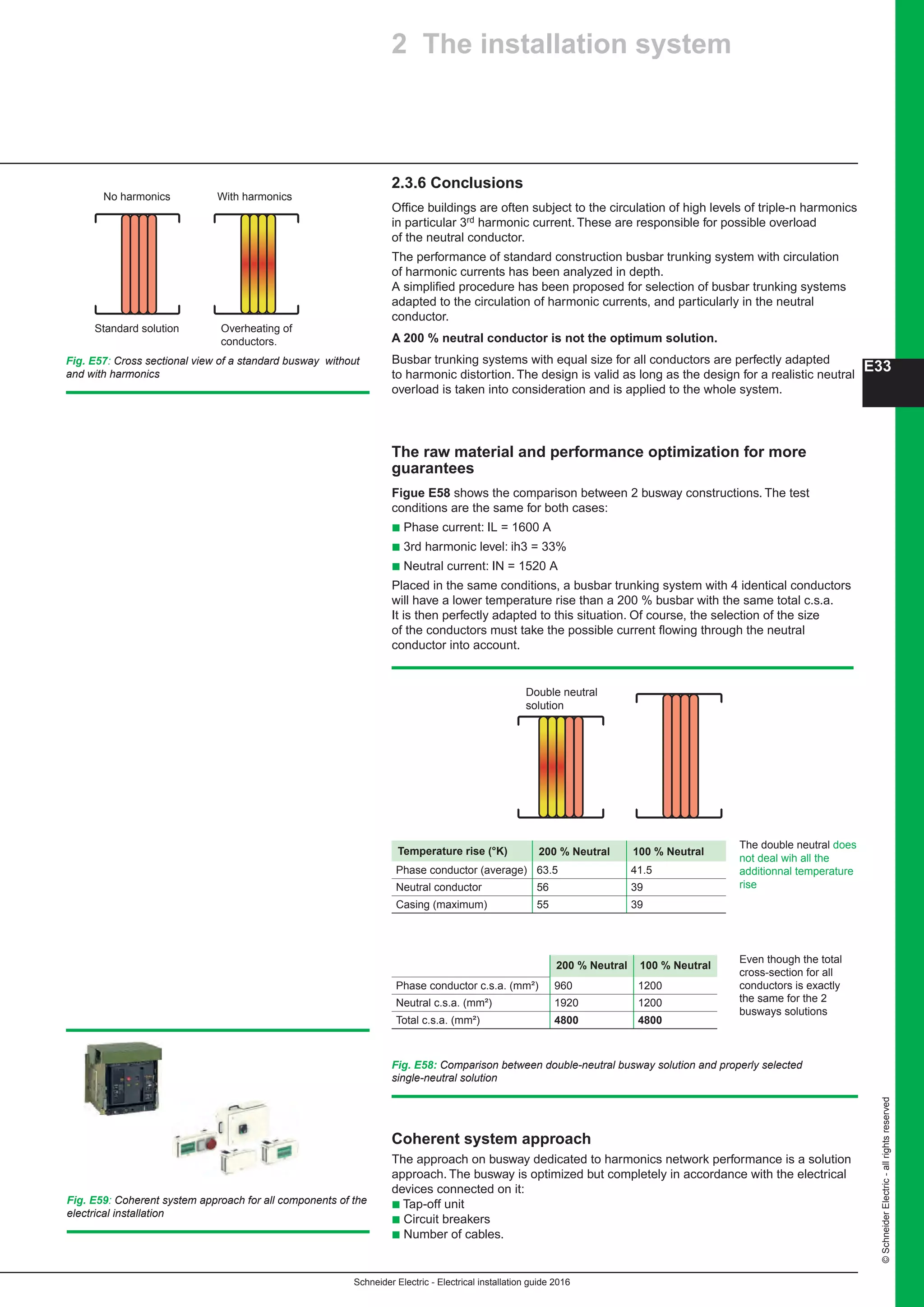
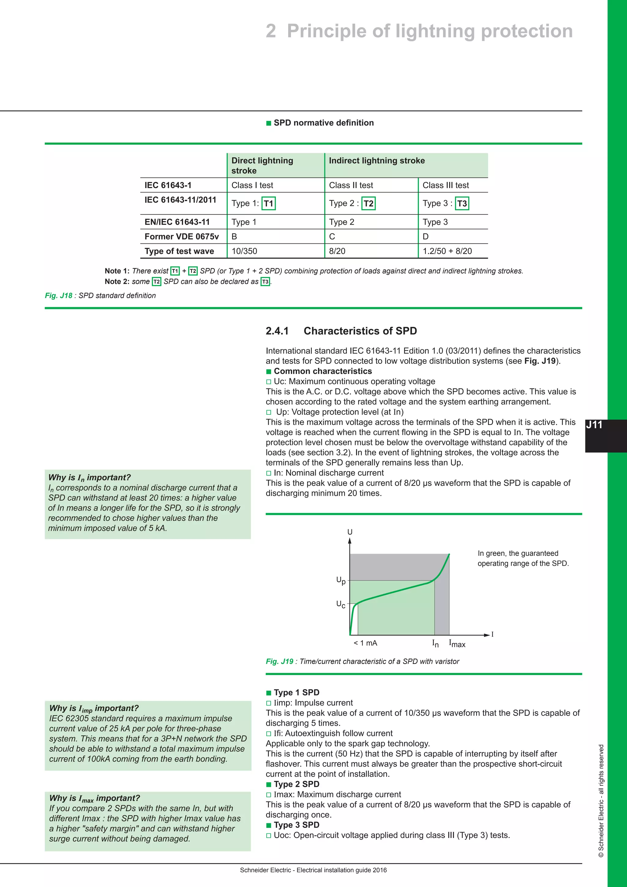
b Final distribution switchboards (see Fig. E29).
Distribution switchboards for specific applications (e.g. heating, lifts, industrial
processes) can be located:
b Adjacent to the main LV switchboard, or
b Near the application concerned.
Sub-distribution and final distribution switchboards are generally distributed
throughout the site.
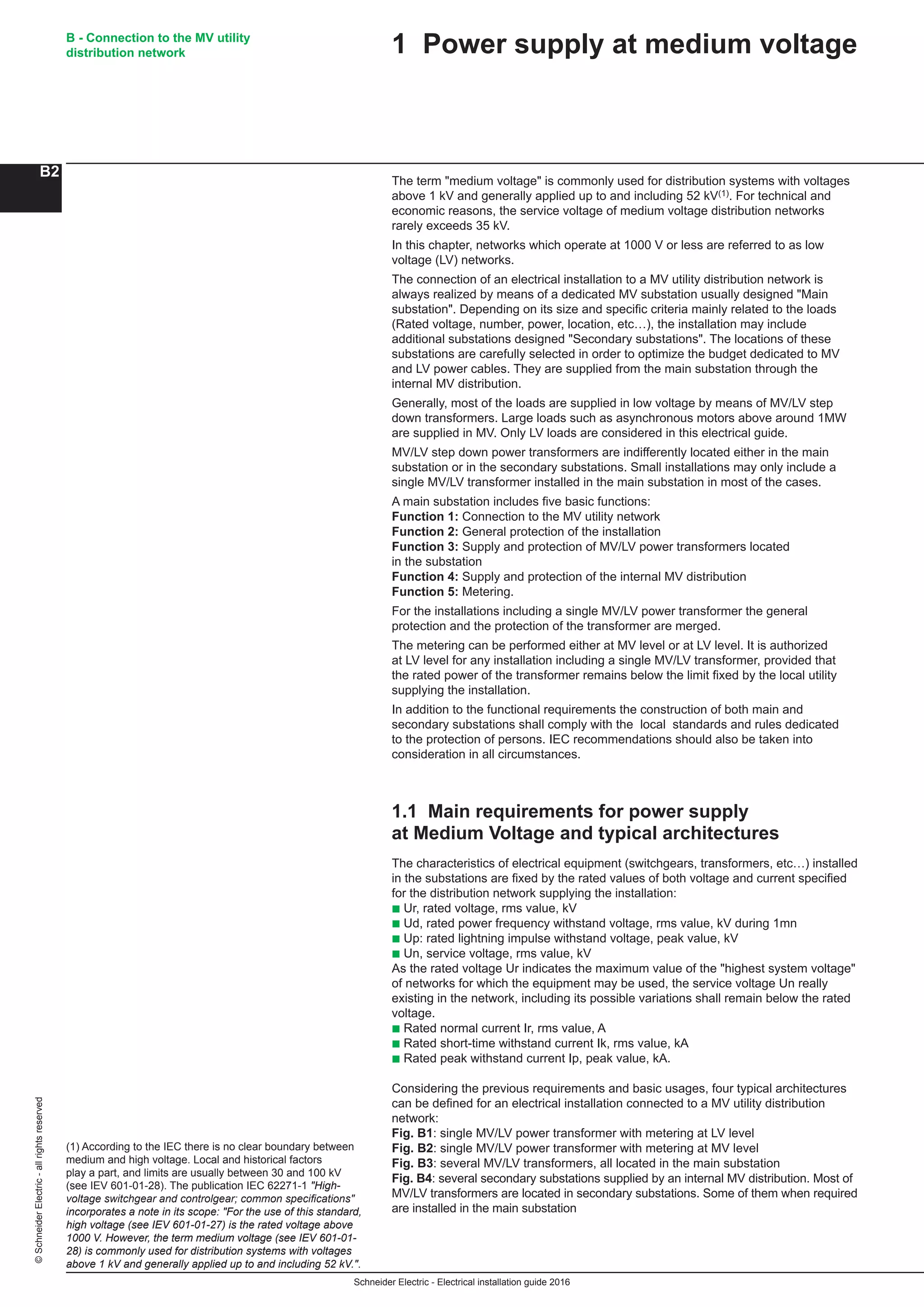
Distribution switchboards, including the main
LV switchboard (MLVS), are critical to the
dependability of an electrical installation.
They must comply with well-defined standards
governing the design and construction
of LV switchgear assemblies
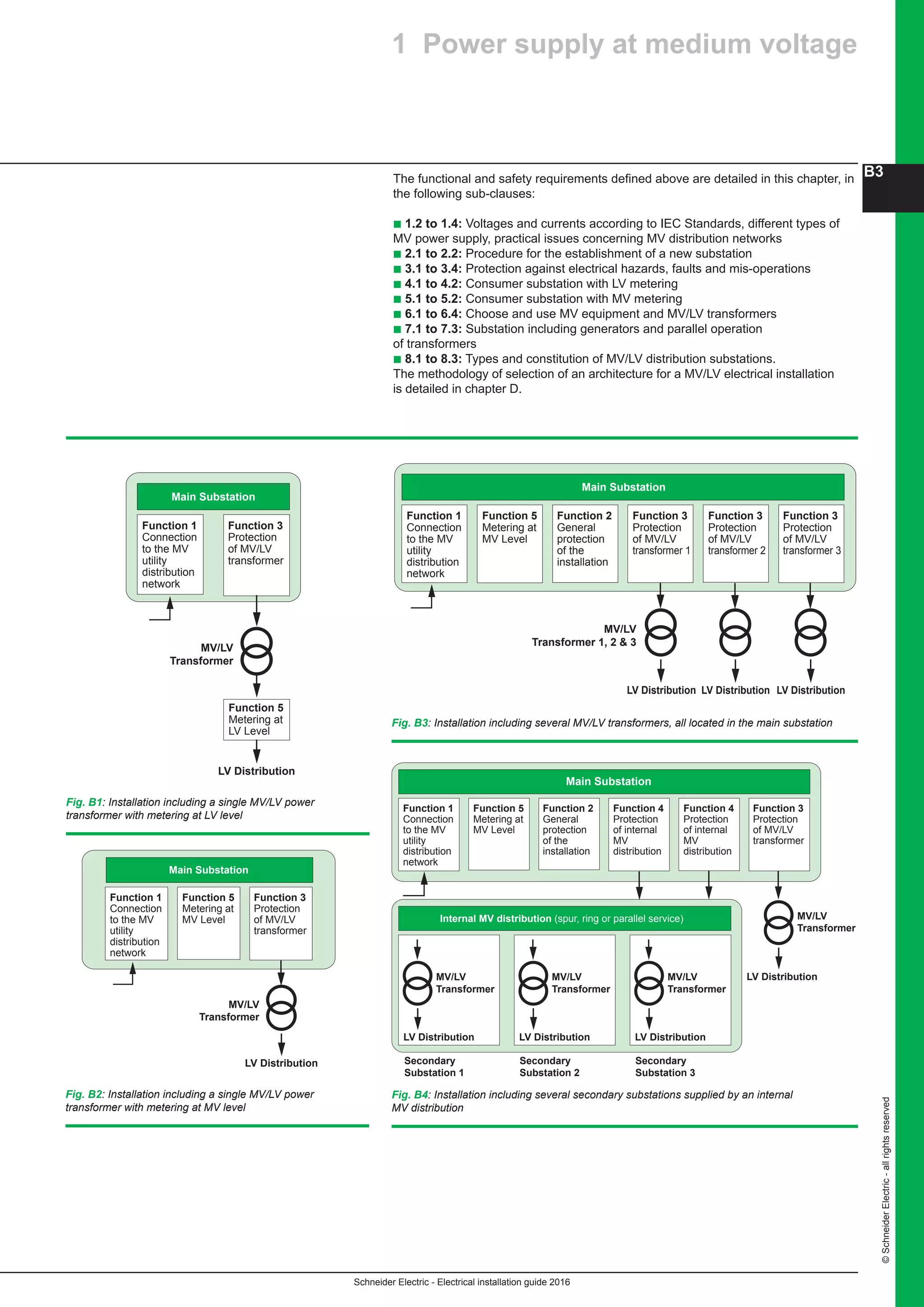
The load requirements dictate the type
of distribution switchboard to be installed
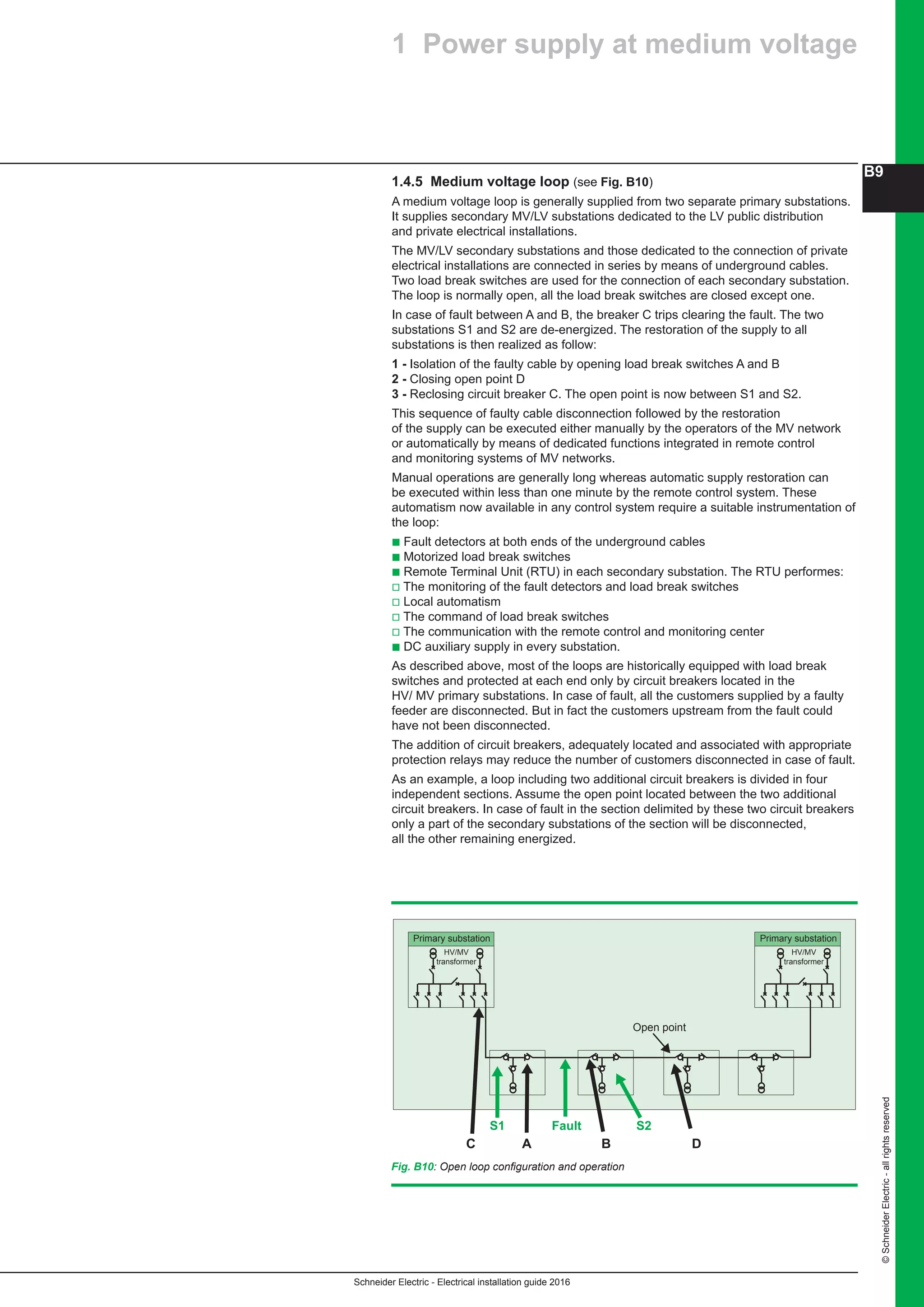
Fig. E27: [a] A main LV switchboard - MLVS - (Prisma Plus P) with incoming circuits in the form
of busways - [b] A LV motor control centre - MCC - (Okken)
Fig. E28: A sub-distribution switchboard (Prisma Plus G) Fig. E29: Final distribution switchboards [a] Prisma Plus G Pack; [b] Kaedra; [c] mini-Pragma
a b c
a b](https://image.slidesharecdn.com/10electrical-installation-guide-2016-160721063350/75/10-electrical-installation-guide-2016-147-2048.jpg)


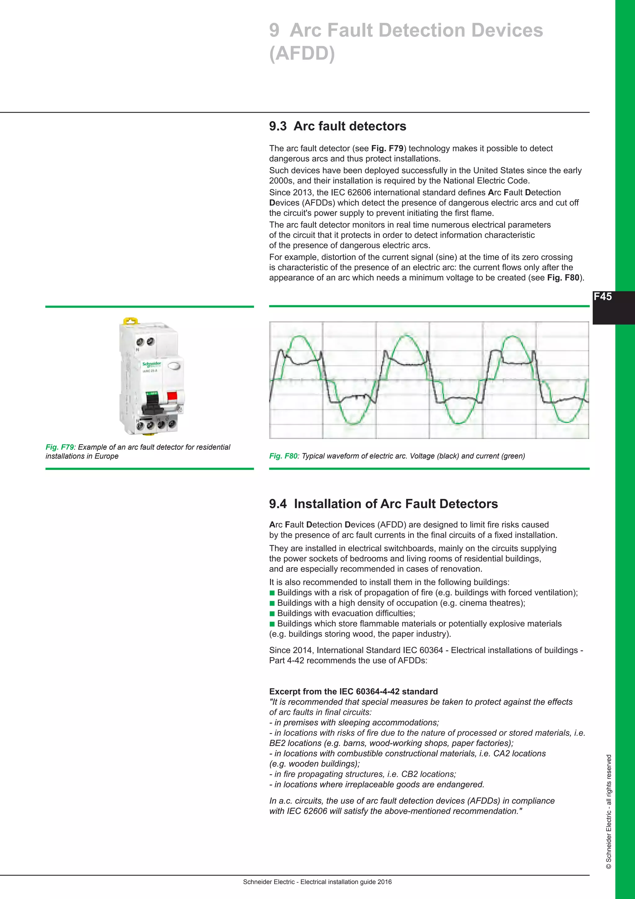


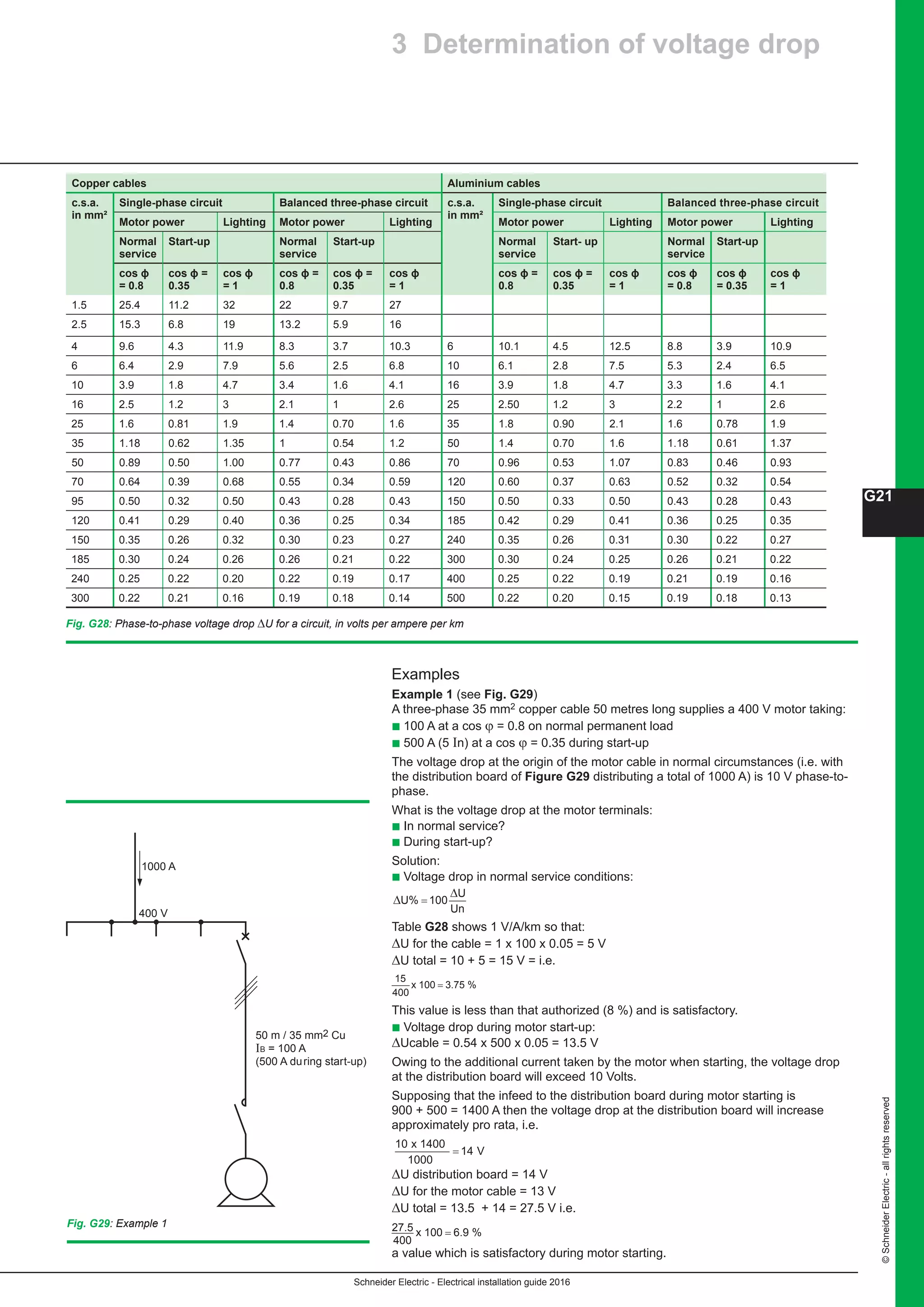
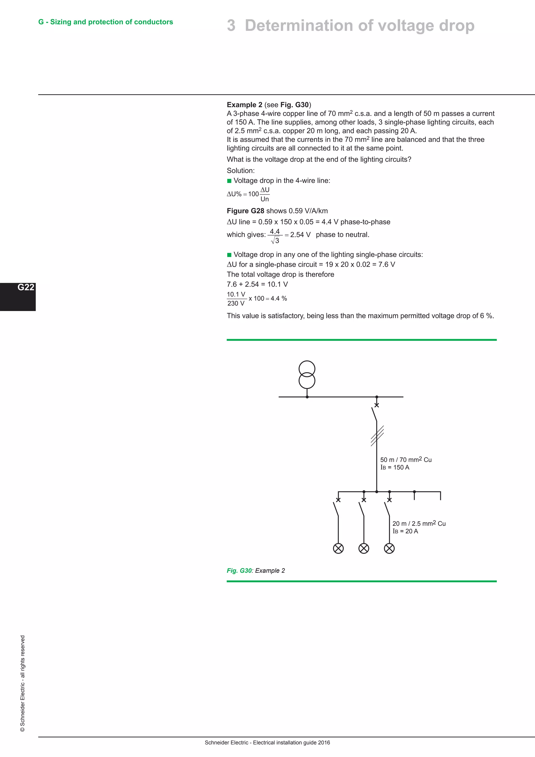
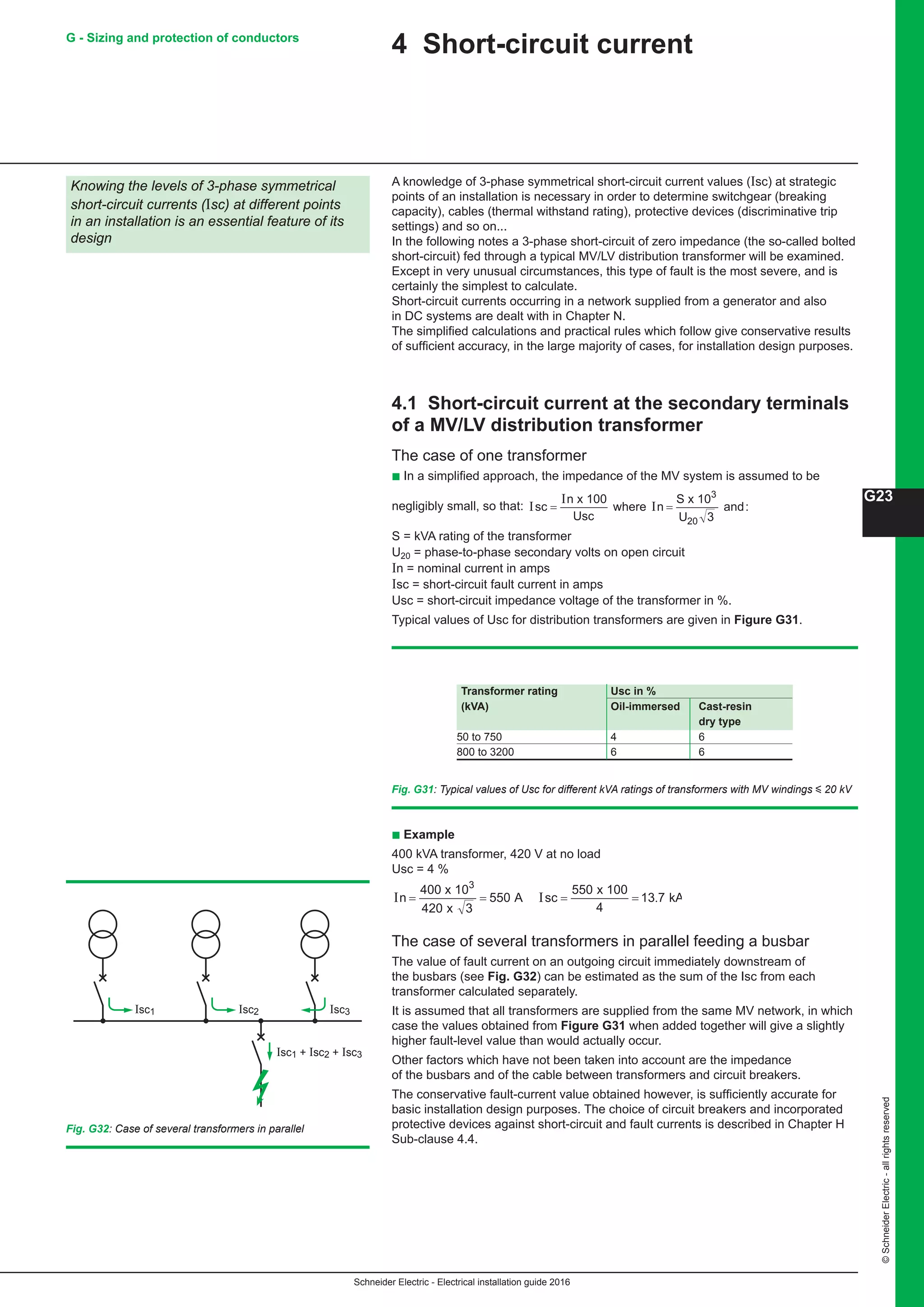
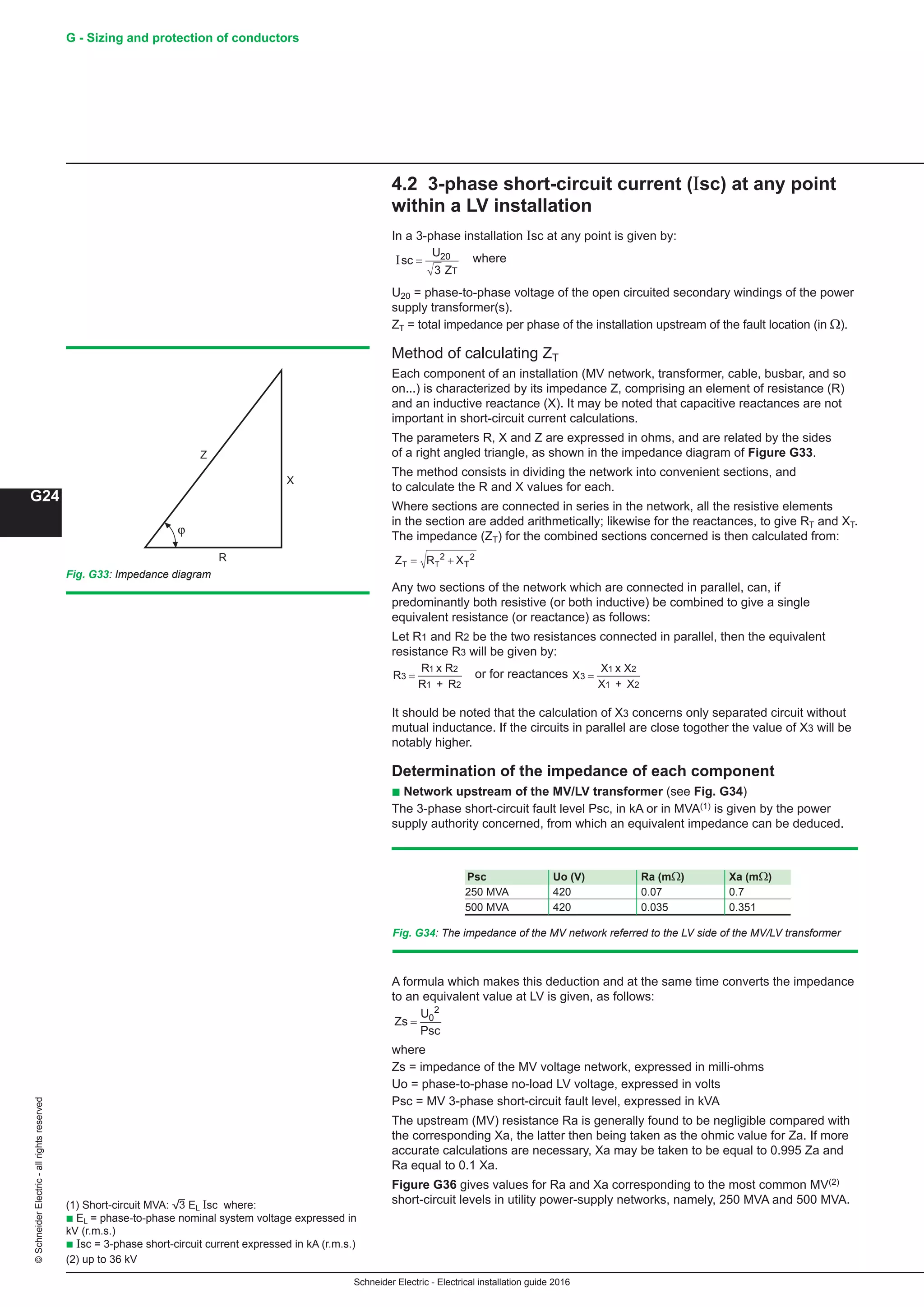
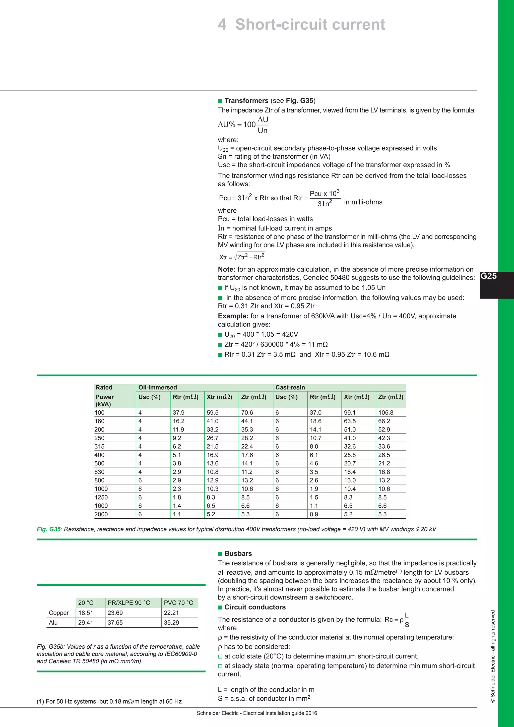
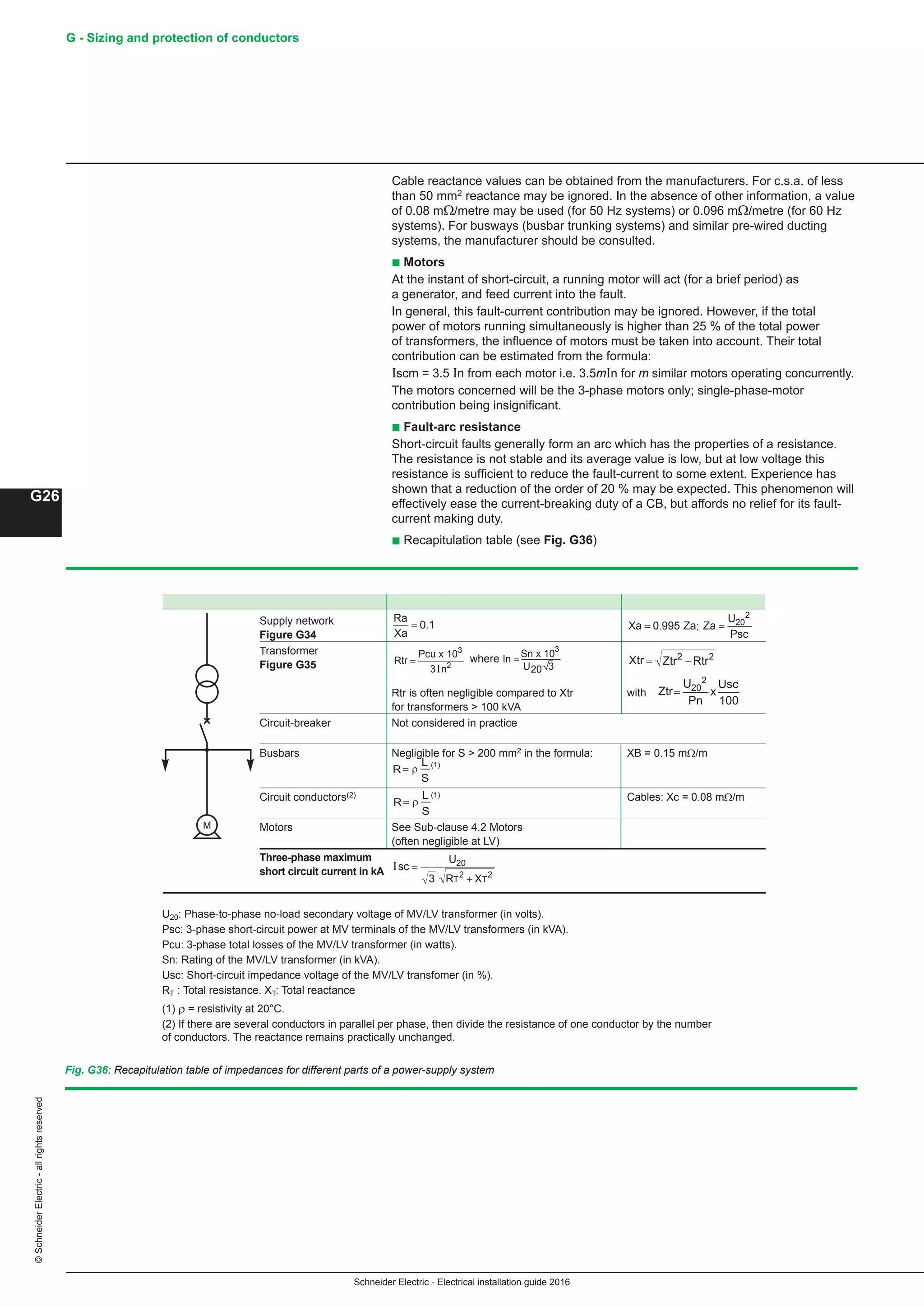

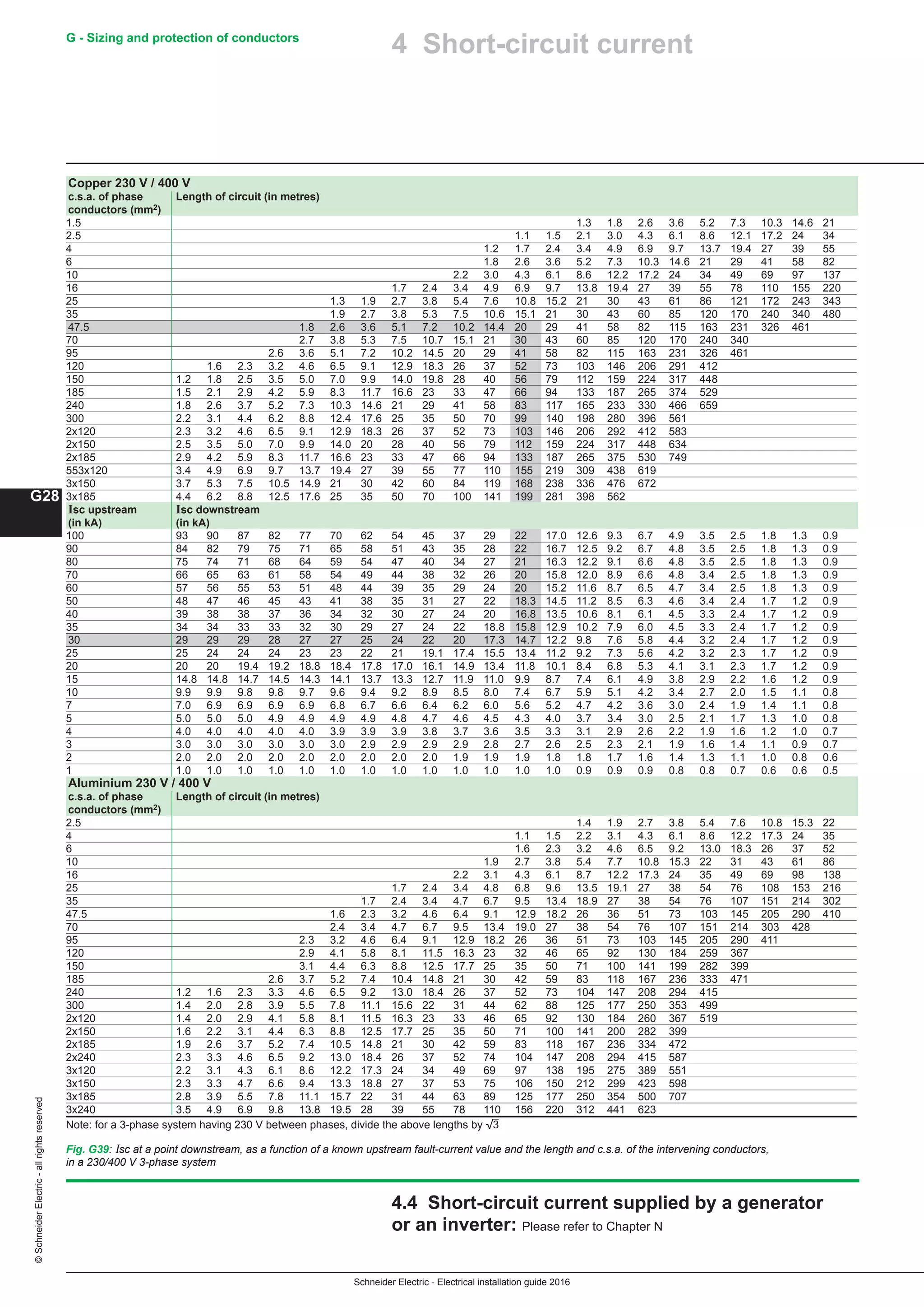
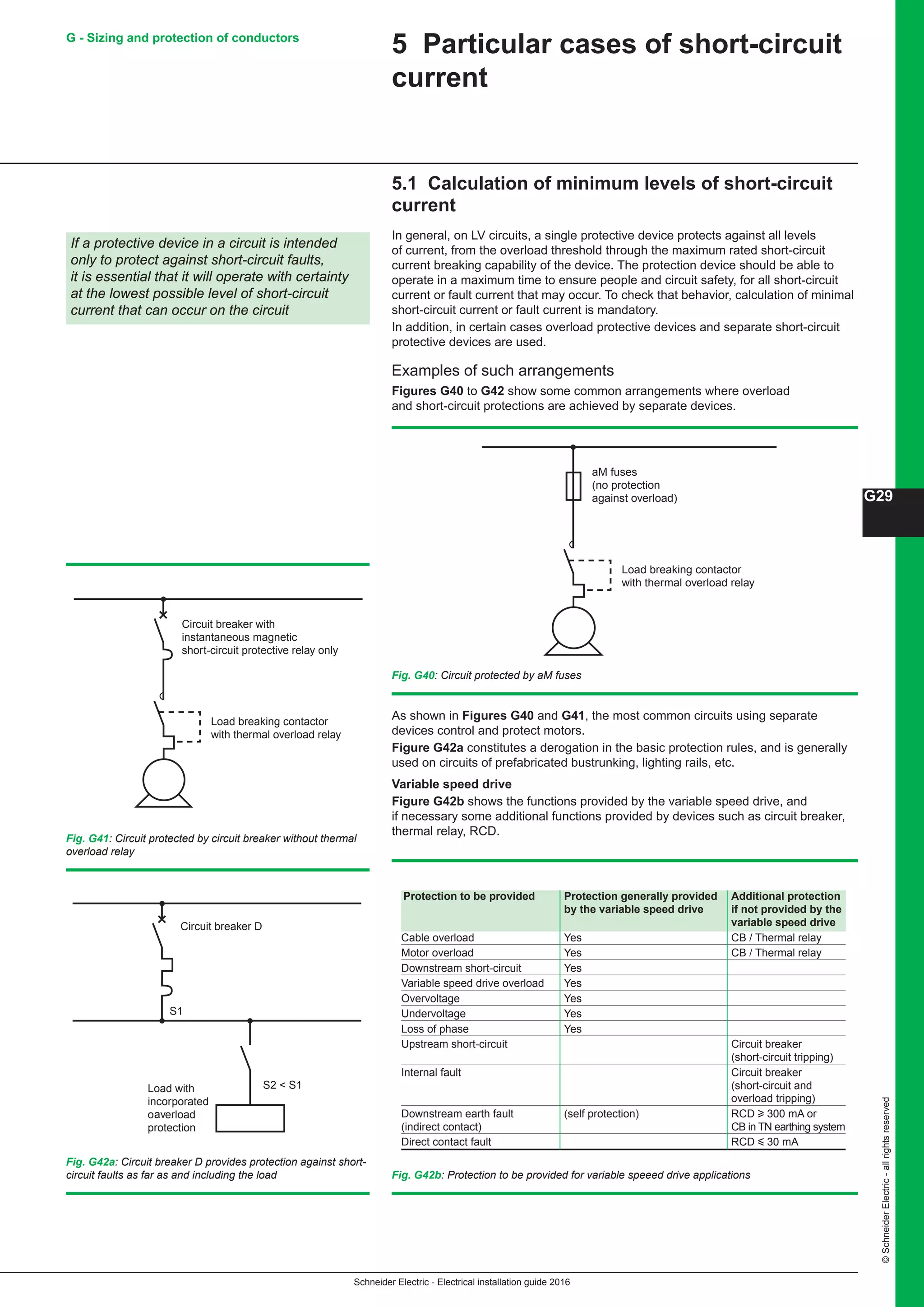


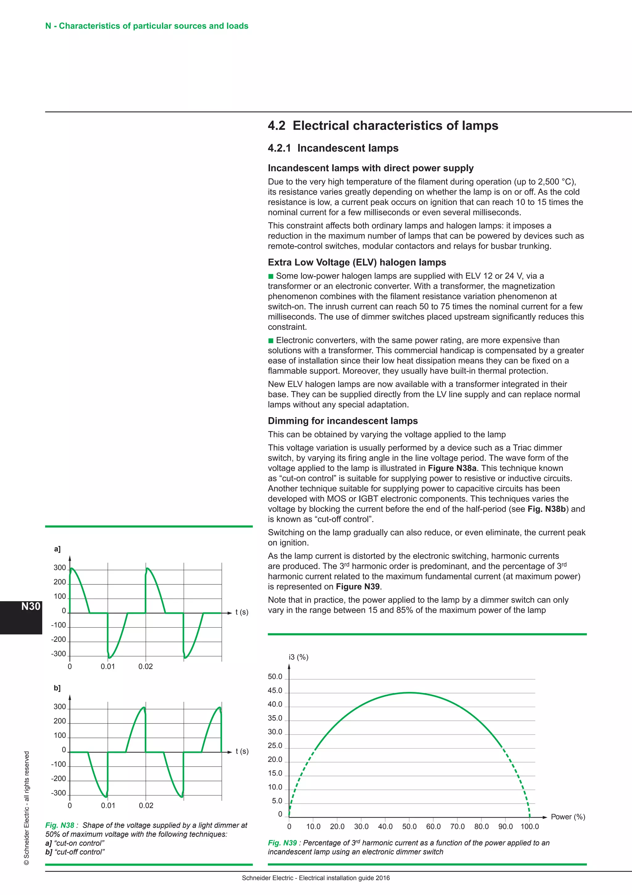


The Electrical Installation Guide 2016 is designed for electrical professionals, providing guidelines for low-voltage electrical installations in compliance with IEC standards, specifically IEC 60364. This comprehensive document addresses design, selection, installation, and maintenance of electrical systems while ensuring safety and operational functionality. It also serves as a reference rather than a ready-to-use handbook, emphasizing the importance of adhering to original international and local standards.


