Downloaded 144 times


![Switchgear and Substations
3.3 Low-Voltage Switchgear
3
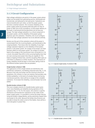
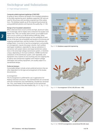
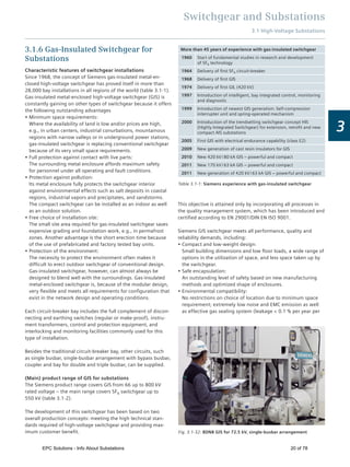
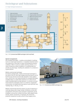
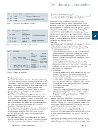
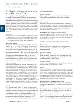
Double-front installations
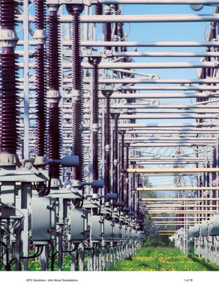
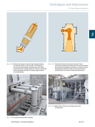
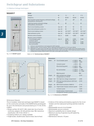
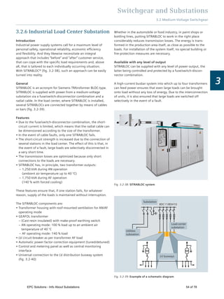
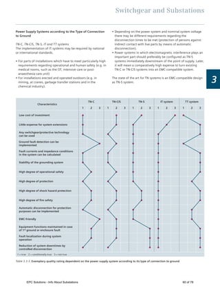
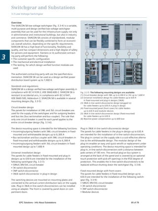
In the double-front installation, the panels are positioned in a
row next to and behind one another. The main advantage of a
double-front installation is the extremely economic design
through the supply of the branch circuits on both operating
panels from one main busbar system.
The "double-front unit" system structure is required for the
assignment of certain modules.
A double-front unit (fig. 3.3-14) consists of at least 2 and a
maximum of 4 panels. The width of the double-front unit is
determined by the widest panel (1) within the double-front unit.
This panel can be placed on the front or rear side of the double-
front unit. Up to three panels (2), (3), (4) can be placed on the
opposite side. The sum of the panel widths (2) to (4) must be
equal to the width of the widest panel (1). The panel combina-
tion within the double-front unit is possible for all technical
installations with the following exceptions.
Exceptions
The following panels determine the width of the double-front
unit and may only be combined with an empty panel.
Bus sectionalizer unit
5,000 A incoming / outgoing feeder
6,300 A incoming / outgoing feeder
Weights
The panel weights as listed in table 3.3-5 should be used for the
transportation and dimensioning of building structures such as
cable basements and false floors.
Fig. 3.3-14: Panel arrangement of double-front installations
(1)
(3)(2) (4)
Double-front units
Double-front installations – top view
Double-front installations only with main busbar system at the rear
Environmental conditions for switchgear
The climate and other external conditions (natural foreign
substances, chemically active pollutants, small animals) may
affect the switchgear to a varying extent. The effect depends on
the heating / air-conditioning systems of the switchgear room. If
higher concentrations are present, pollutant-reducing measures
are required, for example:
Air-intake for operating room from a less contaminated point
Slightly pressurizing the operating room (e.g. by blowing
uncontaminated air into the switchgear)
Switchgear room air conditioning (temperature reduction,
relative humidity < 60 %, if necessary, use air filters)
Reduction of temperature rise (oversizing of switchgear or
components such as busbars and distribution bars)
Power losses
The power losses listed in table 3.3-5 are approximate values for
a panel with the main circuit of functional units to determine the
power loss to be discharged from the switchgear room.
Table 3.3-5: Average weights of the panels including busbar (without cable)
Rated current [A]
Size
Minimum panel width
[mm]
Approx. weight
[kg]
Circuit-breaker design with 3WL
(withdrawable unit)
630–1,600 Size I 400 340
2,000–3,200 Size II 600 510
4,000 Size III 800 770
4,000–6,300 Size III 1,000 915
Universal mounting design panel
(incl. withdrawable units, fixed mounting with front doors)
1,000 400
3NJ4 in-line-type switch-disconnector panel (fixed mounting) 600 360
3NJ6 in-line-type switch-disconnector design panel (plugged) 1,000 415
Reactive power compensation panel 800 860
EPC Solutions - Info About Substations 68 of 78](https://image.slidesharecdn.com/substationsinformationguide-160716135309/85/EPC-Solutions-All-About-Substation-68-320.jpg)
![Switchgear and Substations
3.3 Low-Voltage Switchgear
3
Table 3.3-6: Power loss generated per panel (average values)
Circuit-breaker type
Approx. Pv [W] for % of the rated current of the switch
100 % 80 %
Circuit-breaker design
with 3WL (withdrawable unit)
3WL1106 630 A Size I 215 140
3WL1108 800 A Size I 345 215
3WL1110 1,000 A Size I 540 345
3WL1112 1,250 A Size I 730 460
3WL1116 1,600 A Size I 1,000 640
3WL1220 2,000 A Size II 1,140 740
3WL1225 2,500 A Size II 1,890 1,210
3WL1232 3,200 A Size II 3,680 2,500
3WL1340 4,000 A Size III 4,260 2,720
3WL1350 5,000 A Size III 5,670 3,630
3WL1363 6,300 A Size III 8,150 5,220
Universal mounting design panel (incl. withdrawable units, fixed mounting with front doors) 600 W
3NJ4 in-line-type switch-disconnector panel (fixed mounting) 600 W
3NJ6 in-line-type switch-disconnector design panel (plugged) 1,500 W
Fixed-mounted type panel with front covers 600 W
Reactive power compensation panel non-choked
choked
1.4 W / kvar
6.0 W / kvar
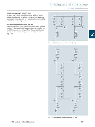
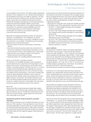
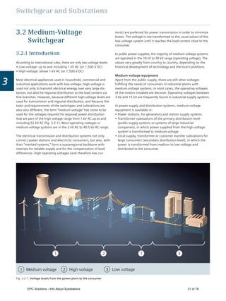
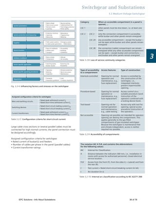
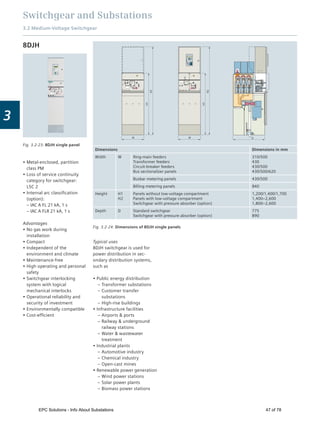
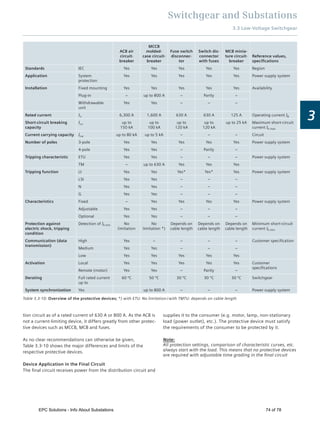
Arc resistance
Arcing faults can be caused by incorrect dimensioning and
reductions in insulation due to contamination etc., but they can
also be a result of handling errors. The effects, resulting from
high pressure and extremely high temperatures, can have fatal
consequences for the operator, the system and even the
building. SIVACON offers effidence of personal safety through
testing under arcing fault conditions with a special test in accor-
dance with IEC 61641 (DIN VDE 0660-500 Addendum 2).
Active protection measures such as the high-quality insulation
of live parts (e.g. busbars), standardized and simple operation,
prevent arcing faults and the associated personal injuries. Passive
protections increase personal and system safety many times over.
These include: hinge and locking systems with arc resistance, the
safe operation of withdrawable units or circuit breakers behind a
closed door and patented swing check valves behind venitlation
openings on the front, arcing fault barriers or arcing fault detection
system combined with the rapid disconnection of arcing faults.
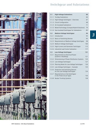
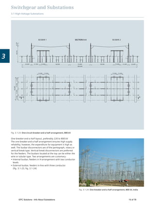
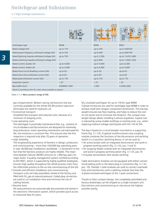
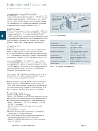
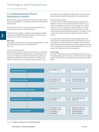
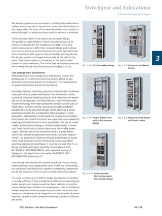
Fig. 3.3-15: The arcing fault levels describe the classiication in accrdance with the characteristics under arcing fault conditions and the
restriction of the eects of the arcing fault to the system or system section
Level 1
High level of
personal safety
without major
restriction of the
effects of arcing
within the power
distribution board.
Level 2
High level of
personal safety
with restriction of
the effects of
arcing on a single
section or double
fronted section.
Level 3
High level of
personal safety
with restriction to
main busbar
compartment in
single- or double
fronted section as
well as device or
cable connection
compartments.
Level 4
High personal
safety with
restriction of the
effects of arcing to
the site of origin.
EPC Solutions - Info About Substations 69 of 78](https://image.slidesharecdn.com/substationsinformationguide-160716135309/85/EPC-Solutions-All-About-Substation-69-320.jpg)
![Switchgear and Substations
3.3 Low-Voltage Switchgear
3
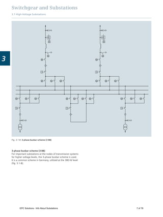
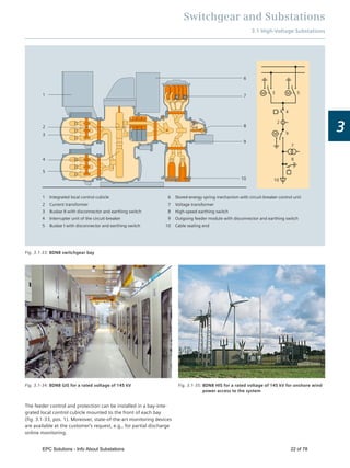
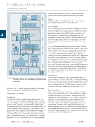
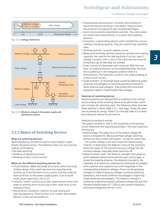
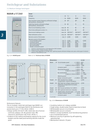
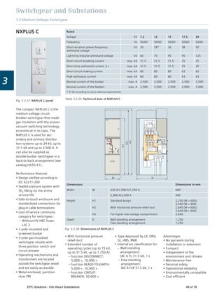
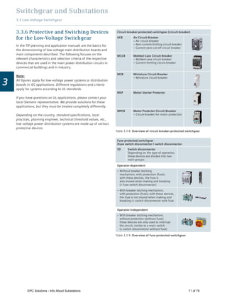
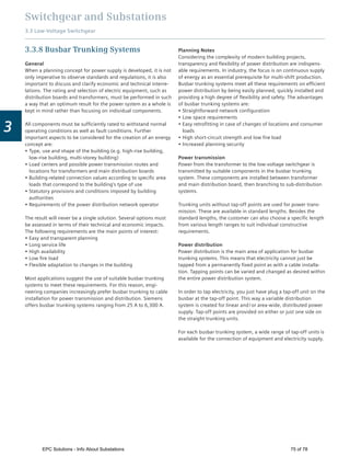
3.3.5 Low-Voltage Switchgear – Example
Table 3.3-7: Various mounting designs according to panel types
Panel type Circuit-breaker
design
Universal
mounting design
3NJ6 in-line switch-
disconnector
design
Fixed-
mounted
design
3NJ4 in-line switch-
disconnector
design
Reactive power
compensation
Mounting design
Fixed mounting
Withdrawable-unit
design
Fixed mounting
Plug-in design
Withdrawable-unit
design
Plug-in design
Fixed-mounted
design with
front covers
Fixed mounting Fixed mounting
Function Incoming feeder
Outgoing feeder
Coupling
Cable feeders
Motor feeders
Cable feeders Cable feeders Cable feeders
Central
compensation of
the reactive power
Current In
Up to 6,300 A
Up to 630 A /
Up to 250 kW
Up to 630 A Up to 630 A Up to 630 A Up to 600 kvar
Connection Front and rear
side
Front and rear side Front side Front side Front side Front side
Panel width [mm] 400 / 600 / 800 /
1,000 / 1,400
600 / 1,000 / 1,200 1,000 / 1,200 1,000 / 1,200 600 / 800 800
Internal compart-
mentalization
1, 2b, 3a, 4b 4a, 3b, 4b 1, 3b, 4b
1, 2b, 3b, 4a,
4b
1, 2b 1, 2b
Busbars Rear / top Rear / top Rear / top Rear / top Rear Rear / top / without
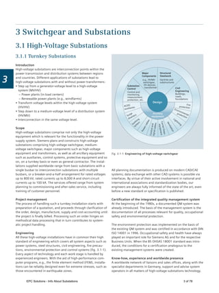
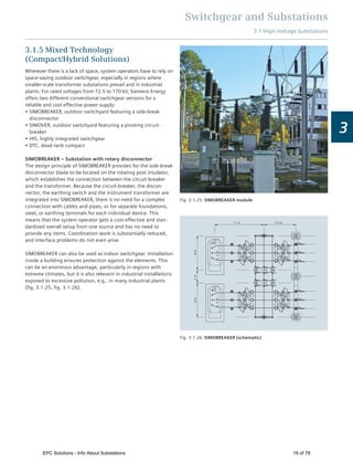
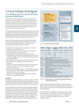
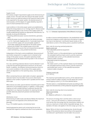
Fig. 3.3-16: SIVACON S8, busbar position at rear 2,200 × 4,800 × 600 (H × W × D in mm)
Free space in the
fastening plane for
cable and busbar
penetration
D
Panel width
Panel depth
Boring 4 x Ø 14,8 mm
Threaded hole M12
Depth 800, 1000, 1200
(depth 800 only for
main busbar at top)
Installation front
Installation front
Circuit-
breaker
design
Universal
mounting
design
Plug-in 3NJ6 in-line
switch-disconnector
design
Fixed 3NJ4 in-line
switch-discon-
nector design
Reactive power
compensation
Fixed-mounting
with front cover
Boring 4 x Ø 14,8 mm
Threaded hole M12
W
Depth 500, 600, 800
(depth 800 only for
main busbar at rear)
W–150
W–100
W–150
W–100
D
D–50
D–50
D–350
D
W W
B
A
B
A
C B
A
D B
A
E B
A
F B
A
G B
A
H B
A
J B
A
K B
A
L B
A
M B
A
N B
A
P B
A
Q B
A
R B
A
S B
A
T B
A
U B
A
V
0
200
400
600
0
200
400
600
800
1000
1200
1400
1600
1800
2000
2200
4800
75
50
25
300
50
300
75
50
25
300
50
400 1000 1000 1000 600 800
EPC Solutions - Info About Substations 70 of 78](https://image.slidesharecdn.com/substationsinformationguide-160716135309/85/EPC-Solutions-All-About-Substation-70-320.jpg)
![Switchgear and Substations
3.3 Low-Voltage Switchgear
3
Table 3.3-11: Cable / busbar comparison
Characteristic Cable Busbar
Planning, calculation High determination and calculation expense, the
consumer locations must be fixed
Flexible consumer locations, only the total load is
required for the planning
Expansions, changes High expense, interruptions to operation, calculation,
risk of damage to the insulation
Low expense as the tap-off units are hot pluggable
Space requirements More space required because of bending radiuses and
the spacing required between parallel cables
Compact directional changes and fittings
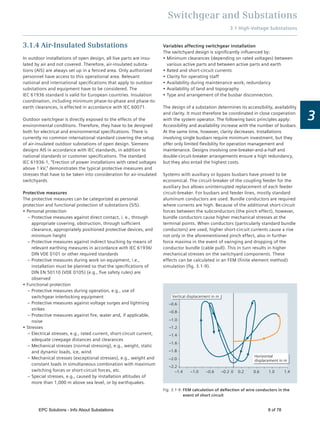
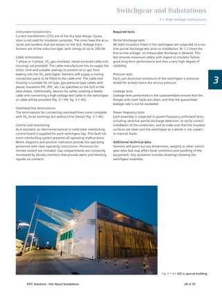
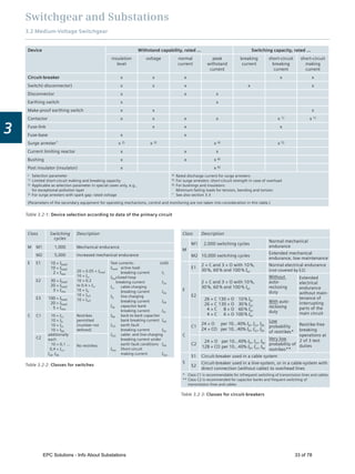
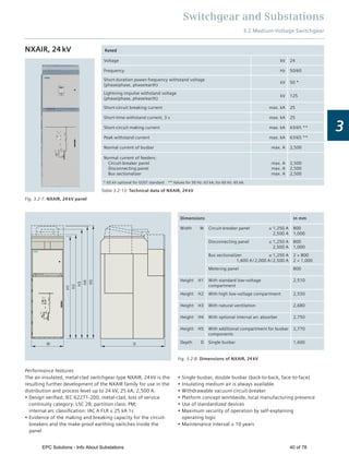
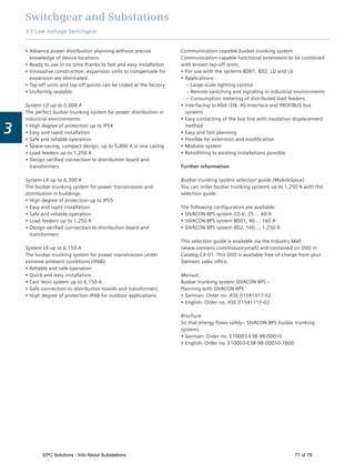
Temperature responses
and derating
Limits depend on the laying method and cable
accumulation. The derating factor must be
determined / calculated
Design verified switchgear assembly, limits from
catalog
Free from halogen PVC cables are not free from halogen; halogen-free
cable is very expensive
Principally free from halogen
Fire load Fire load with PVC cable is up to 10 times greater, with
PE cable up to 30 times greater than with busbars
Very low, see catalog
Design verified switchgear assembly The operational safety depends on the version Tested system, non-interchangeable assembly
Benefits
System CD-K up to 40 A
The versatile busbar trunking system for area-wide power
distribution to lighting systems:
Versatile thanks to high degree of protection IP55
Lower planning costs through simple configuration
Quick-release plug-in connection for fast assembly
Variable changes of direction
Optimum utilization of the busbar line through tap-off points
fitted to both sides
Uniform current loading of the conductors through splitting of
the tap-off plugs among the individual phases
Tap-off plugs allow fast and flexible load relocation
Transmission of the KNX, DALI protocol for intelligent lighting
control directly via the busbar
System BD01 up to 160 A
The busbar trunking system for power distribution in trade and
commerce:
High degree of protection up to IP55
Flexible power supply
Easy and fast planning
Time-saving installation
Reliable mechanical and electrical cables and connections
High stability, low weight
Small number of basic modules
Modular system reduces stock-keeping
Variable changes of direction
Multi-purpose tap-off units
Forced opening and closing of the tap-off point
System BD2 up to 1,250 A
The busbar trunking system for power distribution in the
aggressive industrial environment:
High degree of protection up to IP55
Easy and fast planning
Time-saving and economic installation
Safe and reliable operation
Flexible, modular system providing simple solutions for every
application
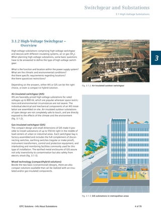
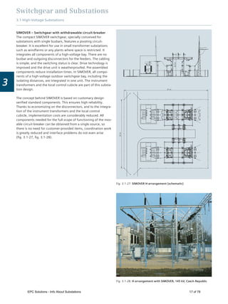
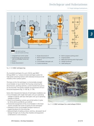
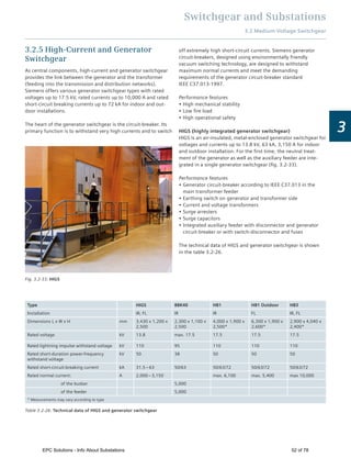
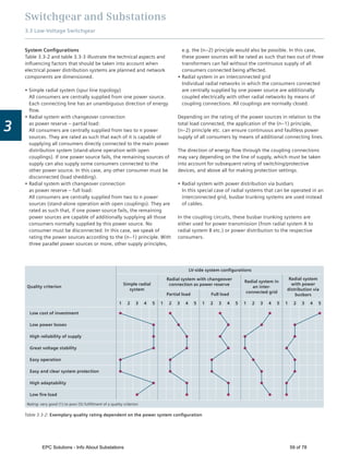
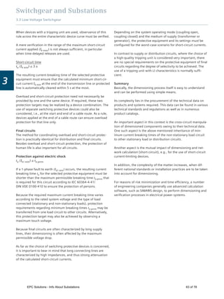
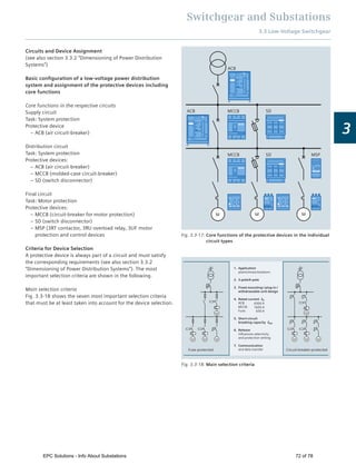
Fig. 3.3-19: Comparison of temperature response and derating
120
80
60
40
10 20 30 40 50 60 65554535252515
I =100
I[%]
140
e
e
Ambient temperature [°C]
Busbar
Cable
Fig. 3.3-20: Comparison of fire load at a rated current of 2,000 A
kWh/m
10
20
30
50
40
60
70
0
Depending on
type 10 to 30
times higher
(For example
System LDC)
7 × 3 × 185/95
9 × 3 × 120/70
PE/EPR
(halogen-free)
7 × 3 × 185/95
9 × 3 × 120/70
2–4 × PVC
EPC Solutions - Info About Substations 76 of 78](https://image.slidesharecdn.com/substationsinformationguide-160716135309/85/EPC-Solutions-All-About-Substation-76-320.jpg)


The document provides comprehensive information on high-voltage substations and switchgear, detailing their types, components, and circuit configurations. It emphasizes the significance of substations in power transmission and distribution, outlining the engineering and planning aspects that ensure reliability and safety. Key design considerations include the use of air-insulated and gas-insulated switchgear, alongside modern engineering technologies to optimize performance under various environmental conditions.


![EPC Solutions LLP- Presentation [ENERGY MANAGEMENT]](https://cdn.slidesharecdn.com/ss_thumbnails/epcsolutionsllpemin-151021083716-lva1-app6892-thumbnail.jpg?width=640&height=640&fit=bounds)


![EPC Solutions LLP- Presentation [IT Domain]](https://cdn.slidesharecdn.com/ss_thumbnails/epcsolutionllpit-151021083527-lva1-app6892-thumbnail.jpg?width=640&height=640&fit=bounds)


