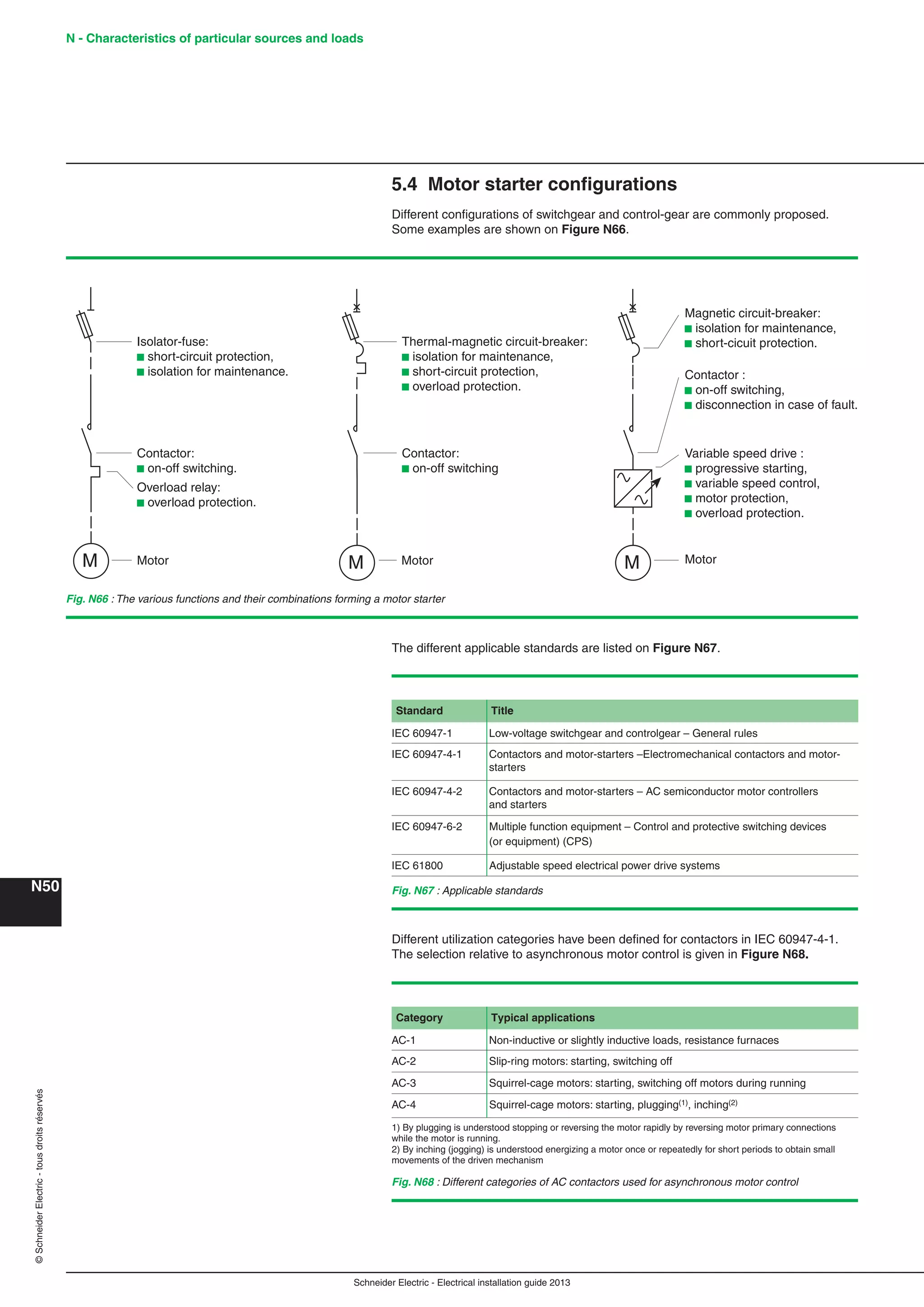
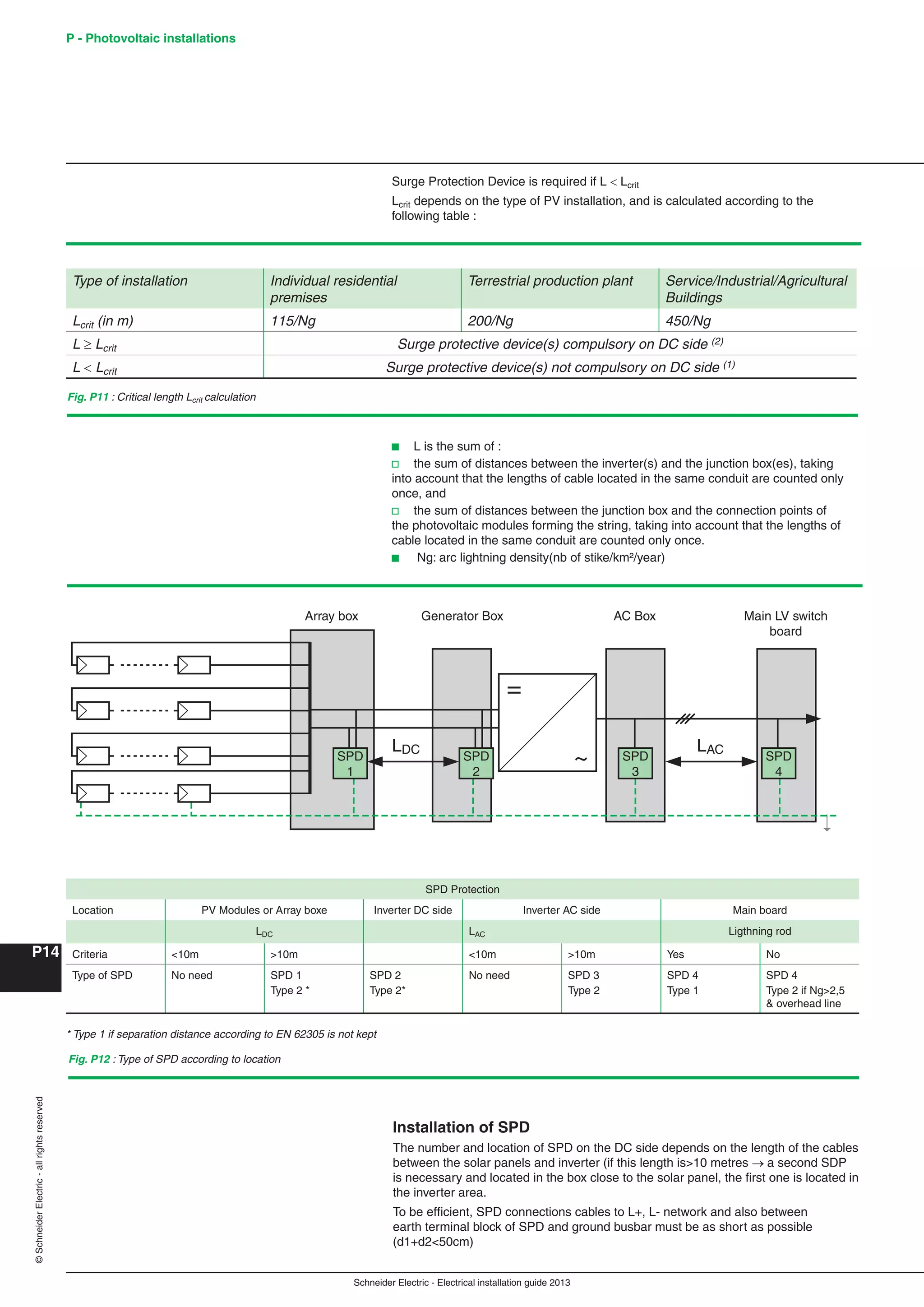
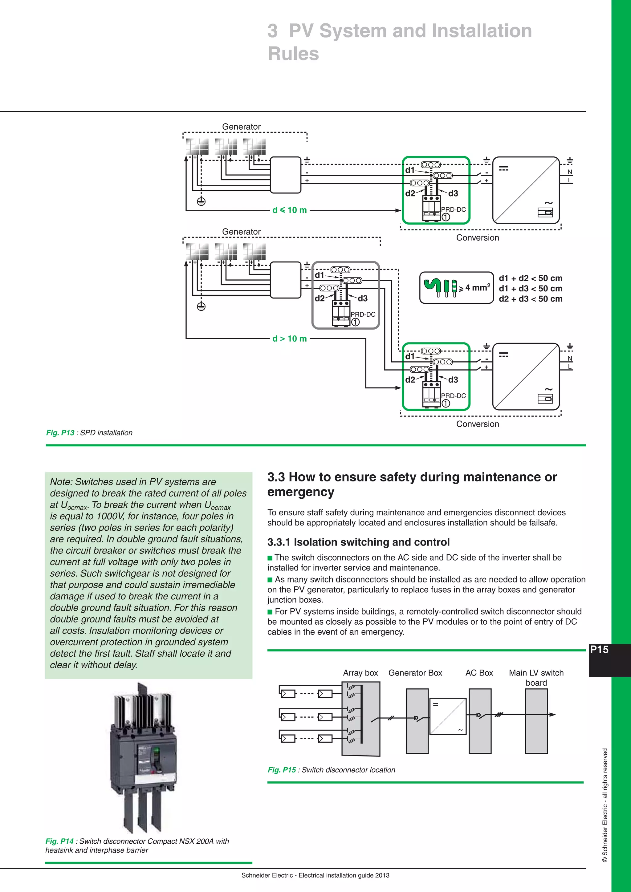
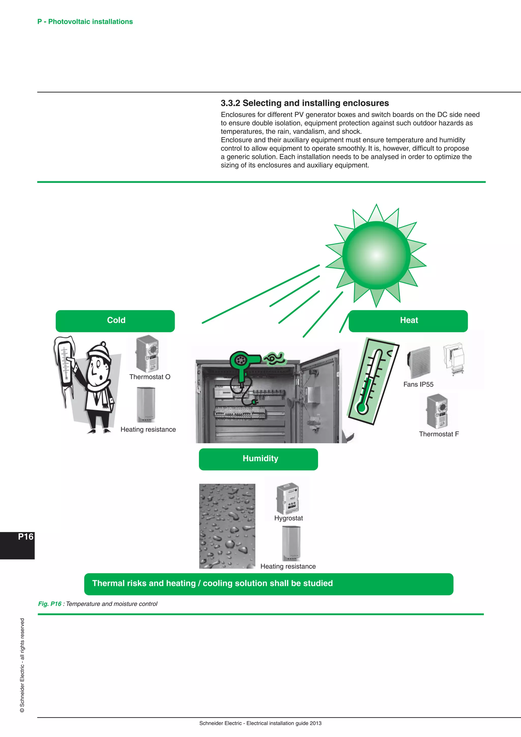
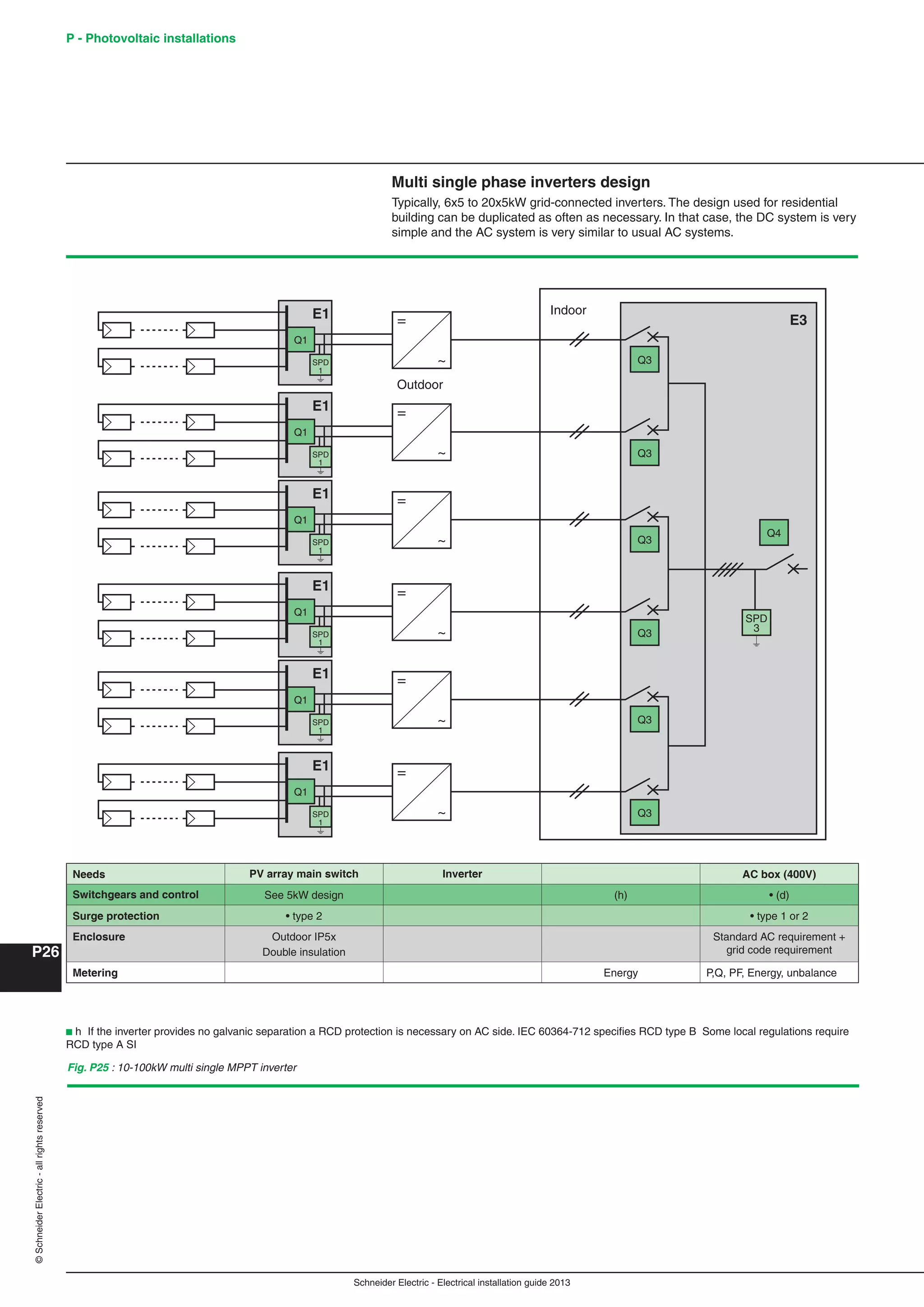
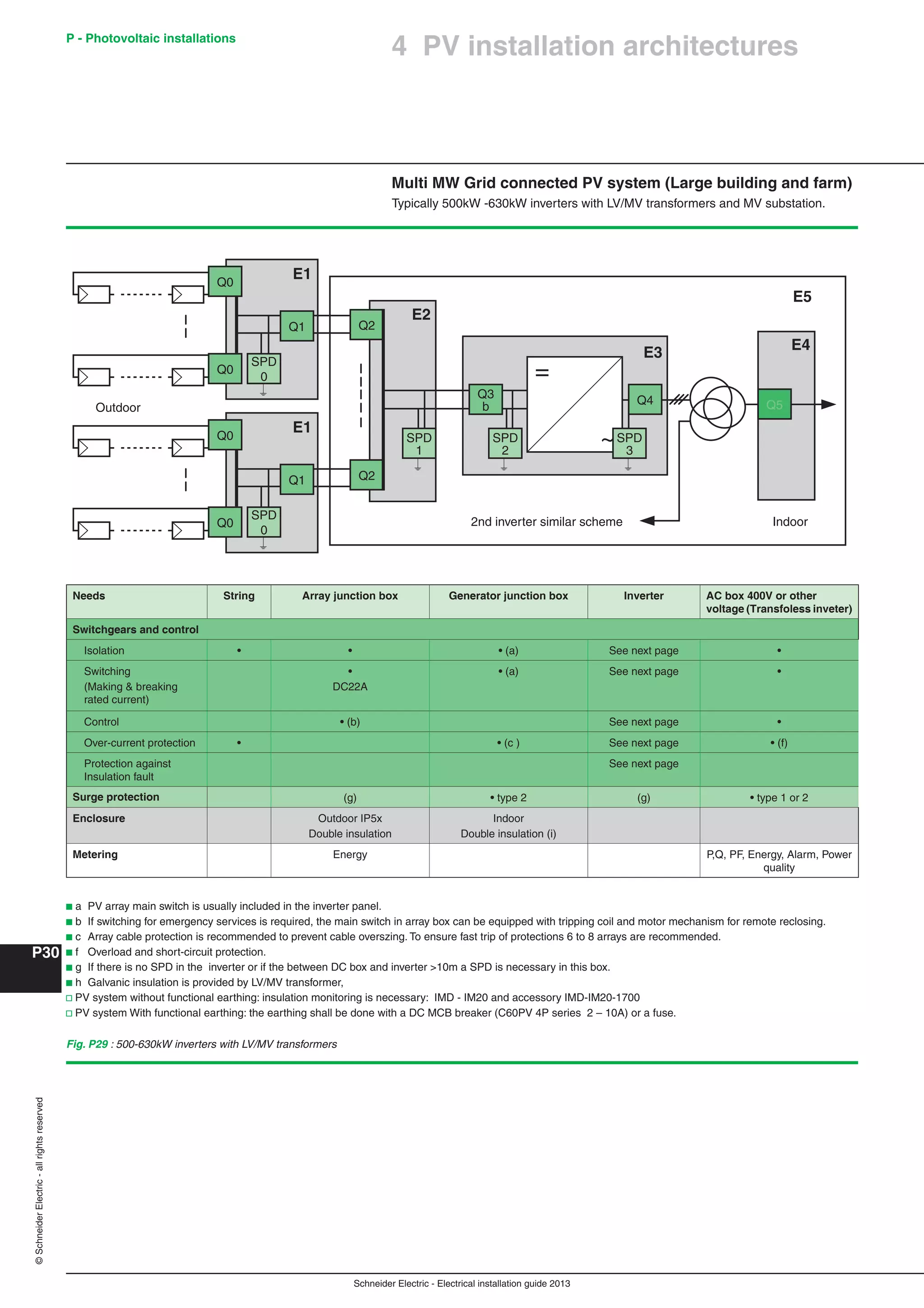
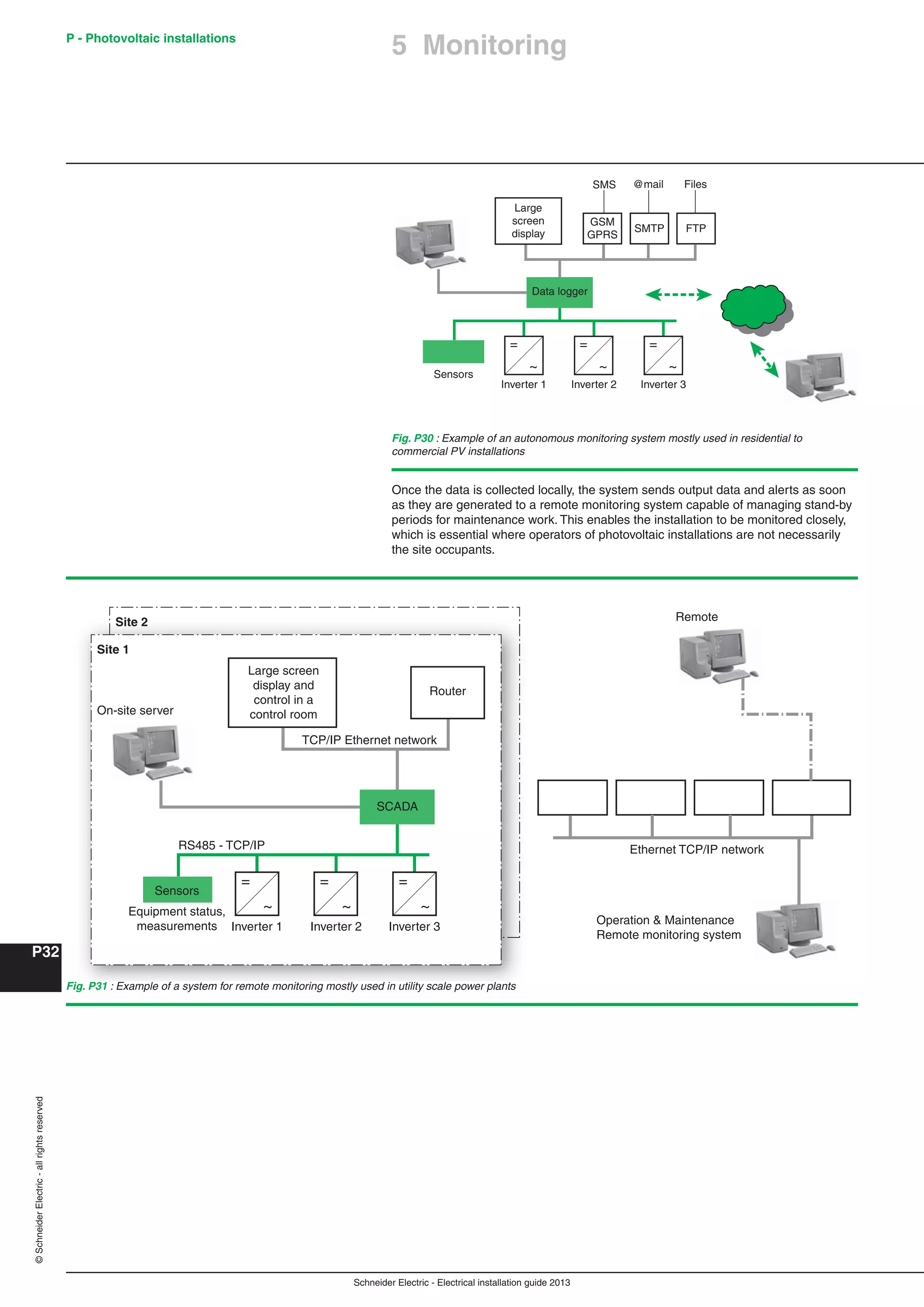
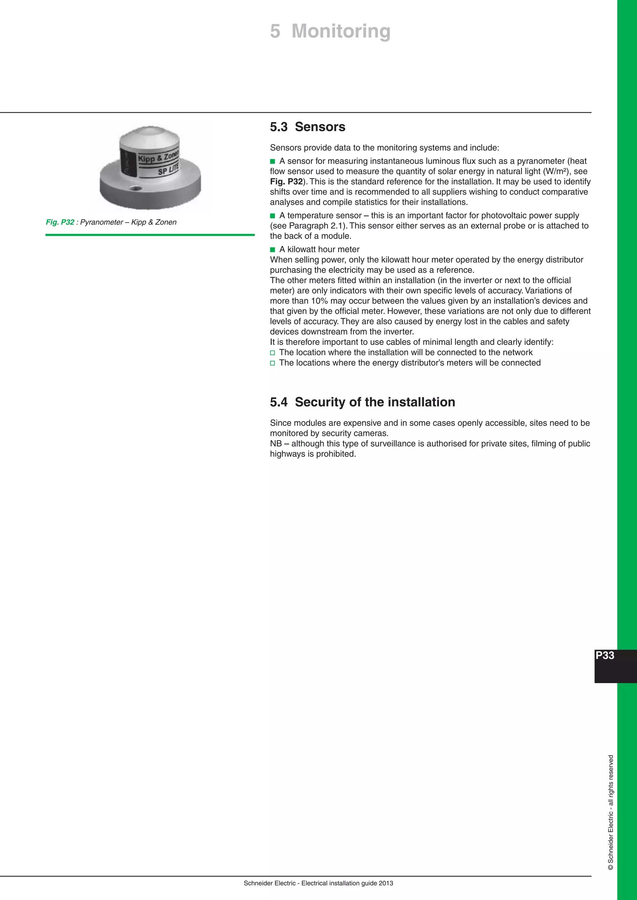
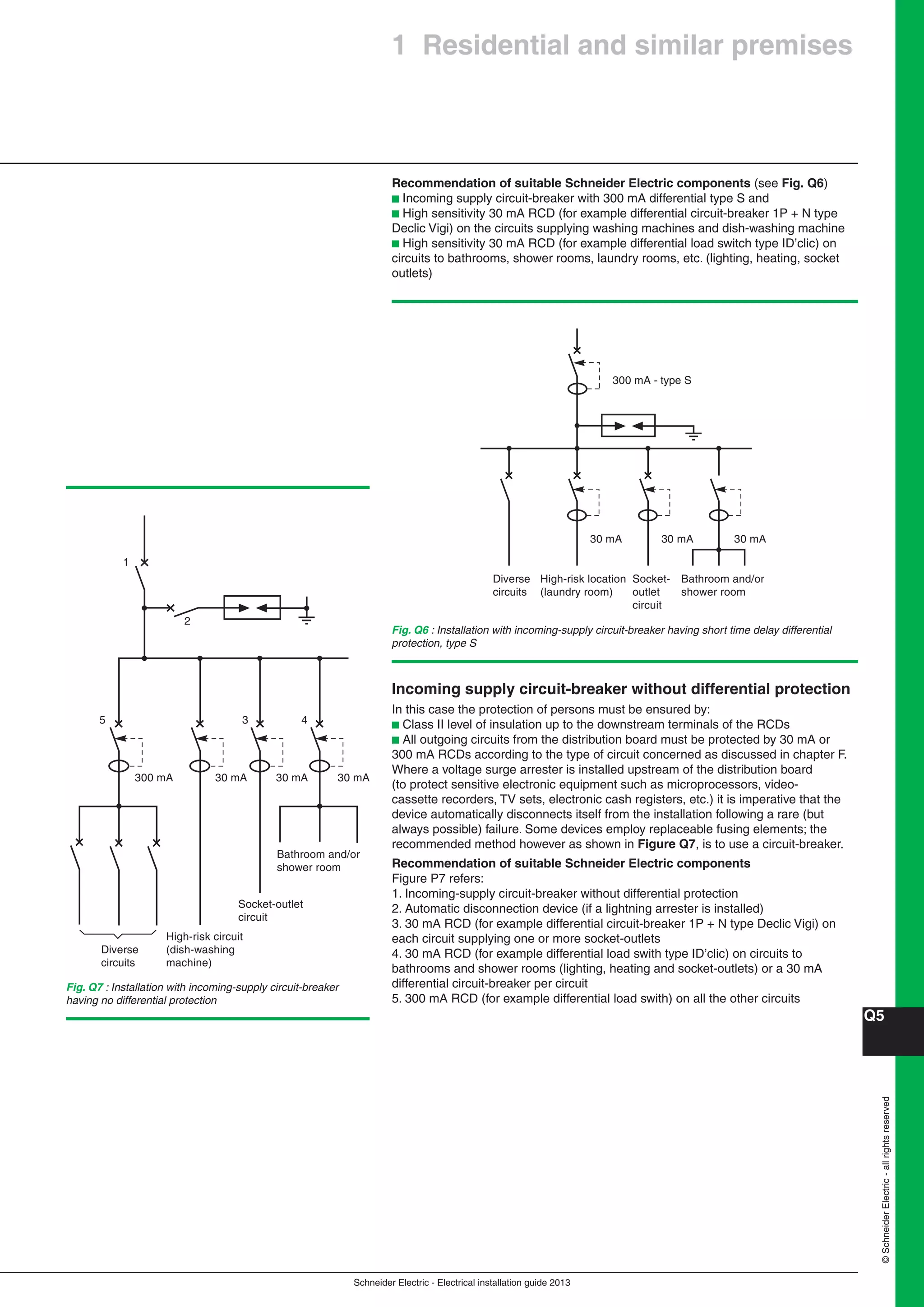
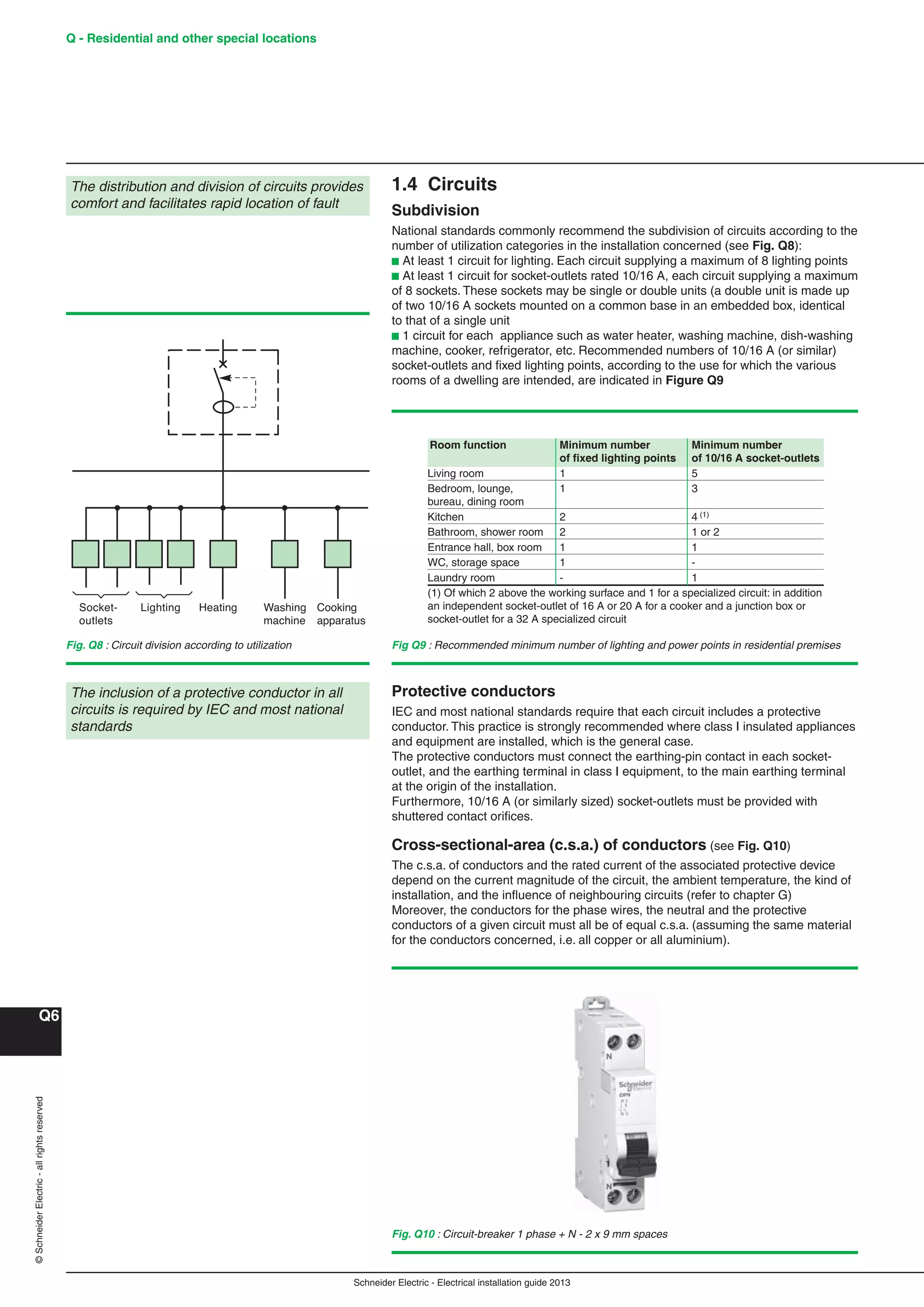
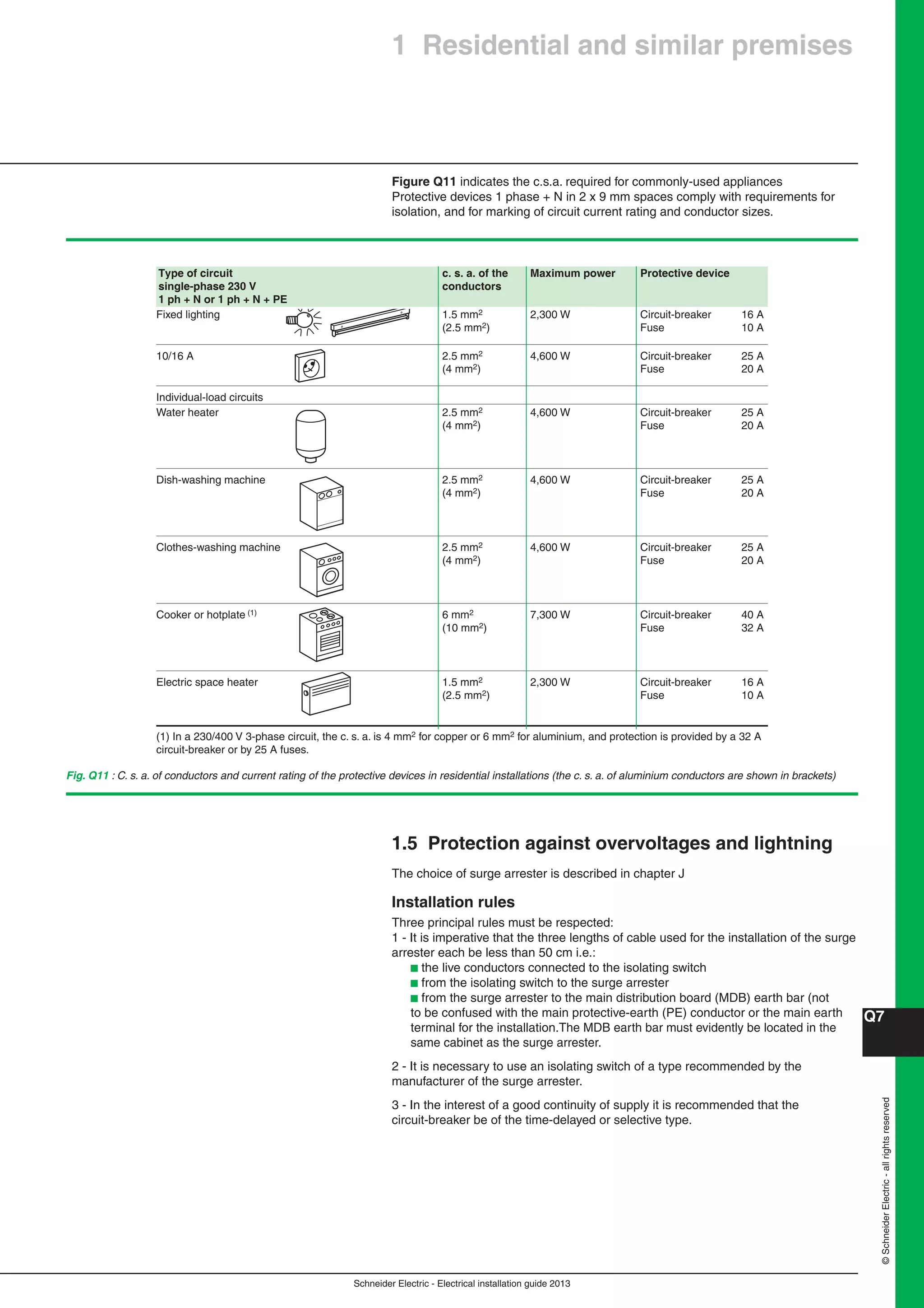
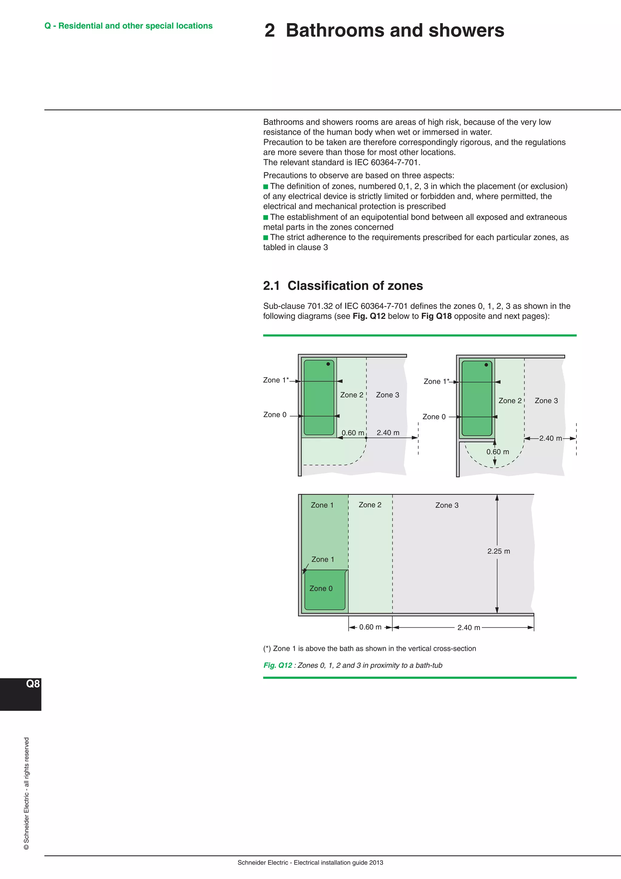
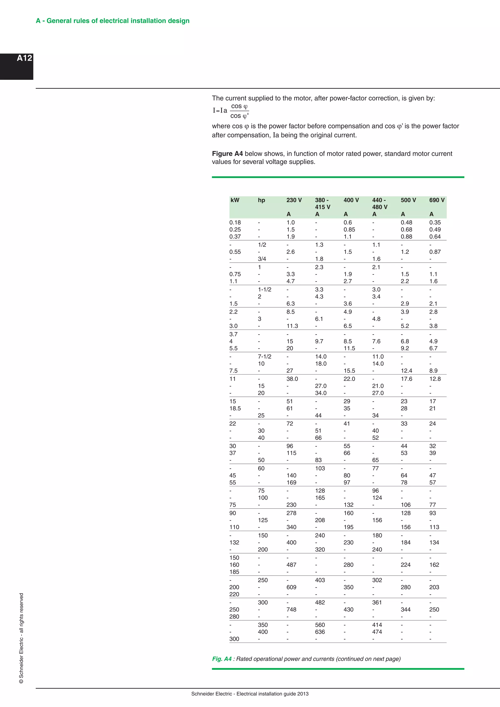
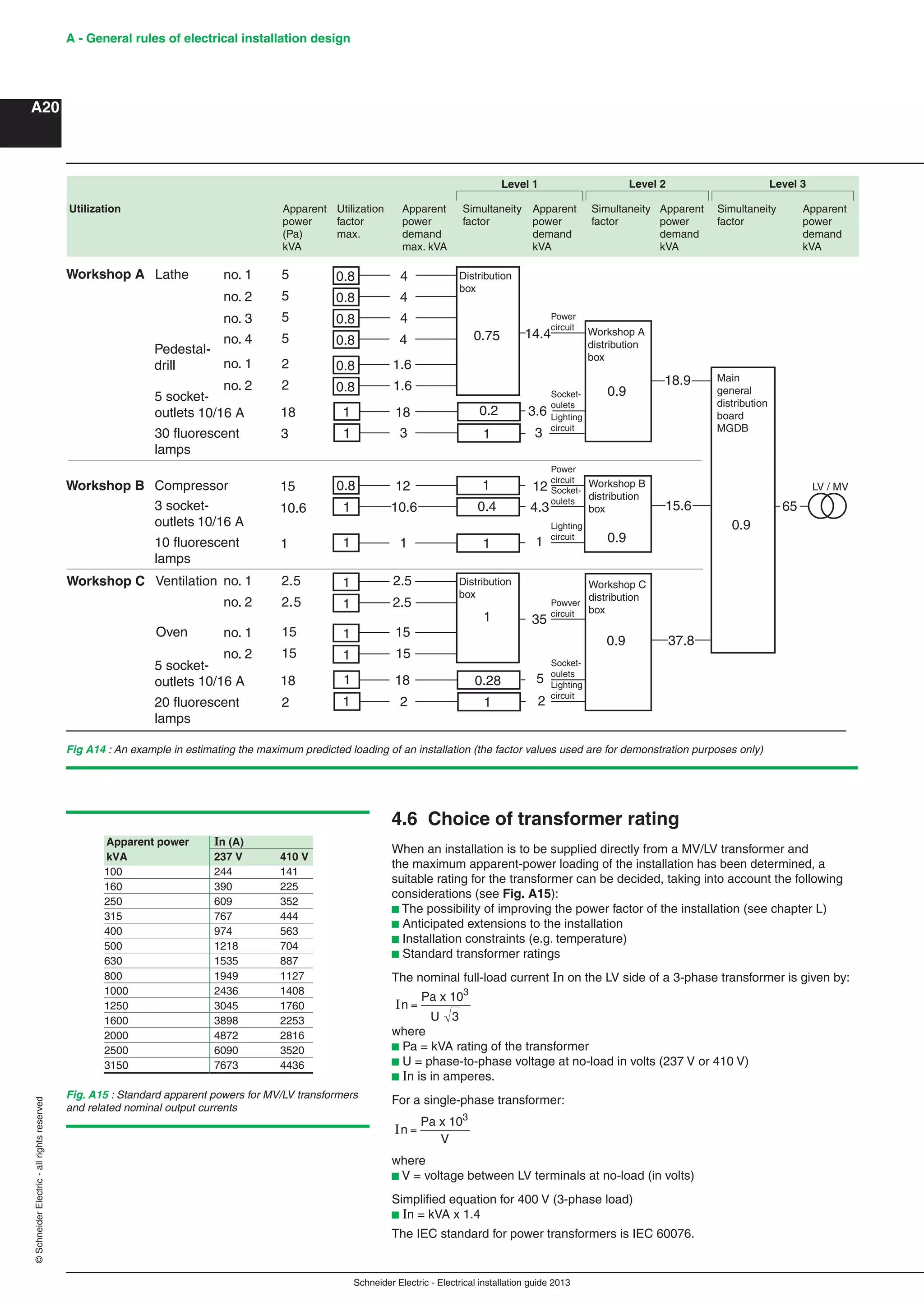
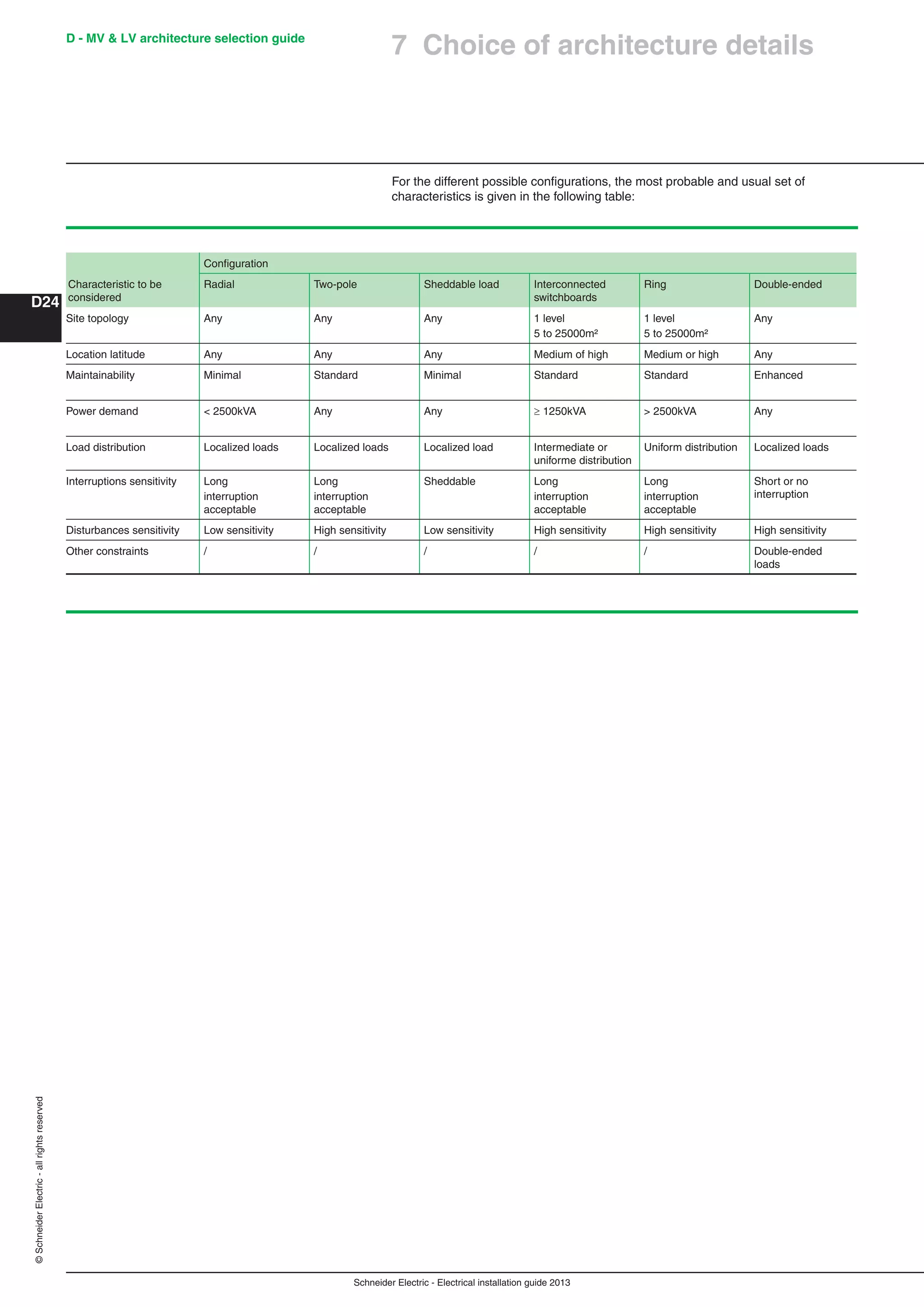
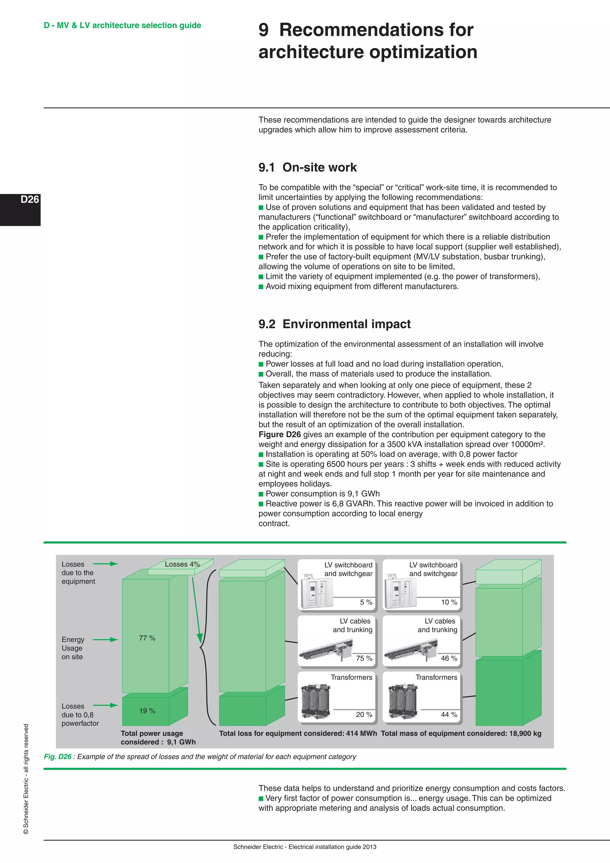
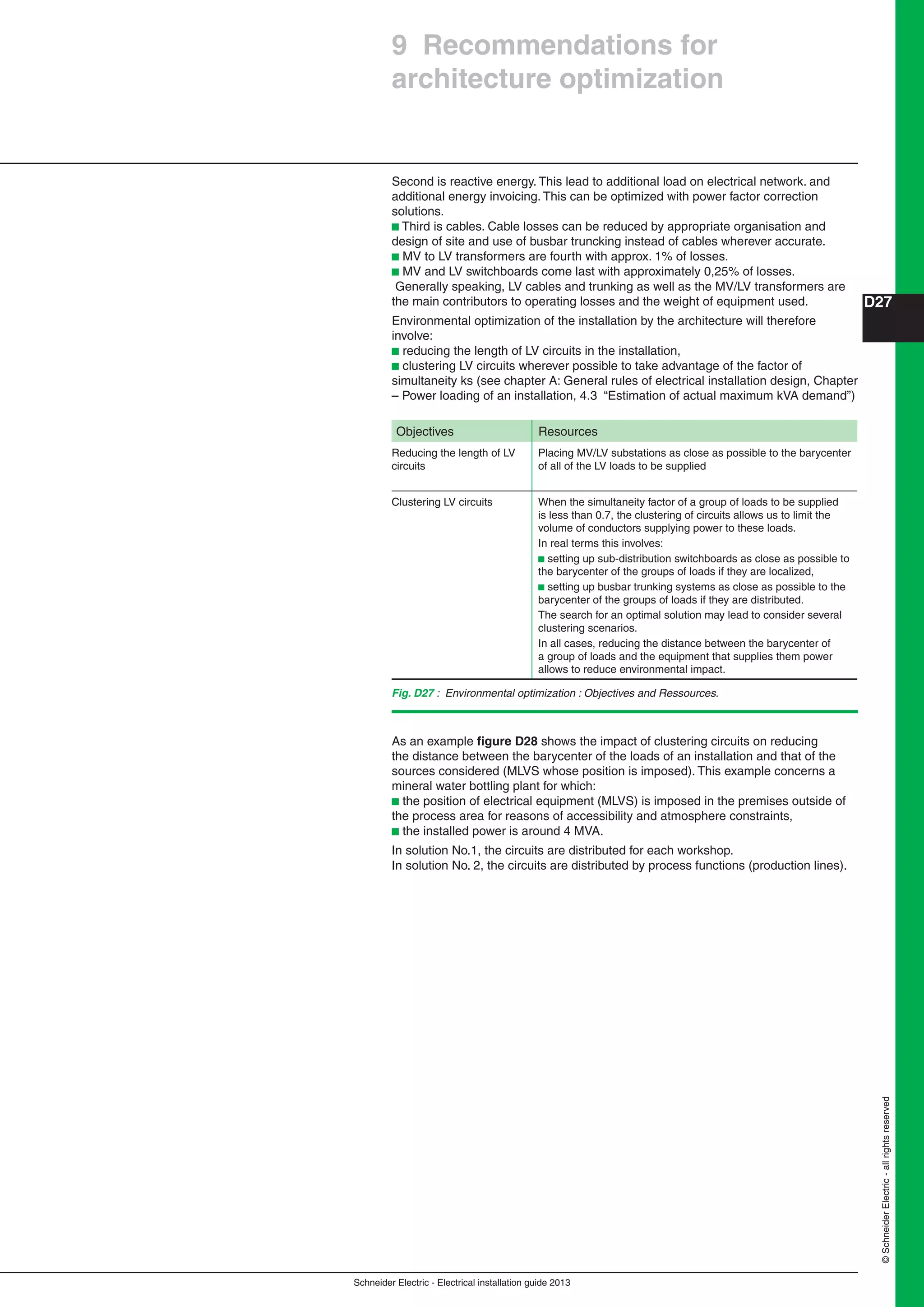
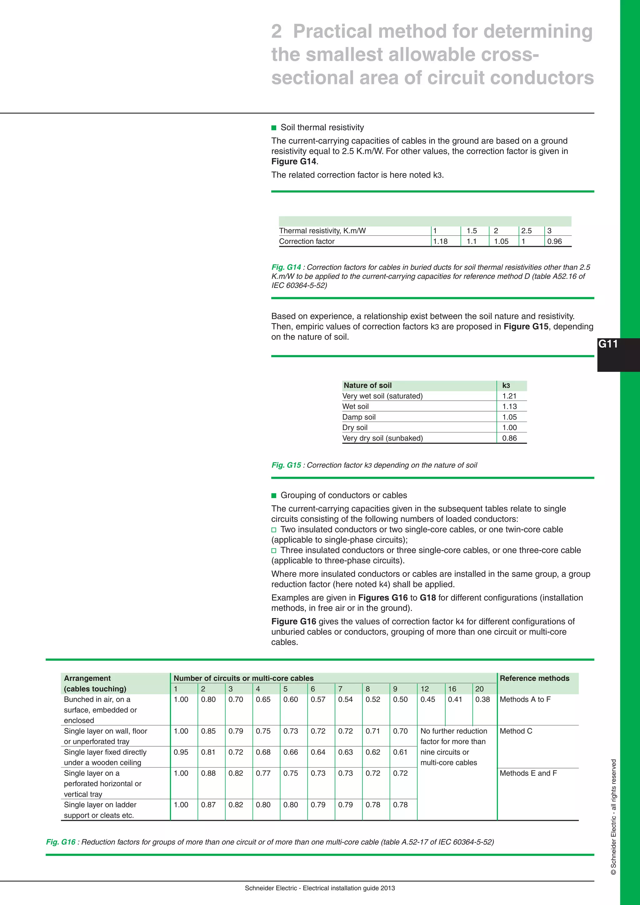
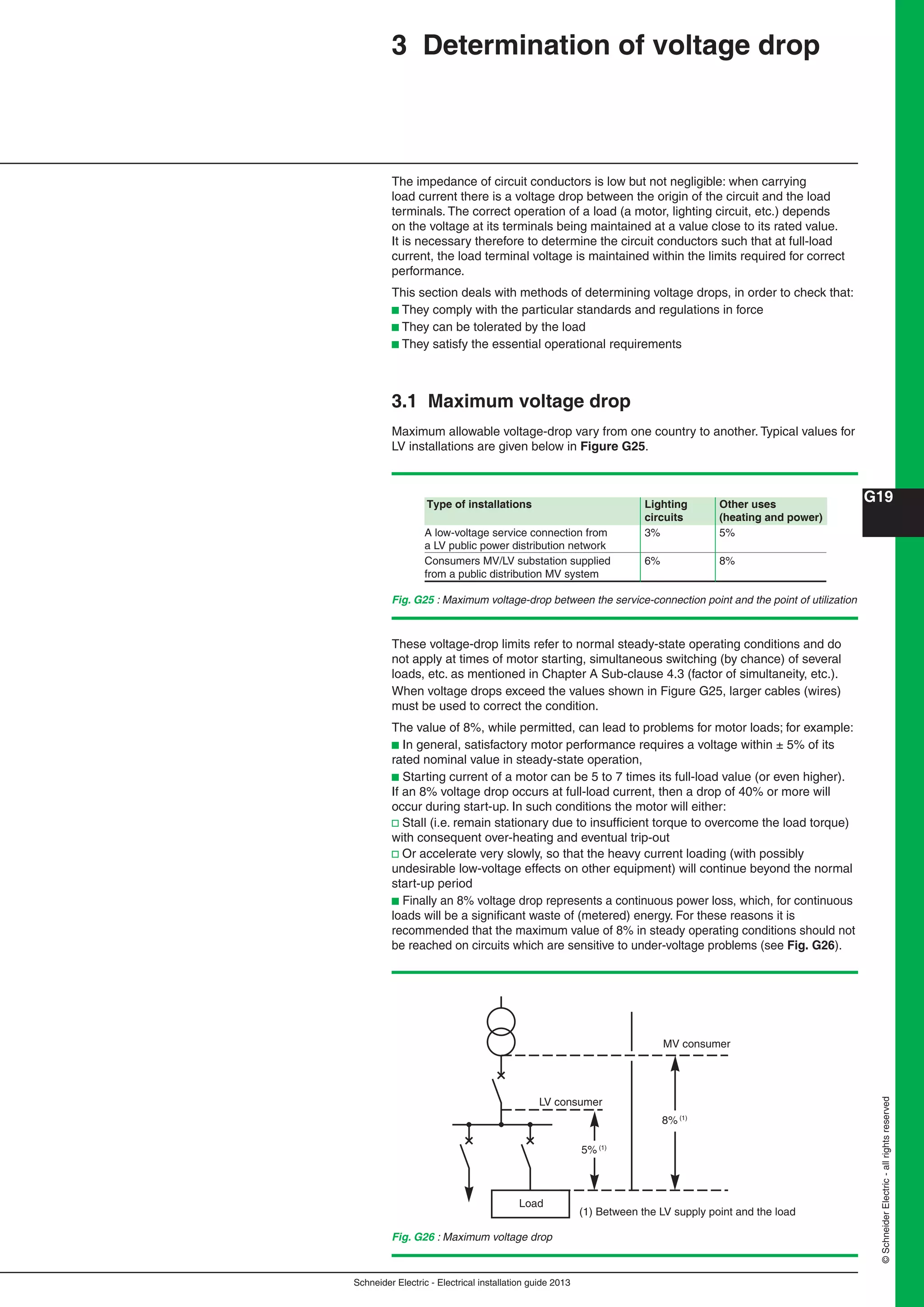
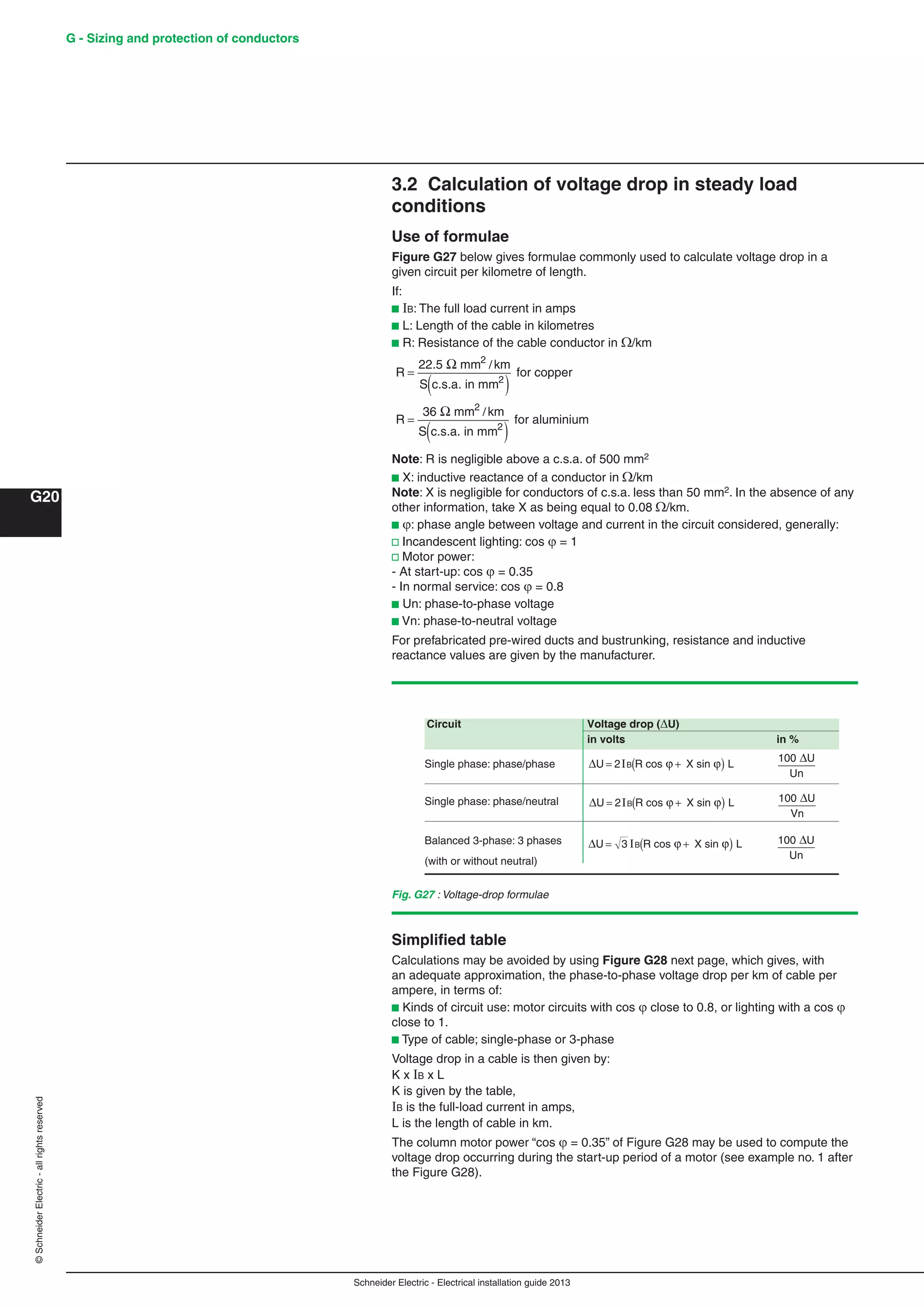
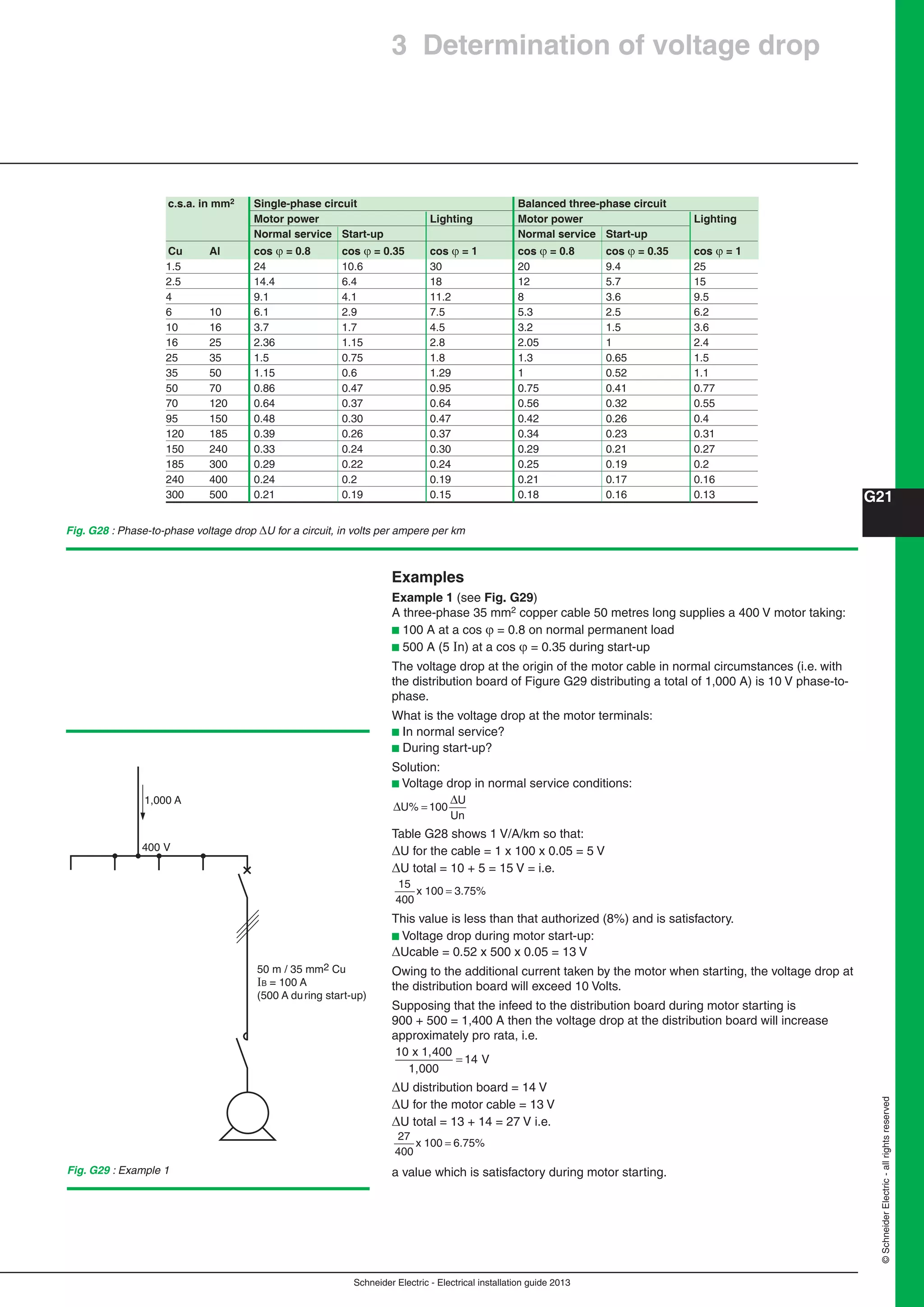
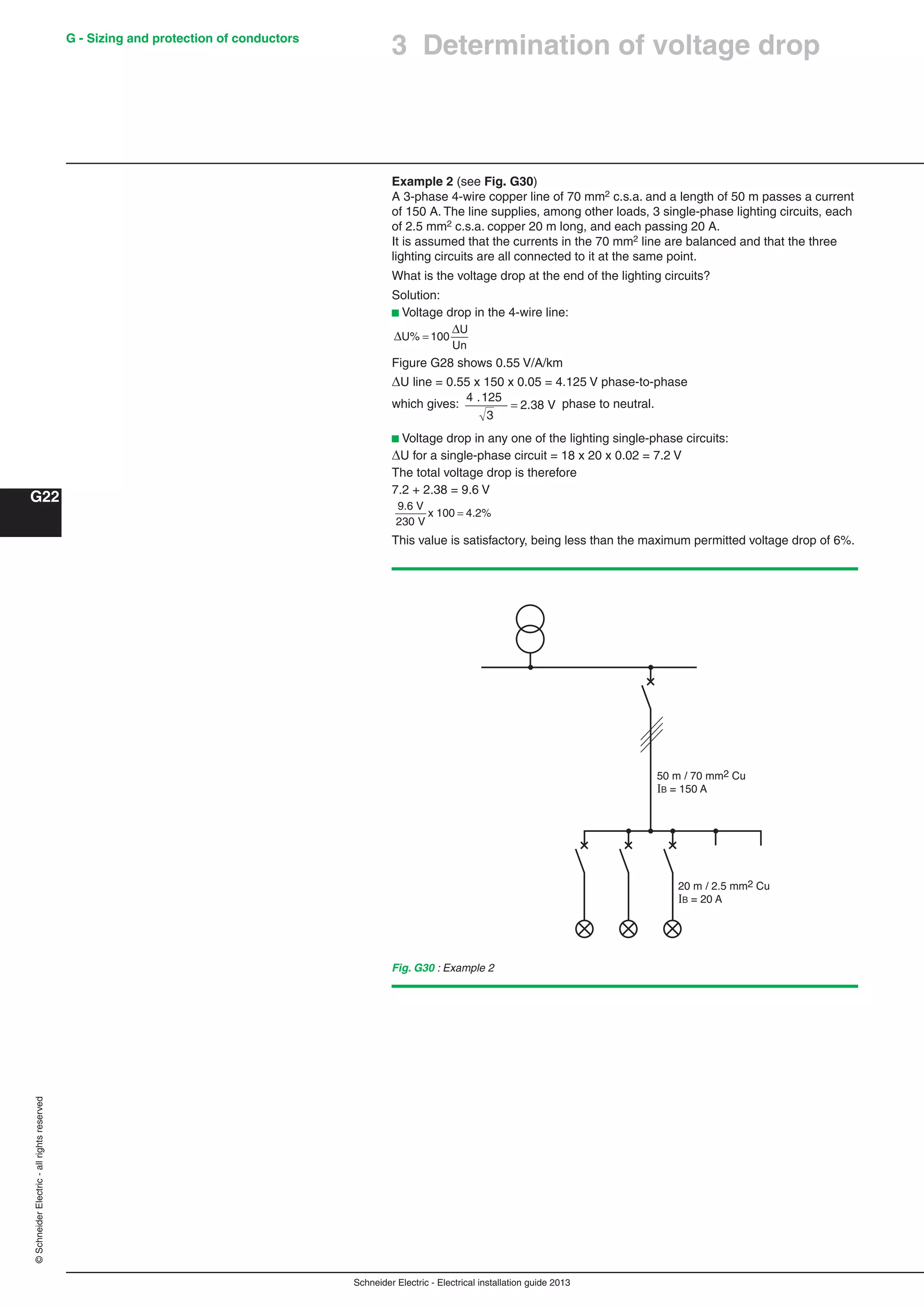
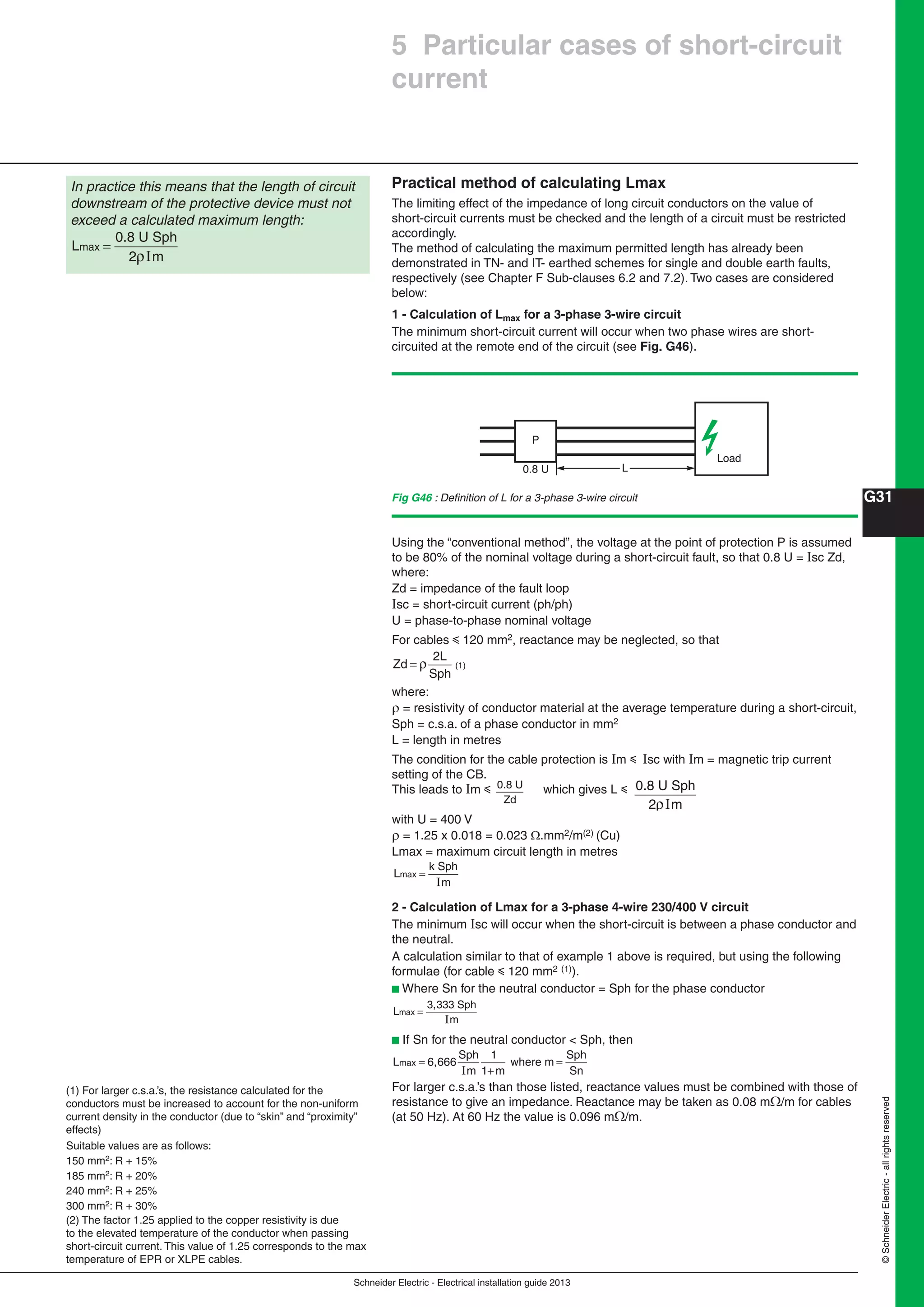
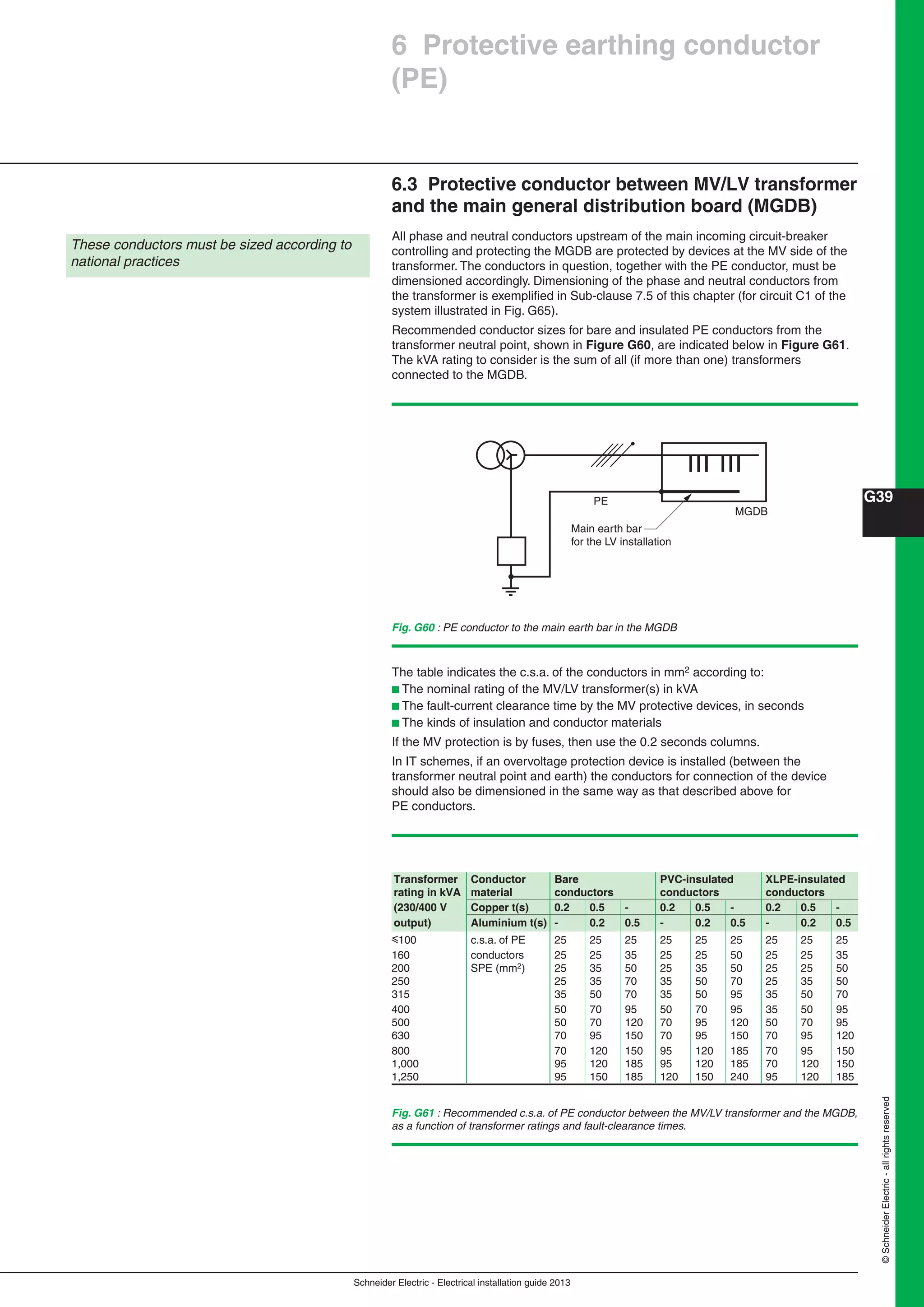
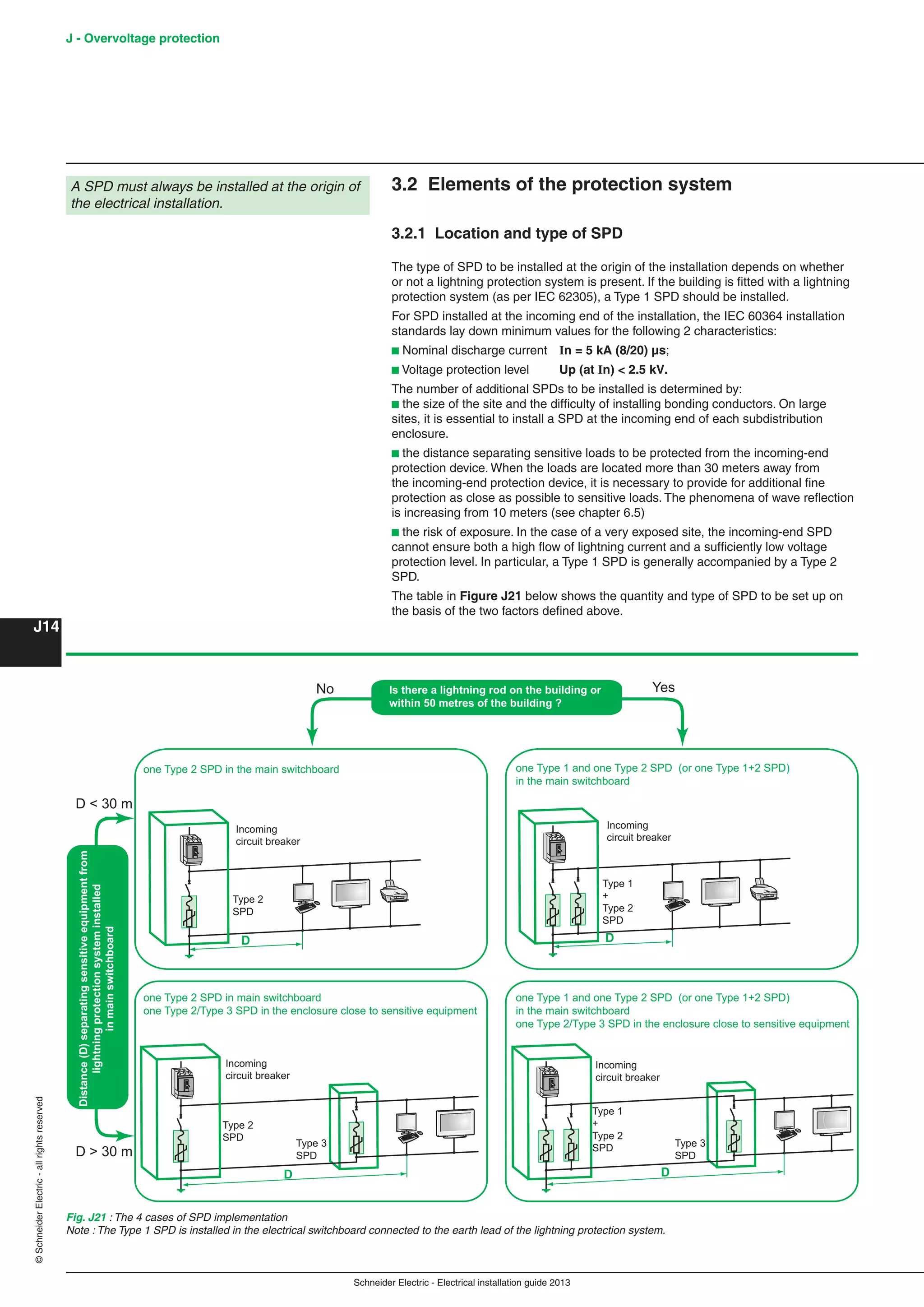
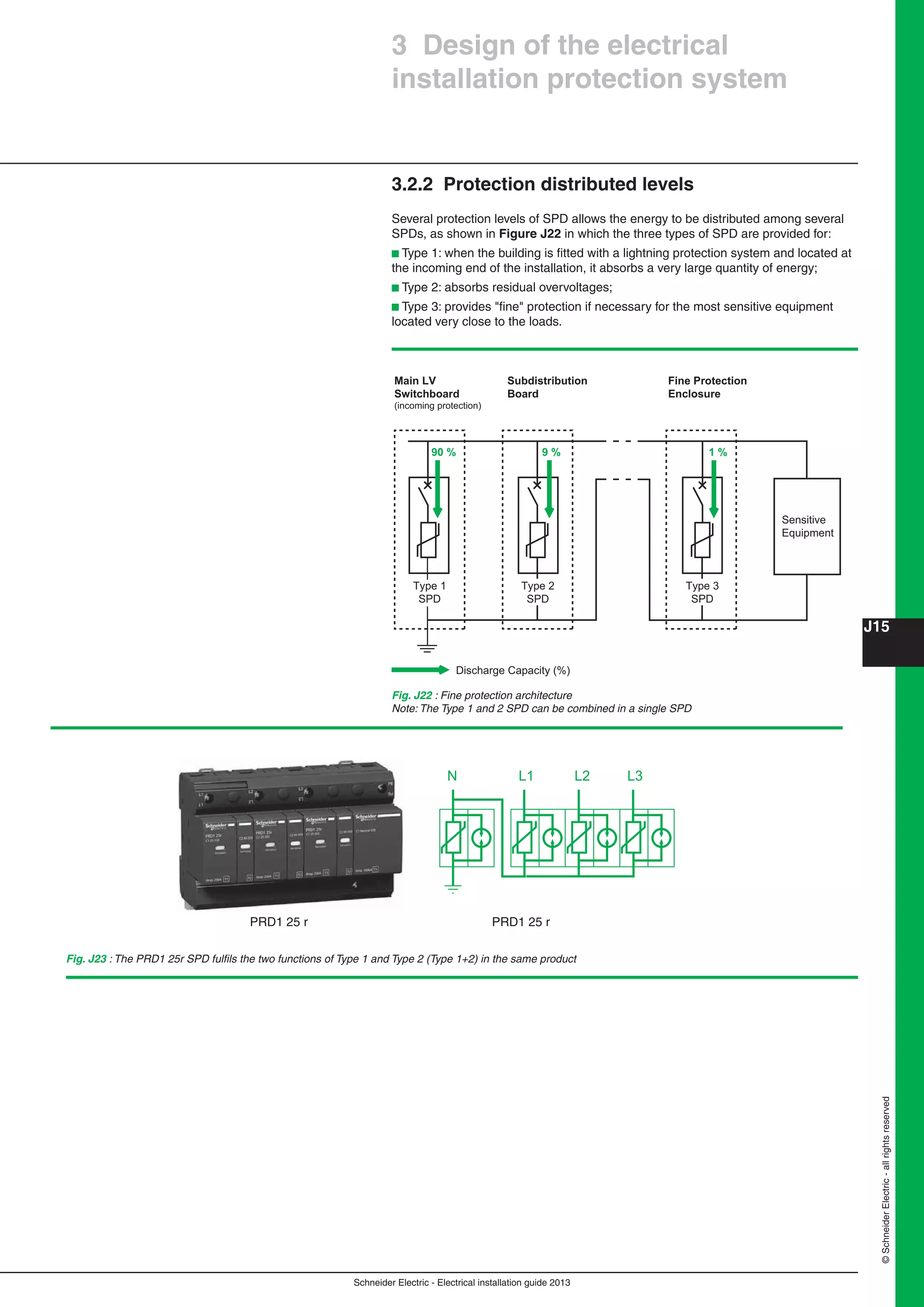
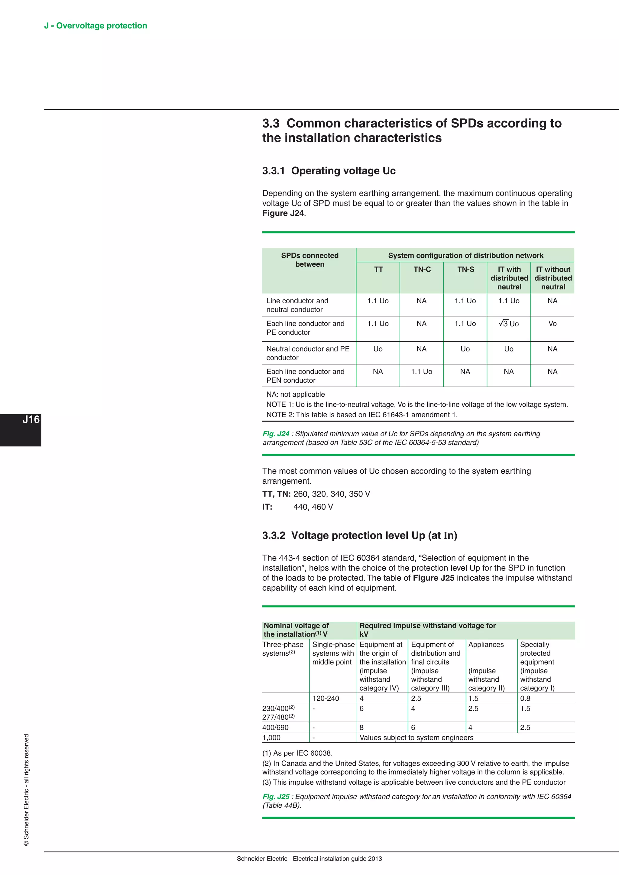
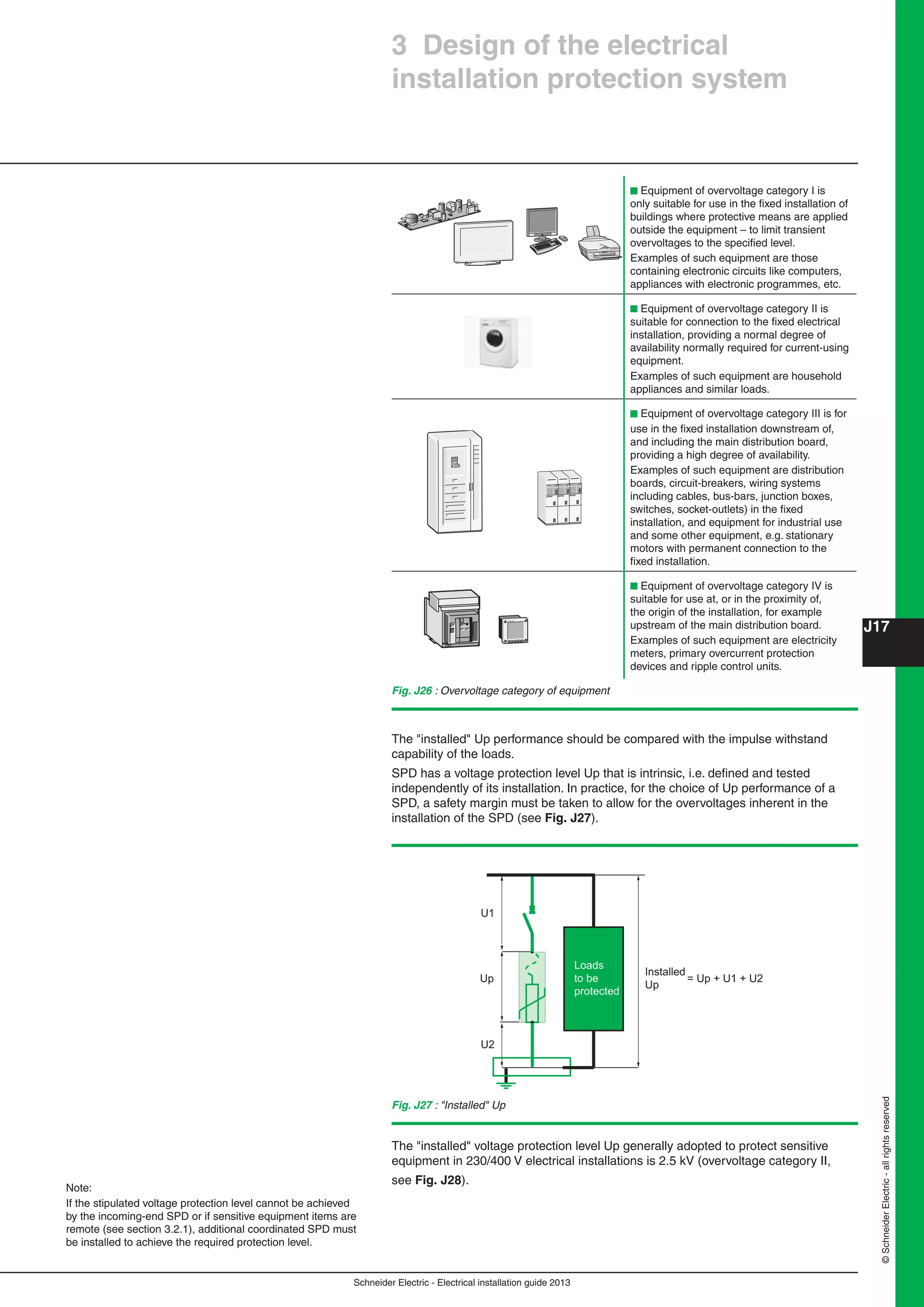
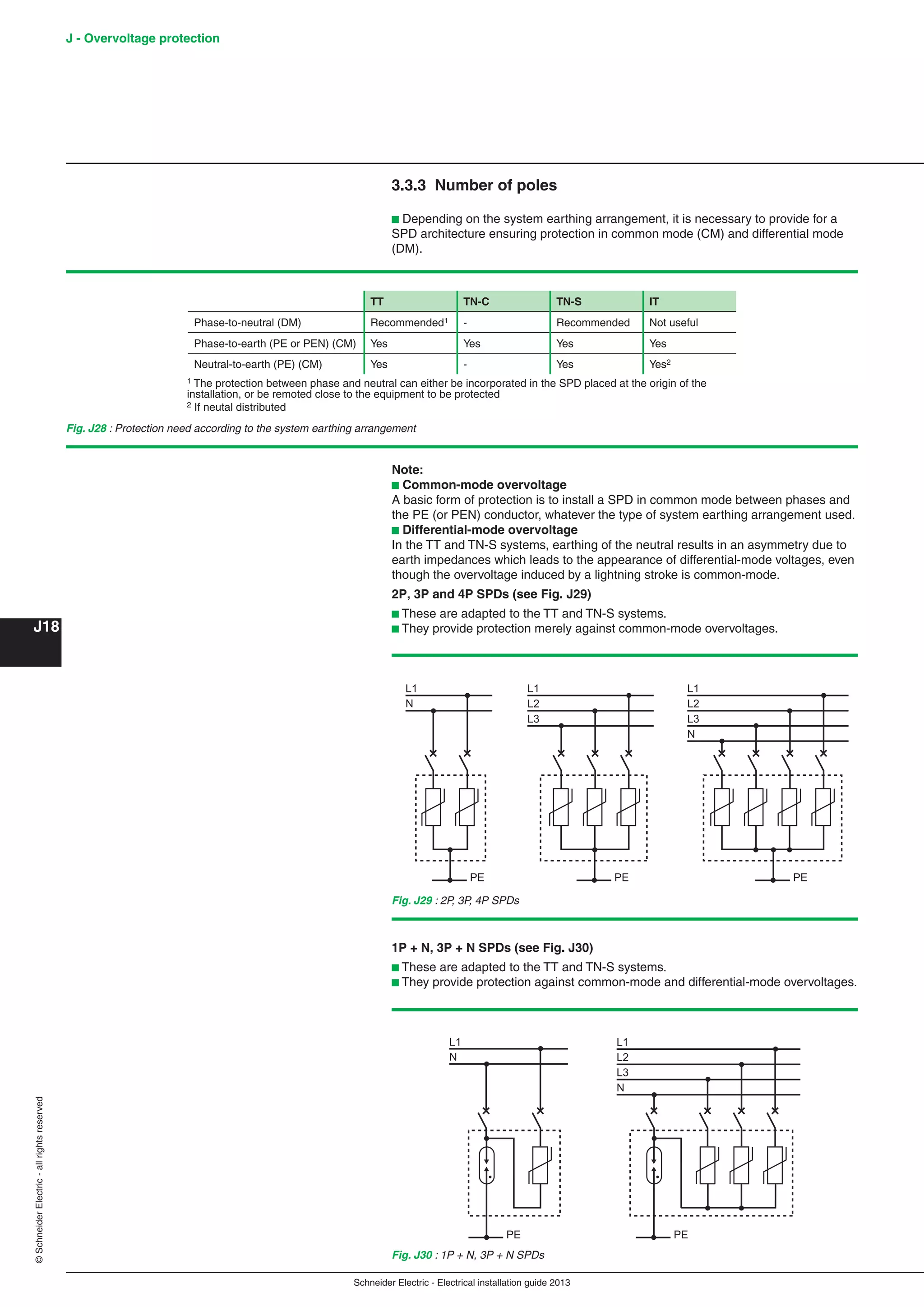
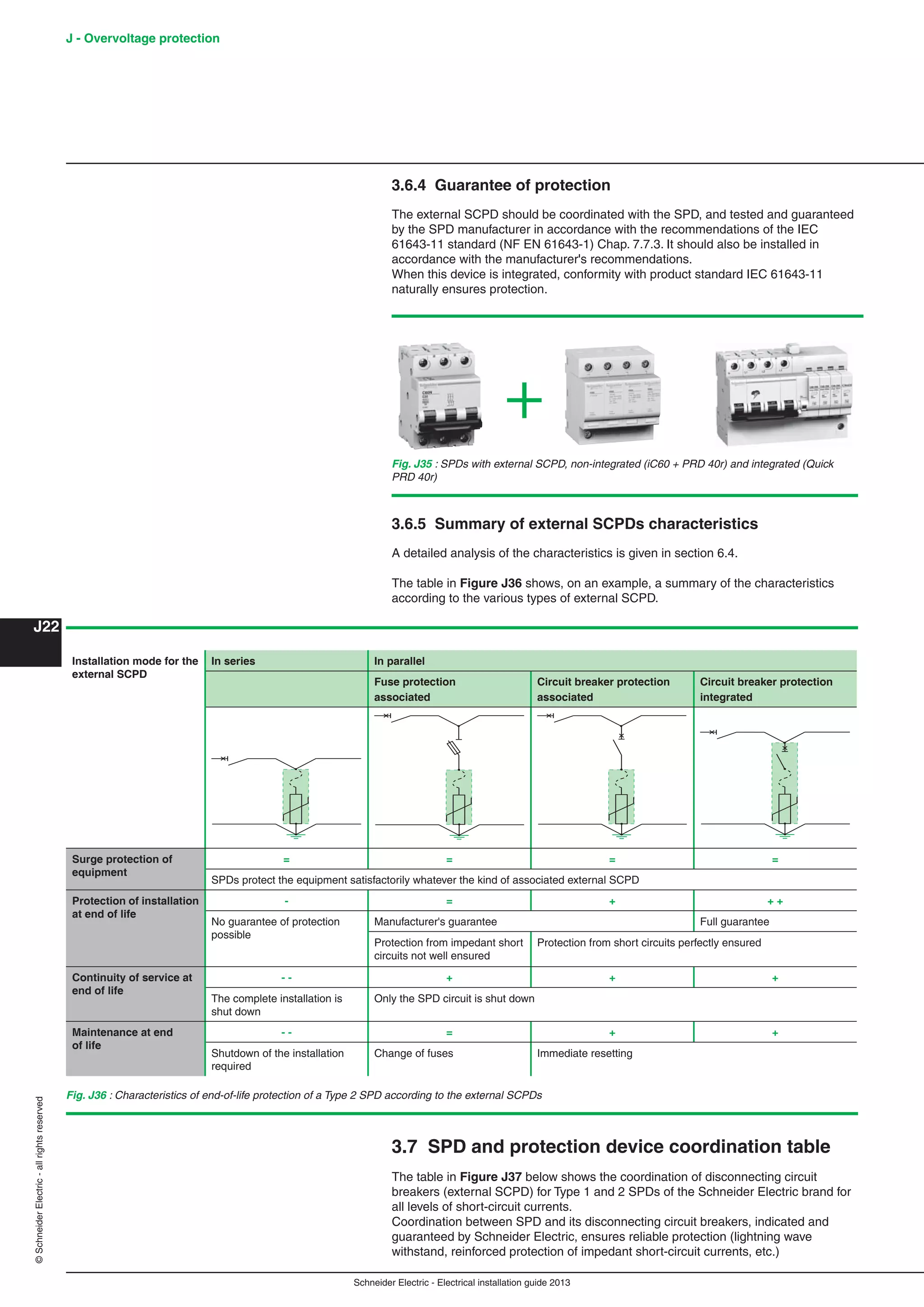
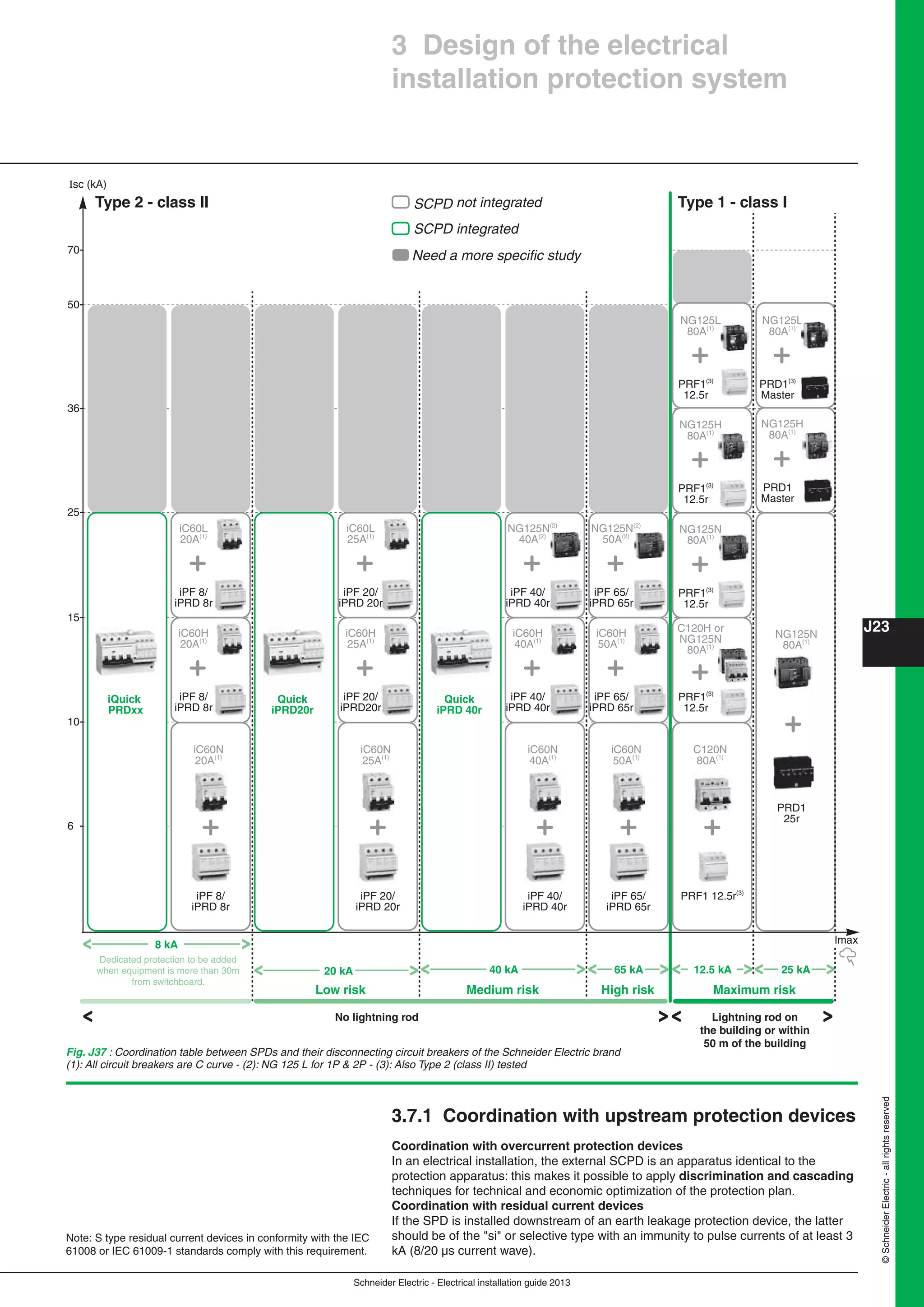
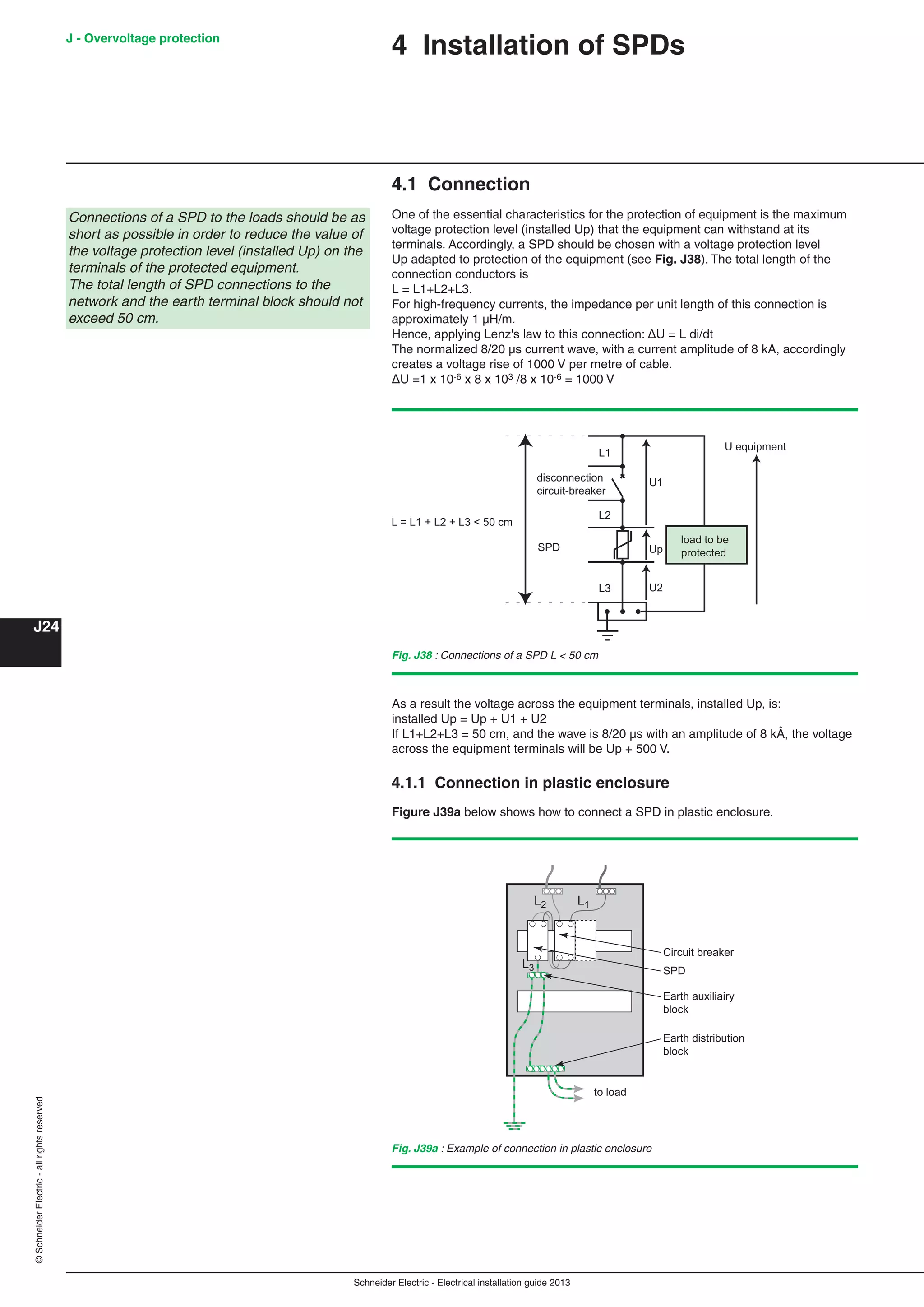
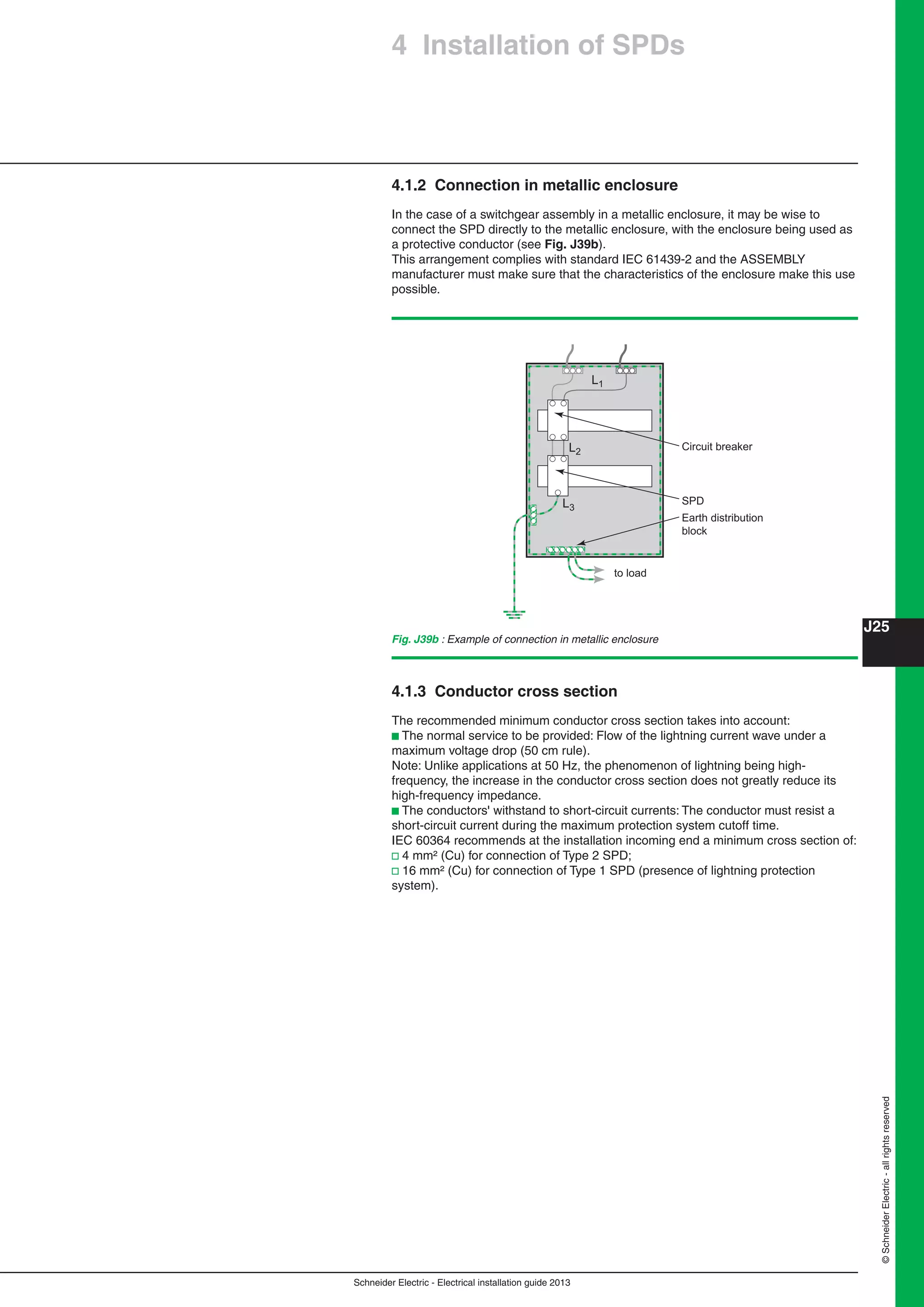
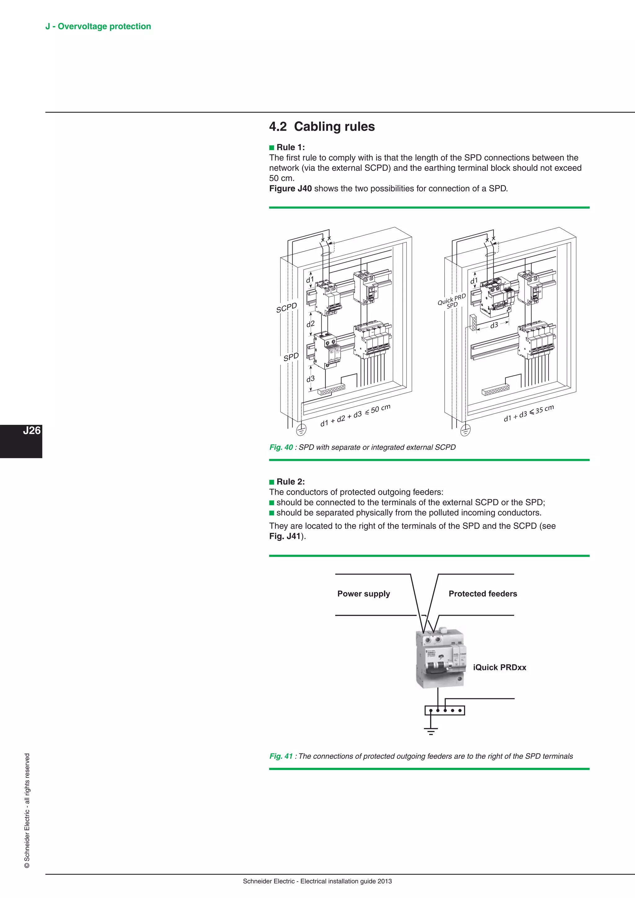
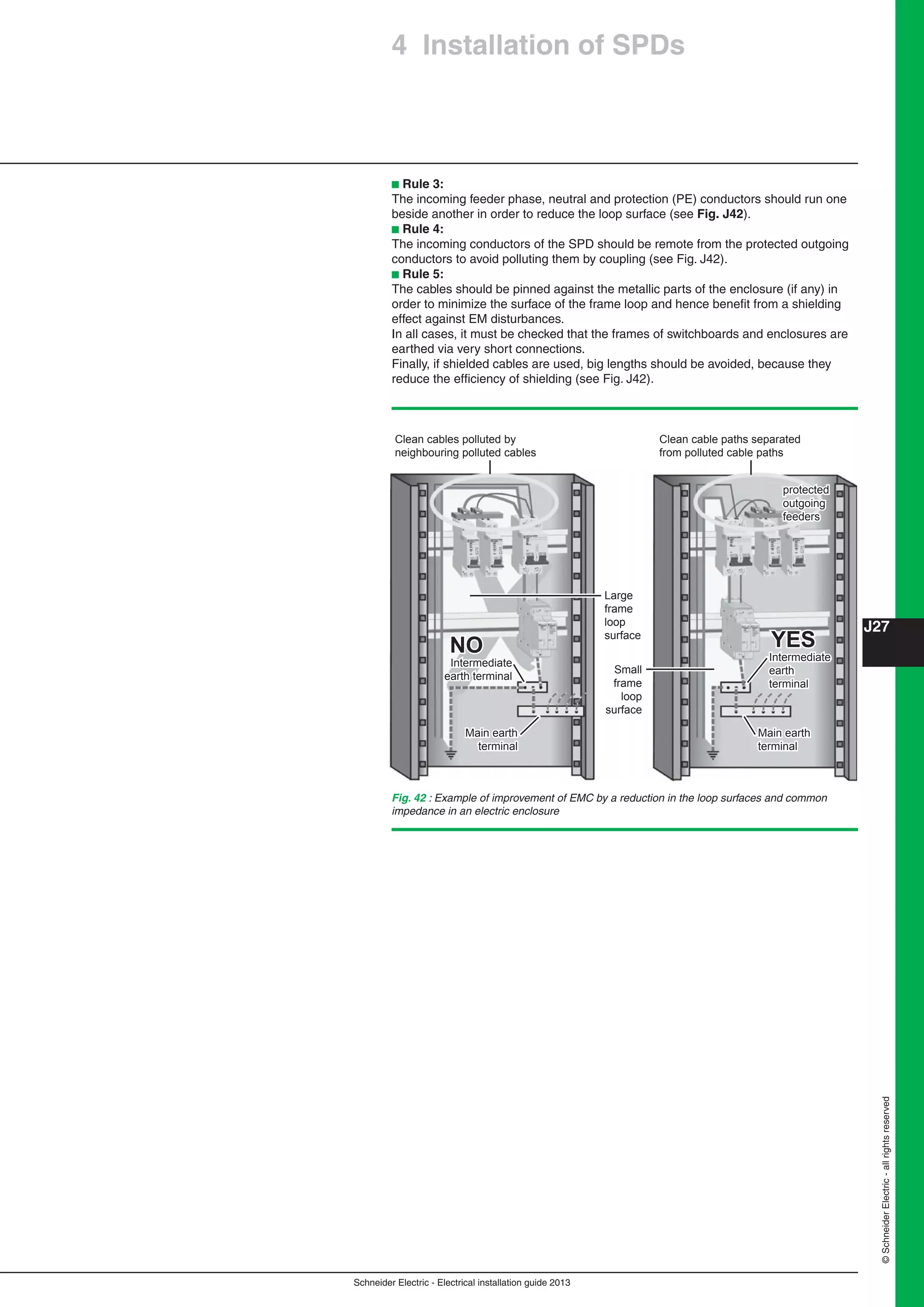
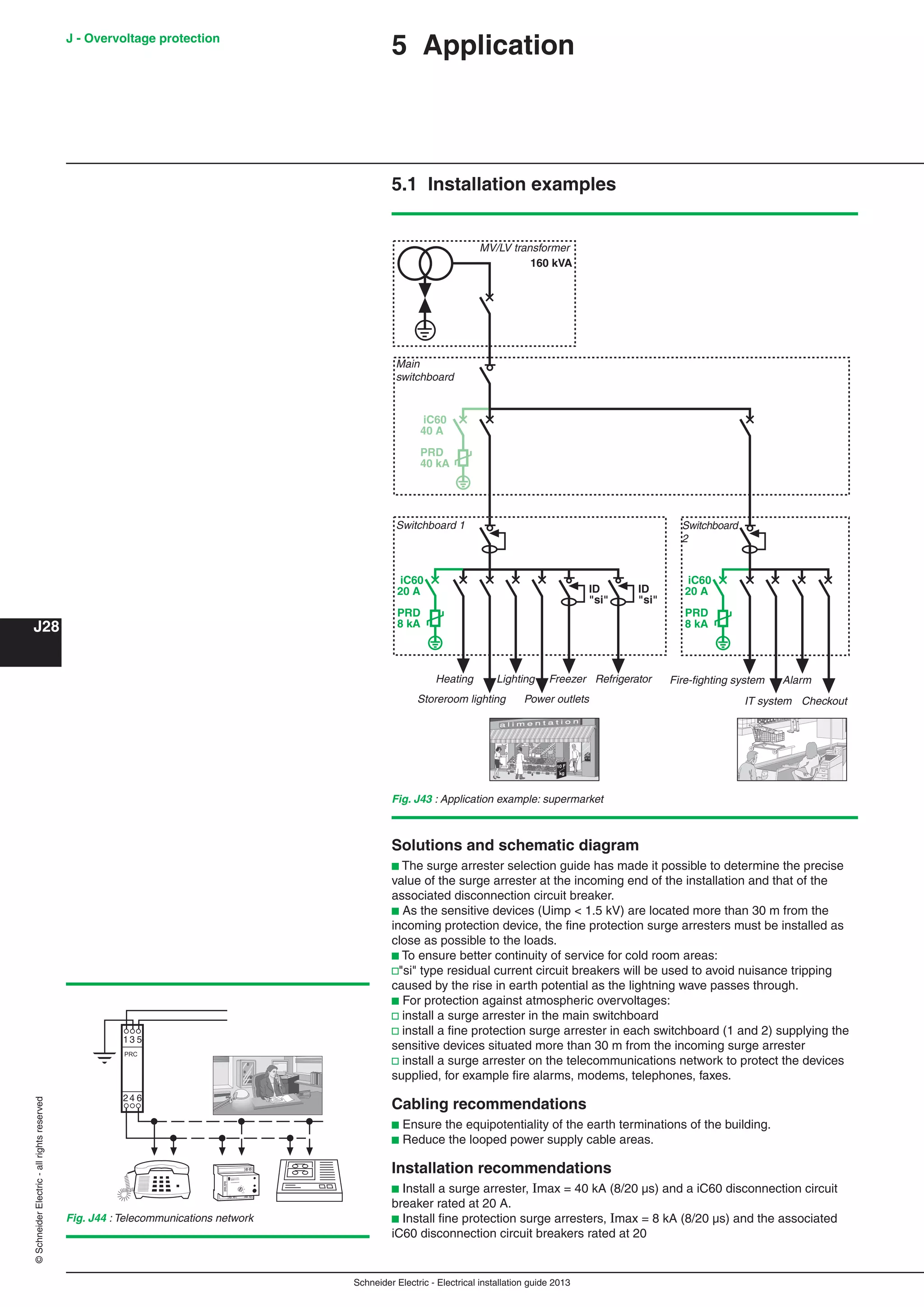
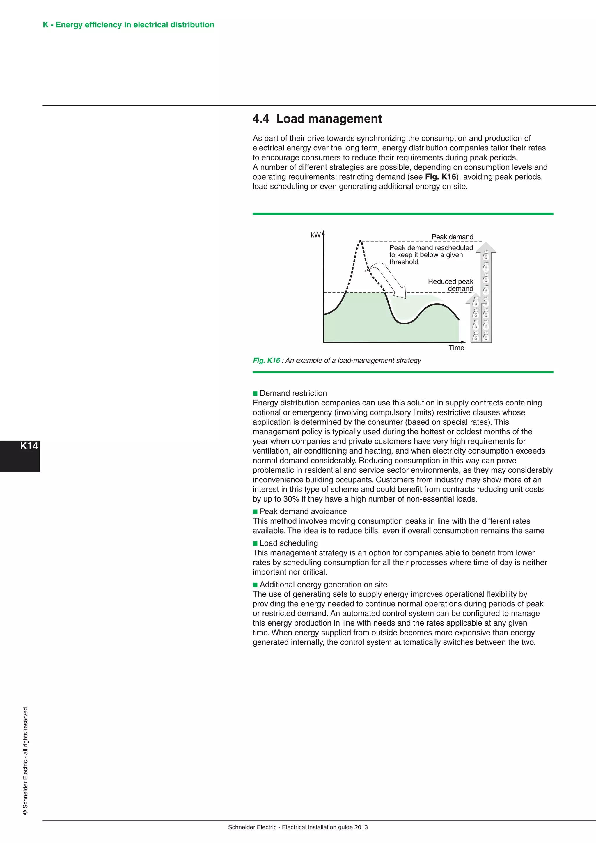
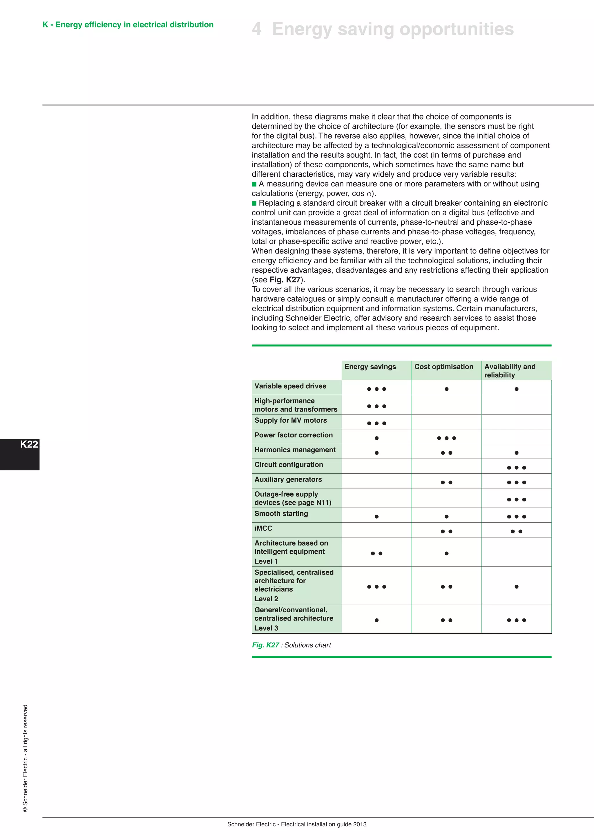
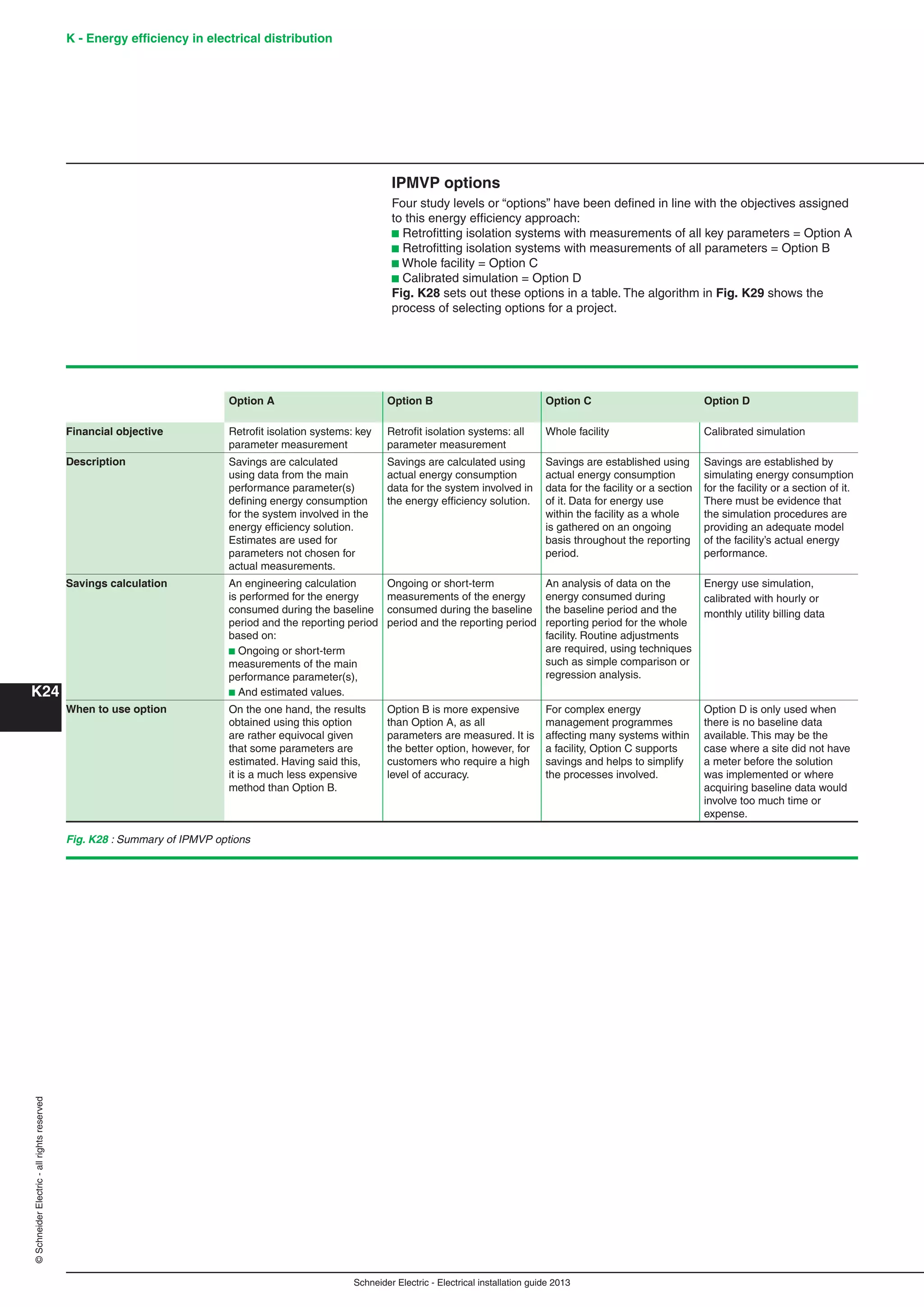
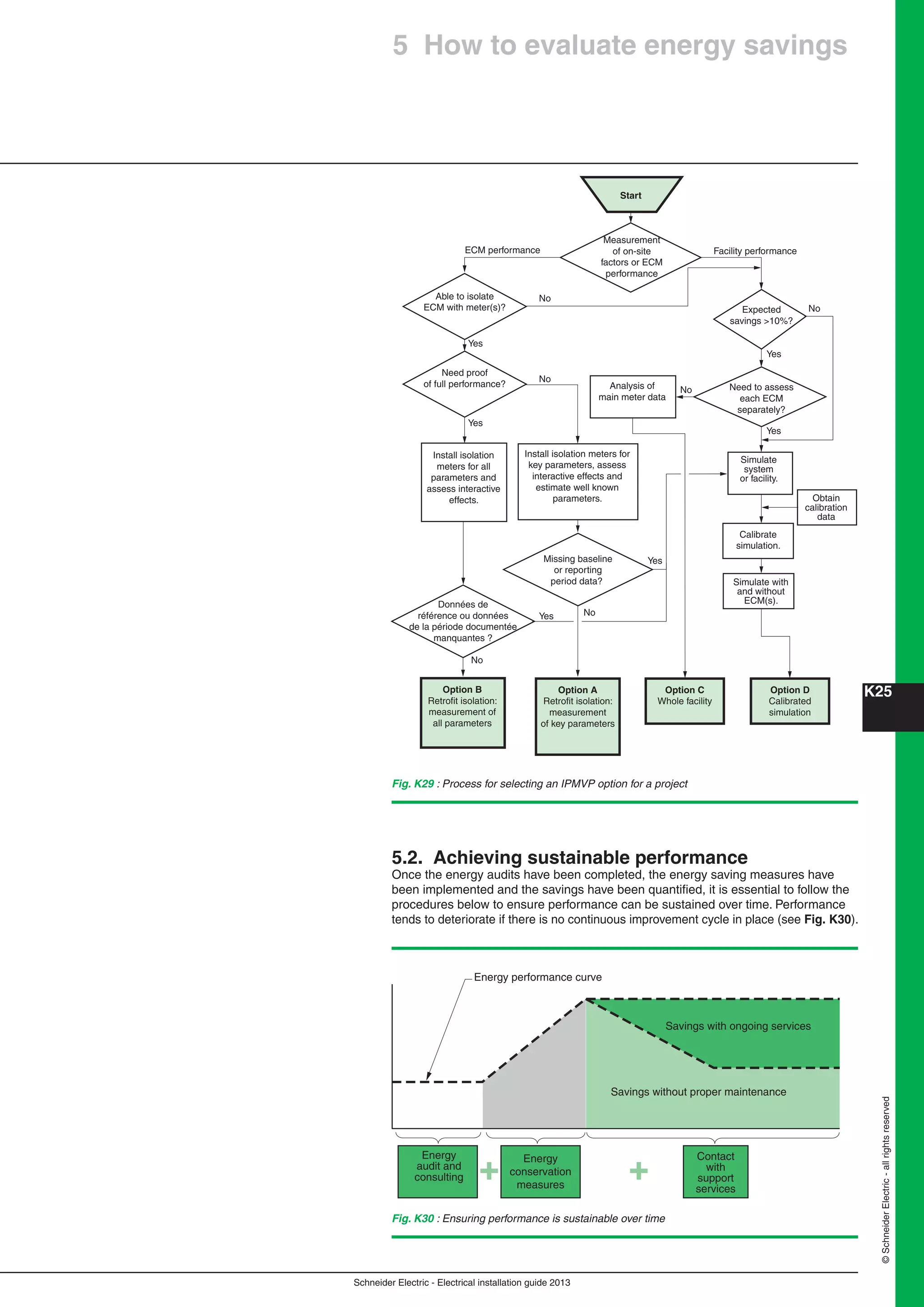
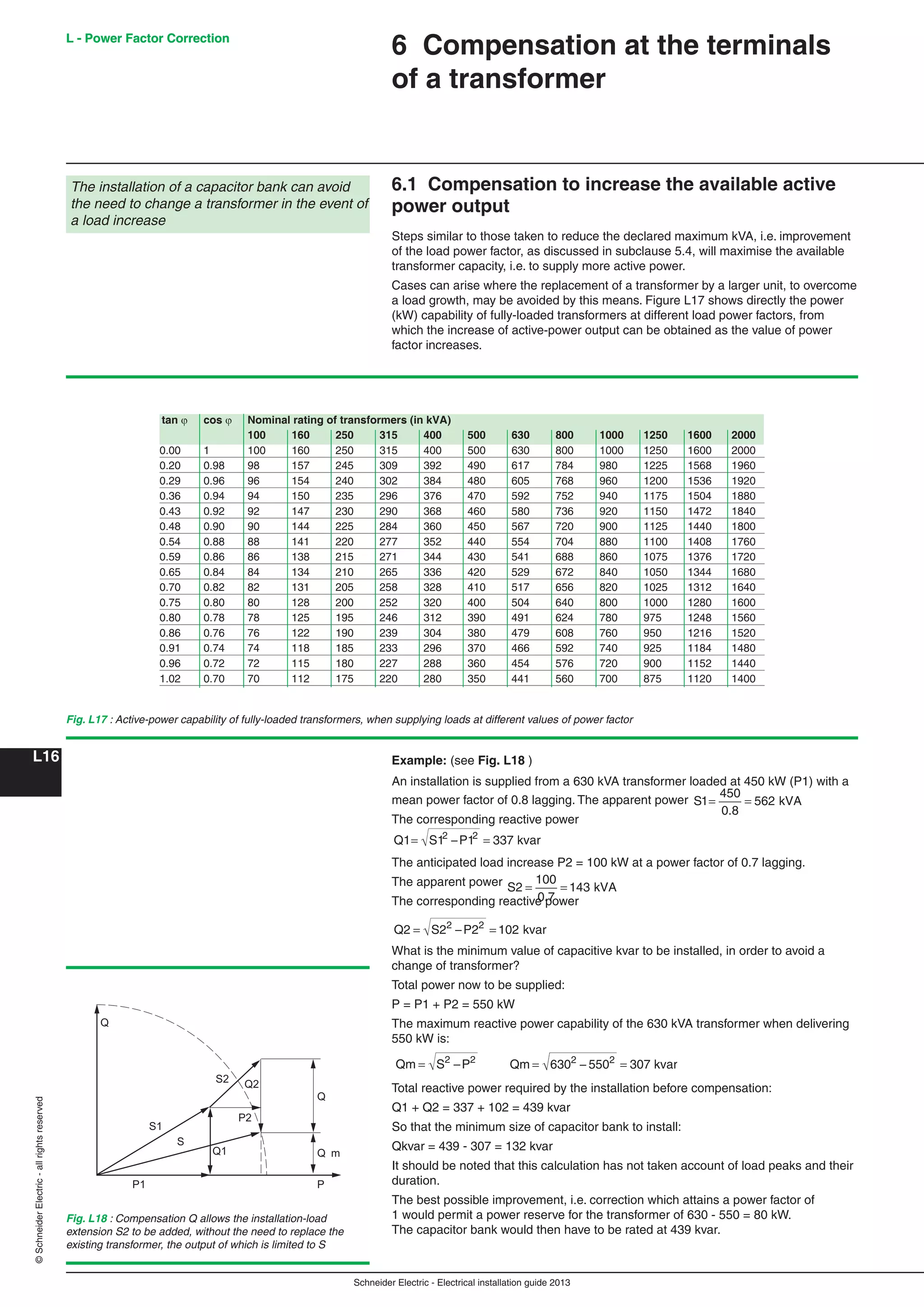
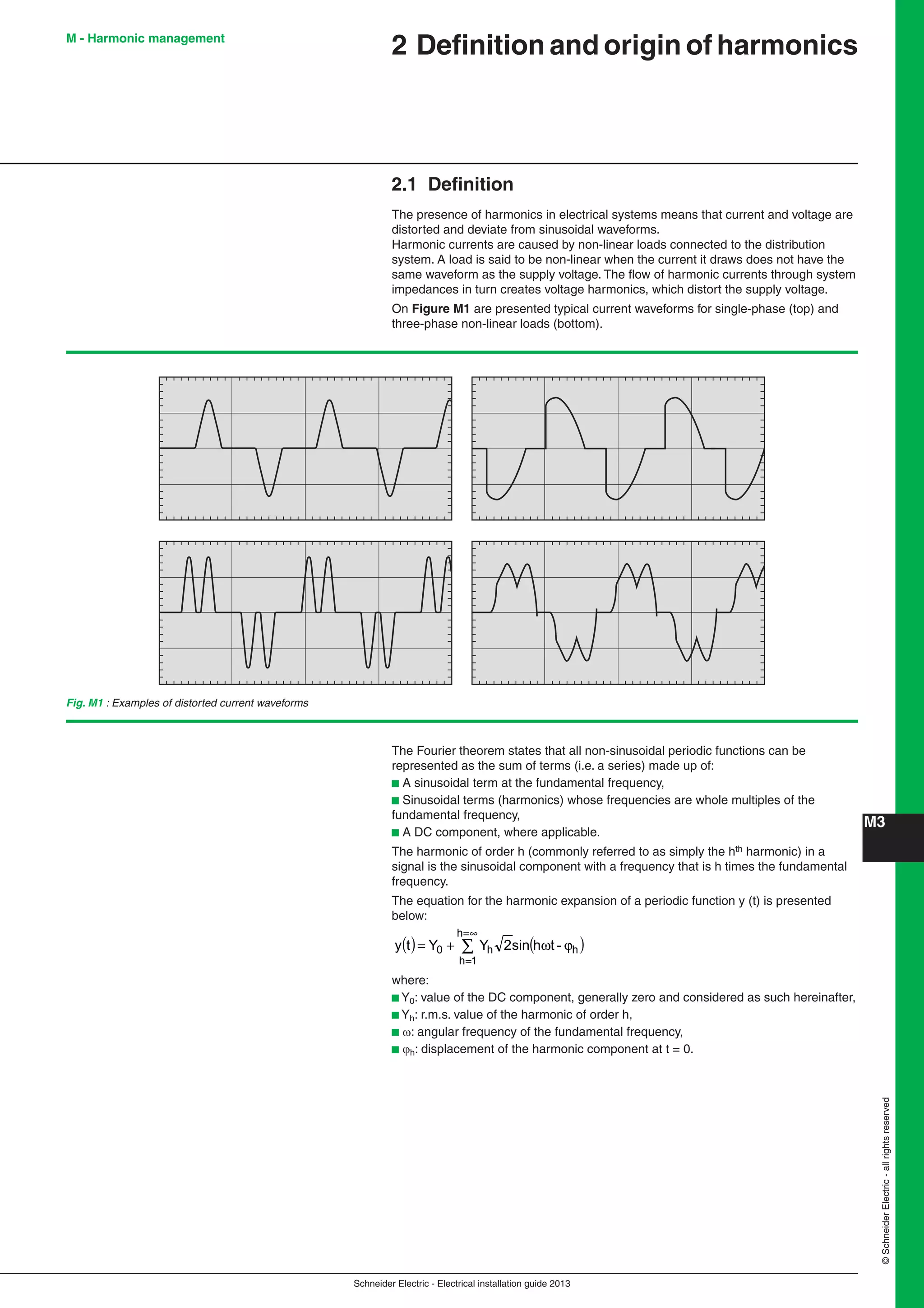
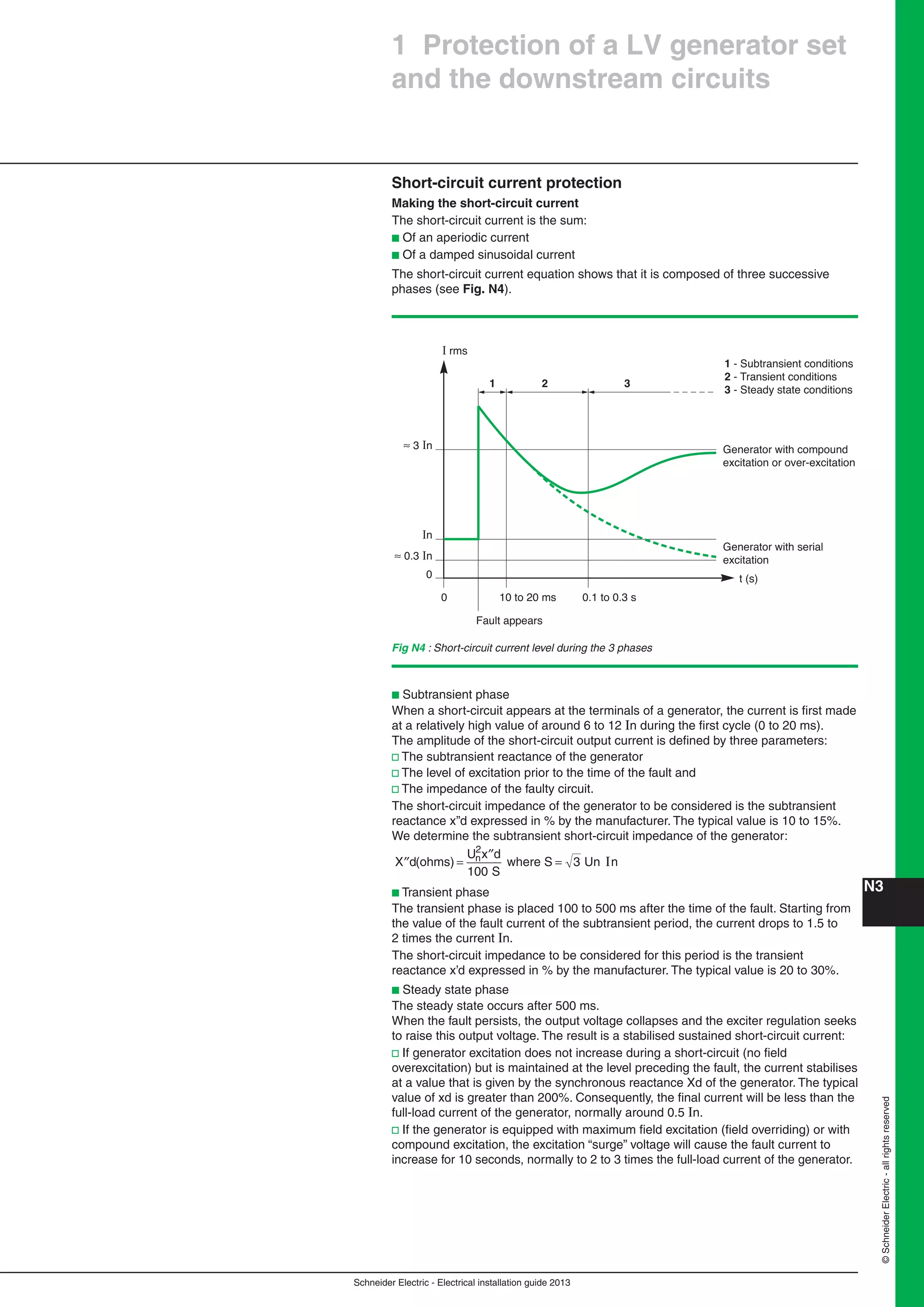
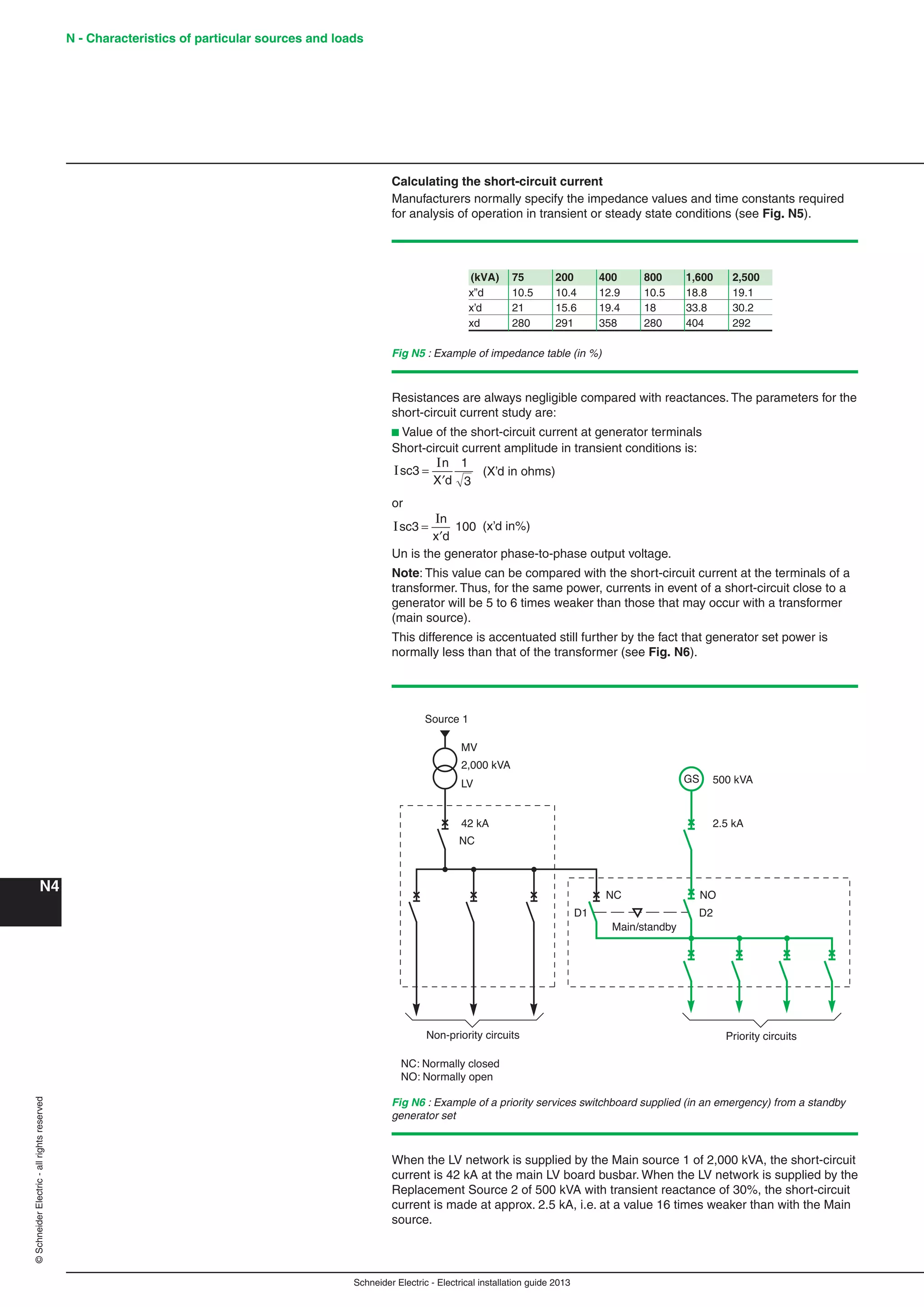
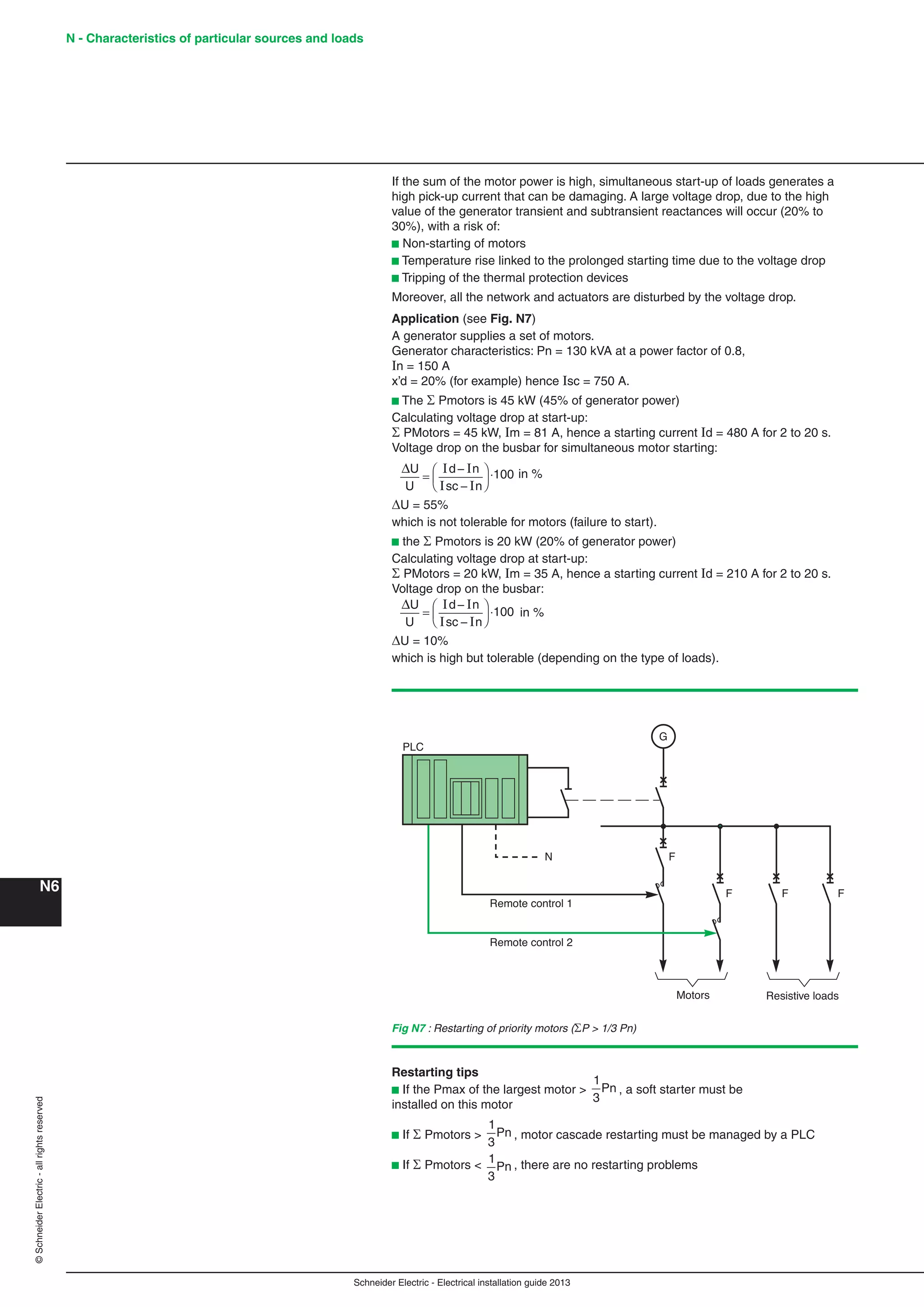
This chapter provides guidance on general rules for electrical installation design including methodology, rules and regulations, load characteristics, and power loading considerations. Designers should follow the order of chapters, which begins with understanding applicable standards and regulations. Key factors include voltage ranges, safety testing, periodic inspections, equipment certification, and environmental conditions. Load characteristics such as motors and heating loads are also addressed. Power loading calculations cover installed power, demand, diversity factors, and sizing of transformers and power sources.


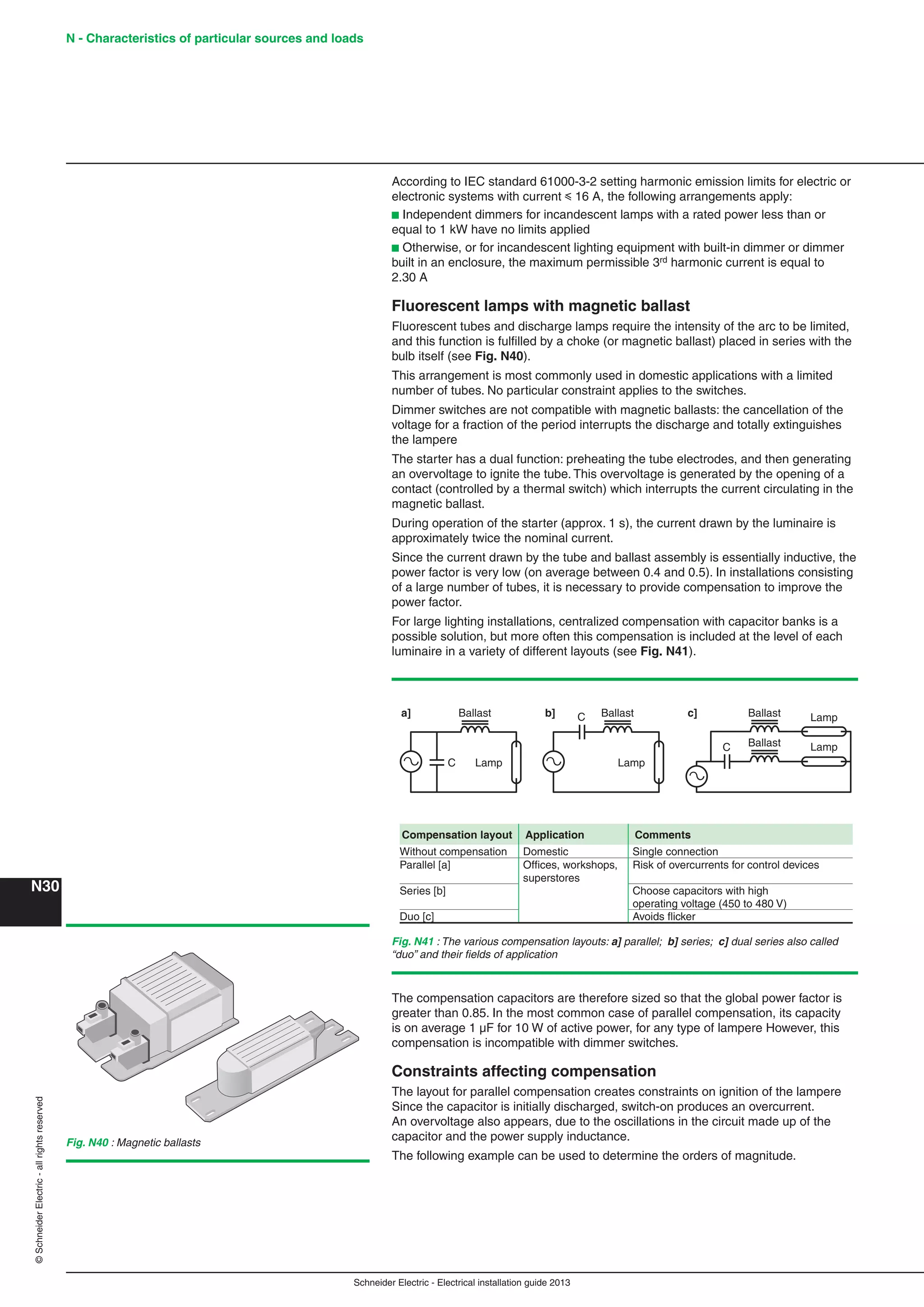
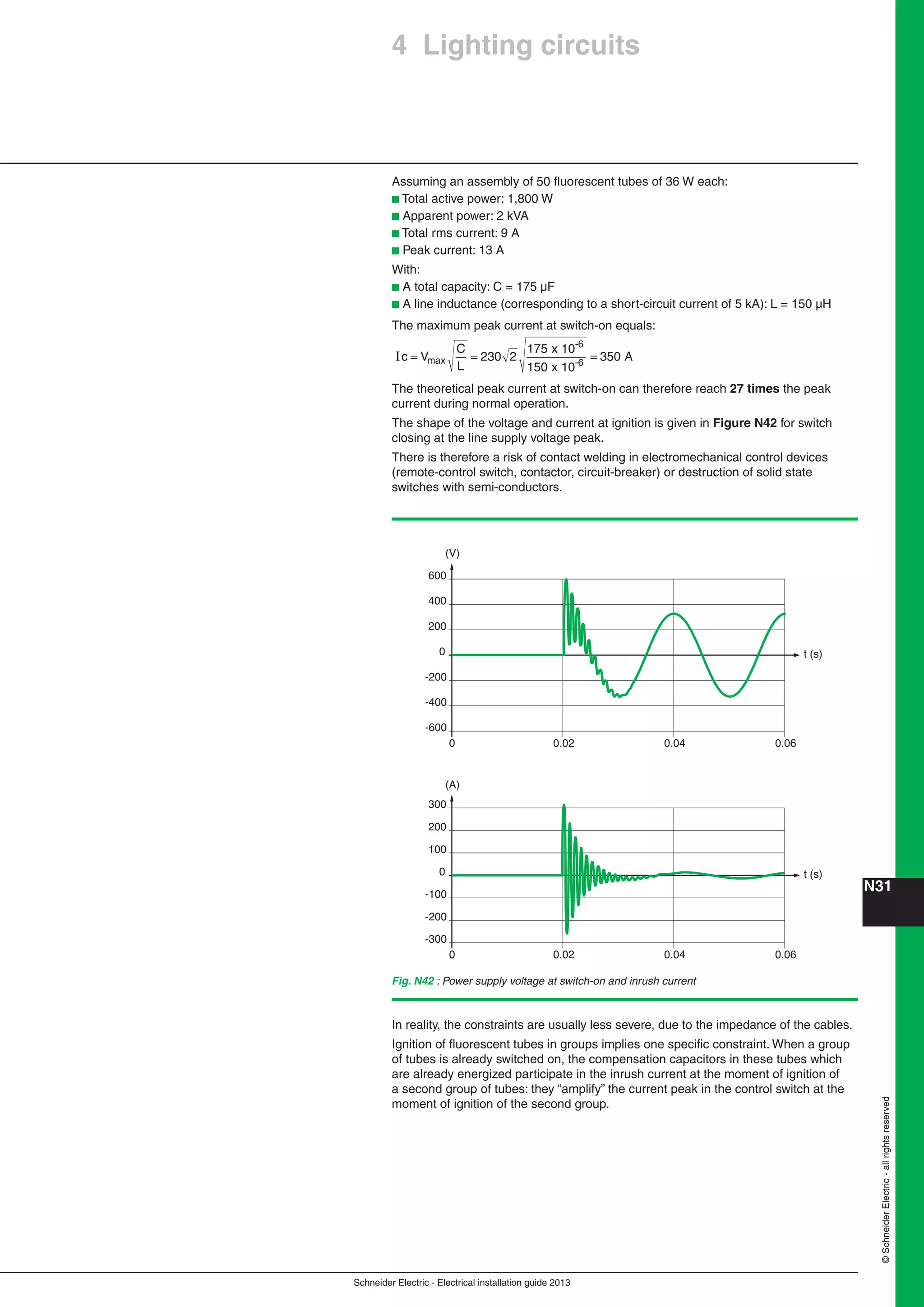
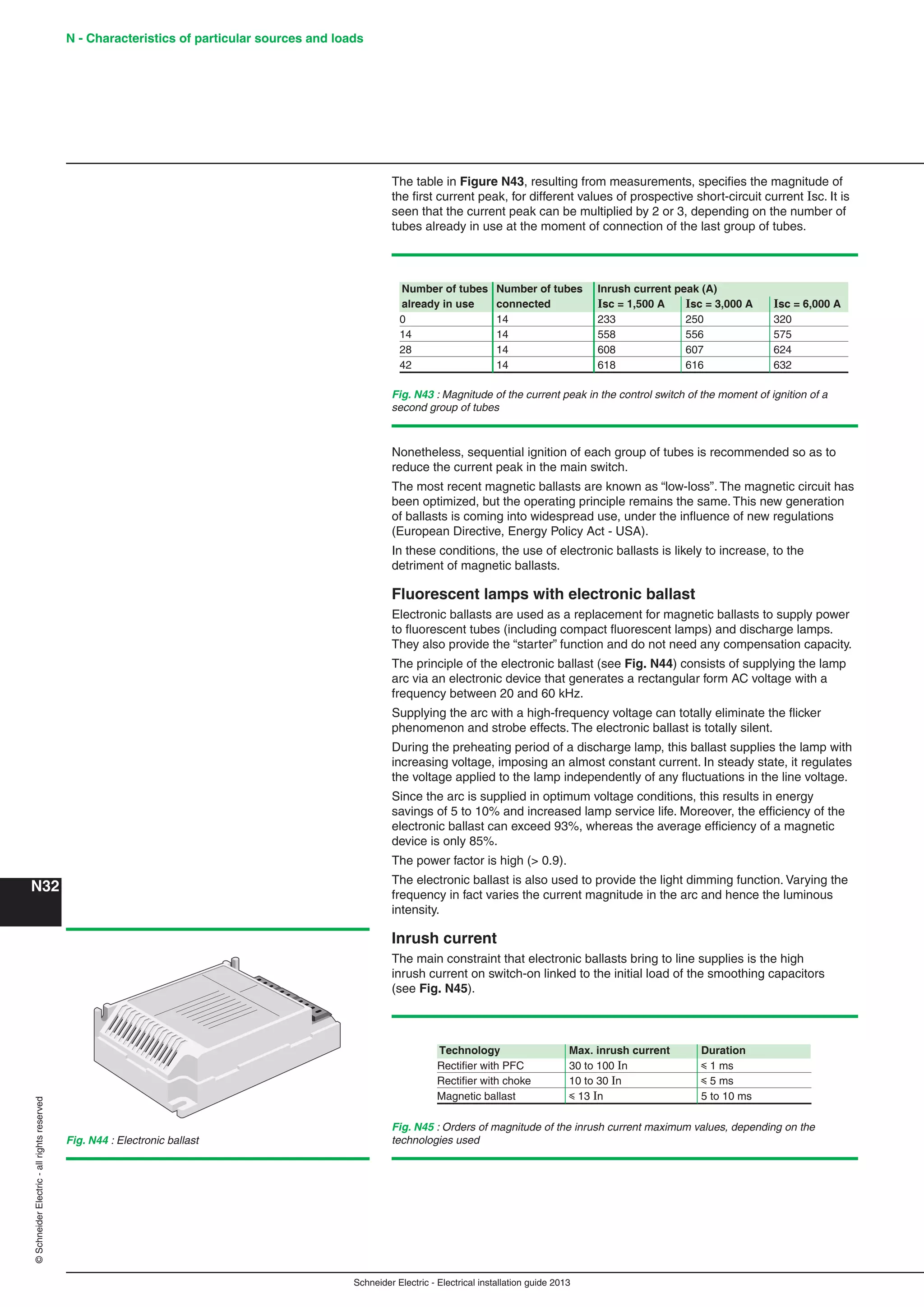
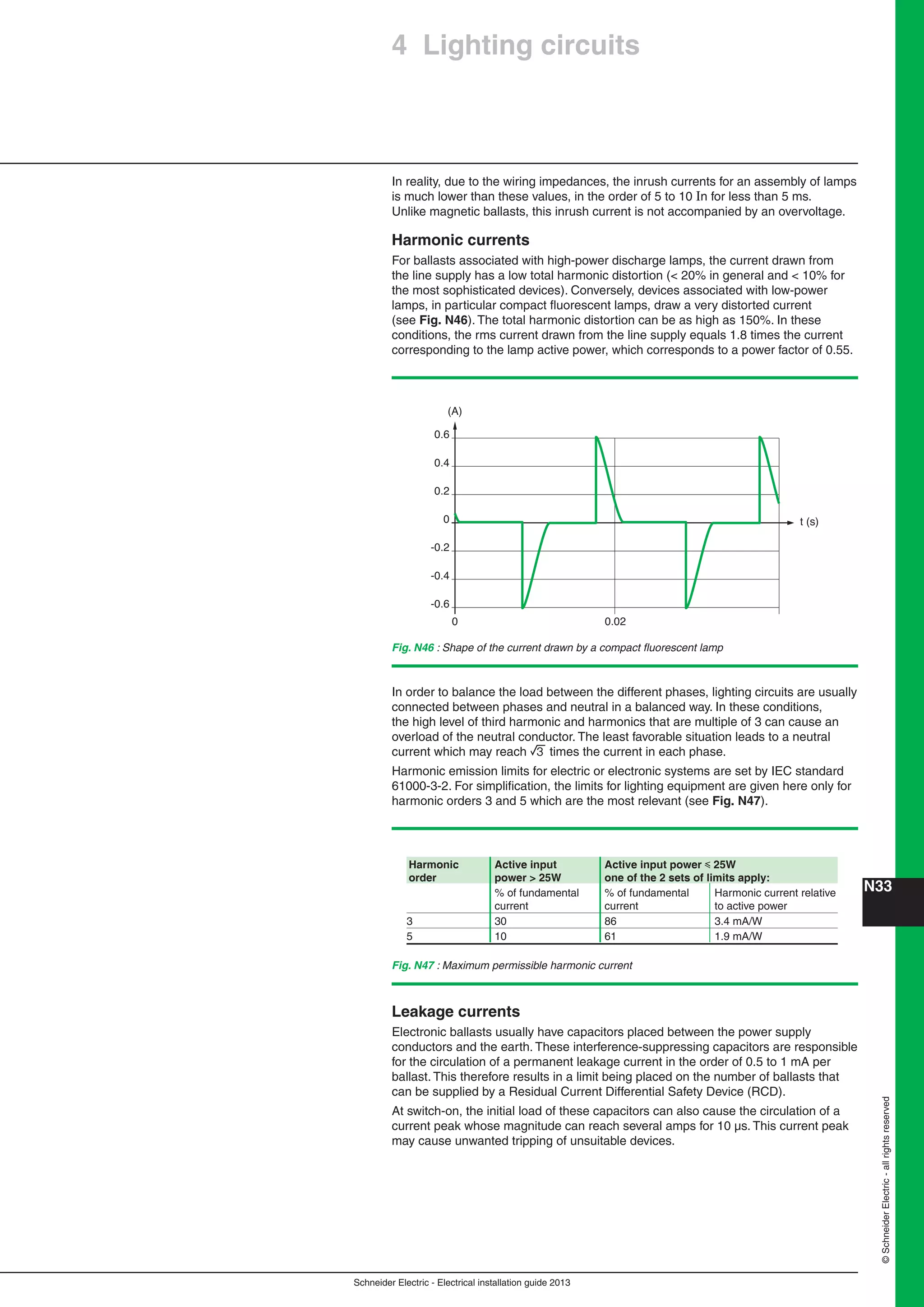
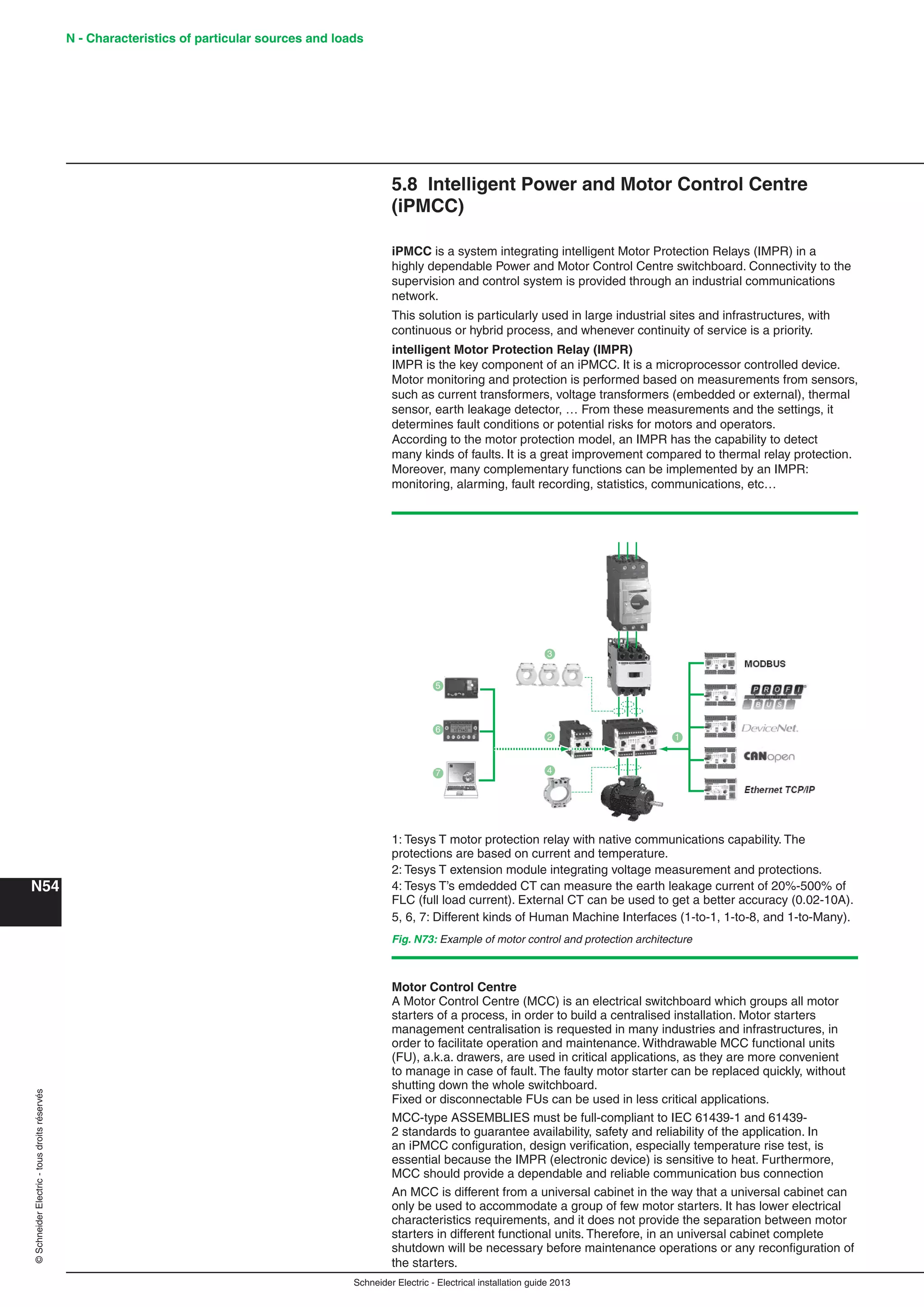
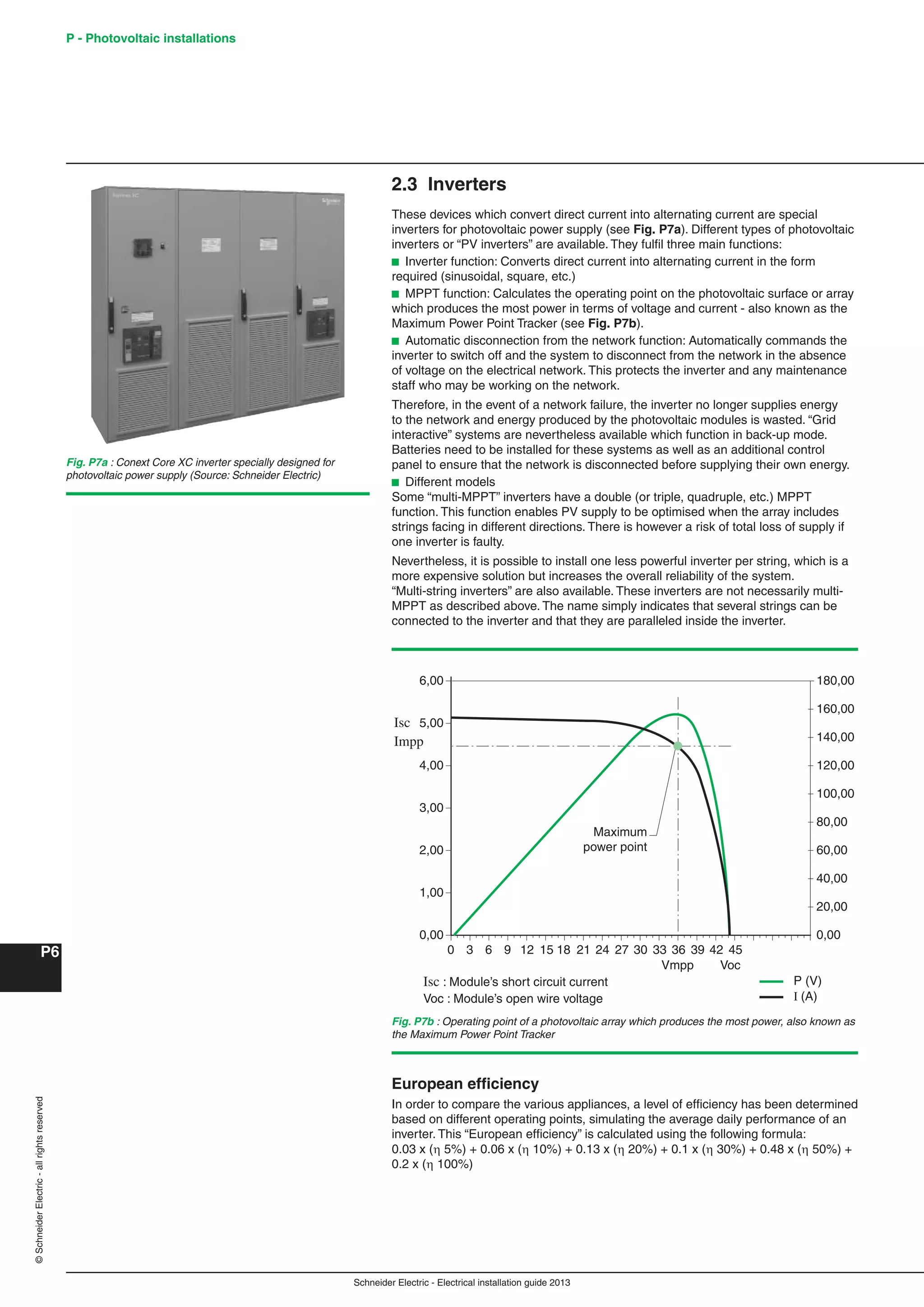
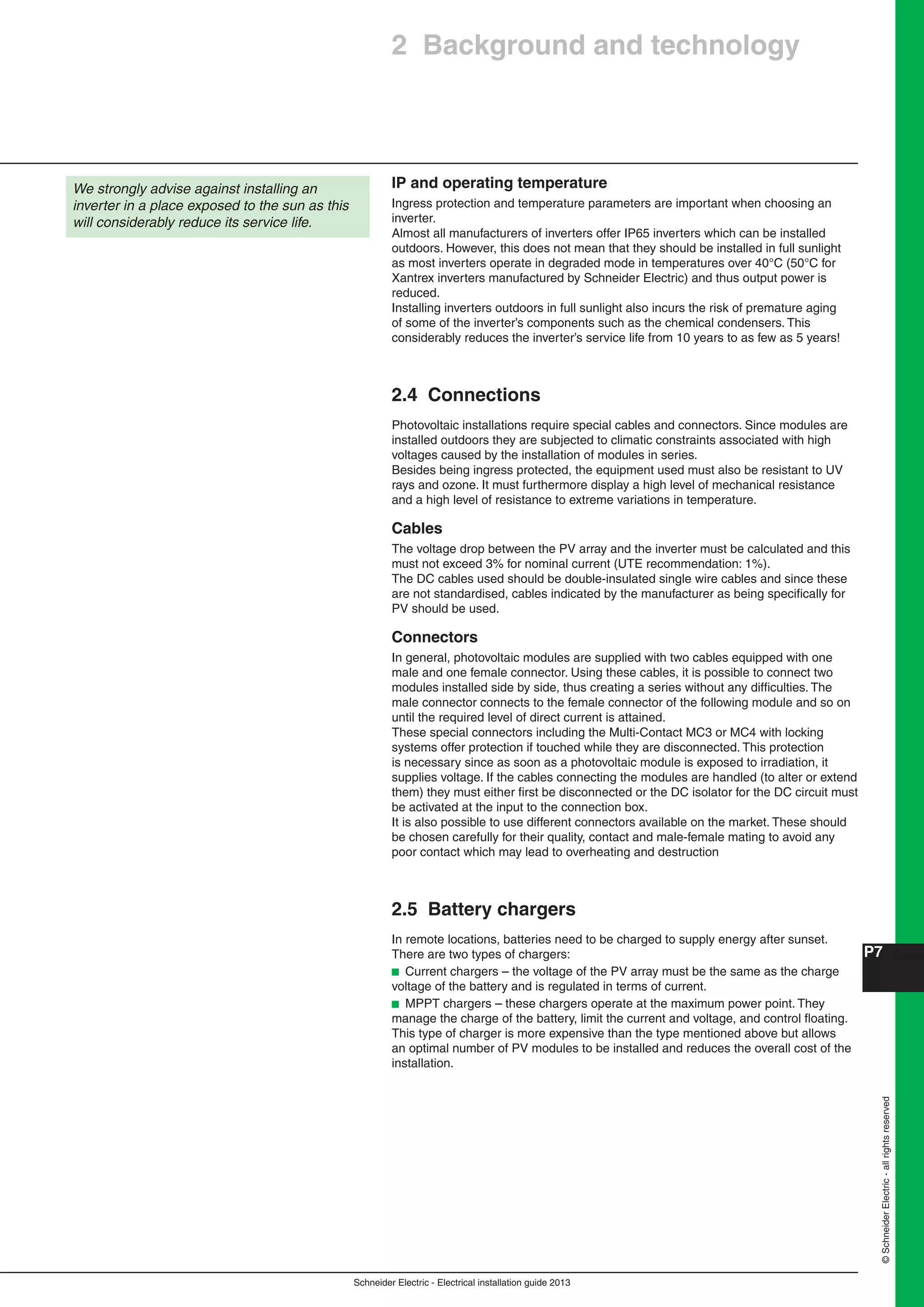
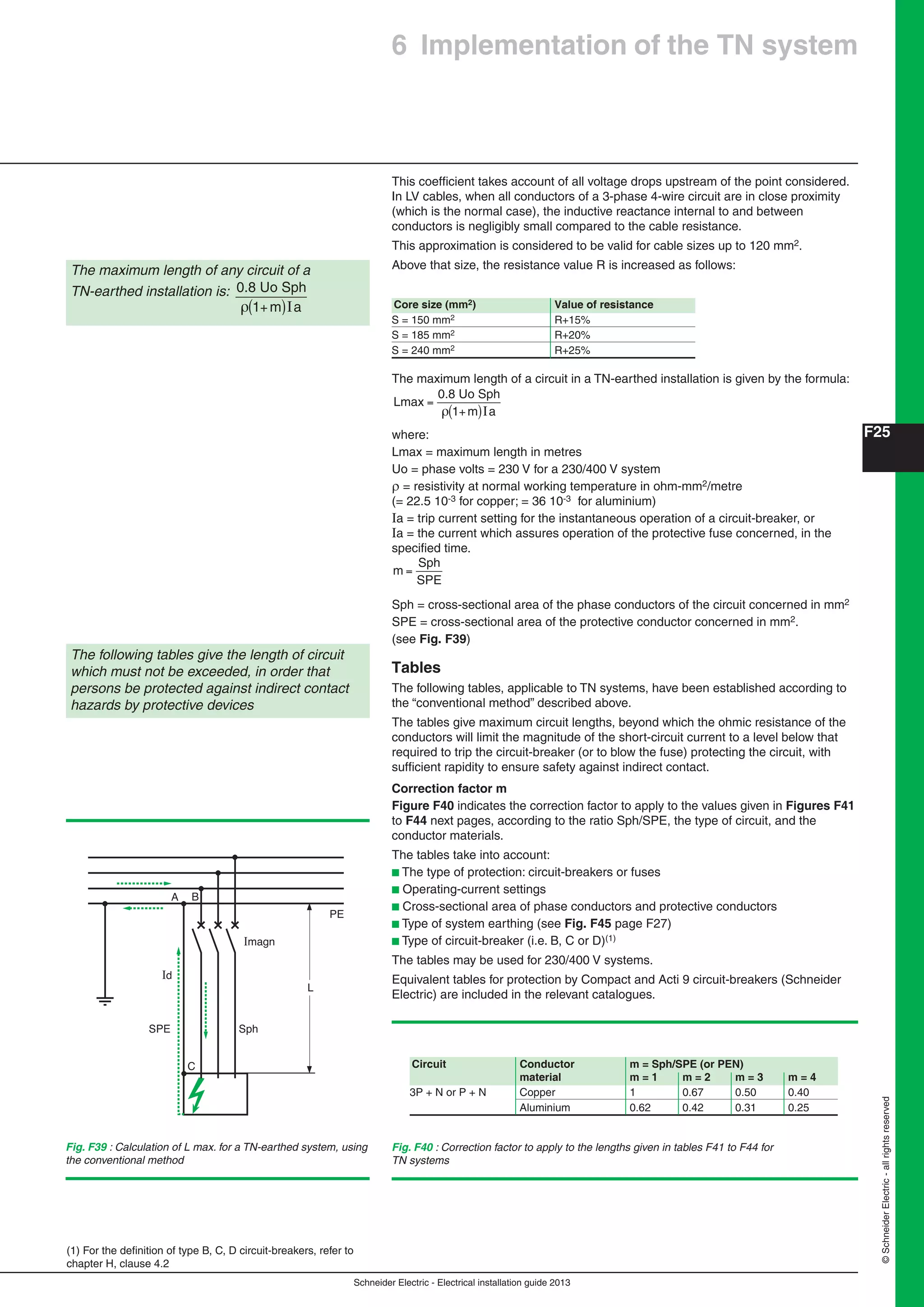
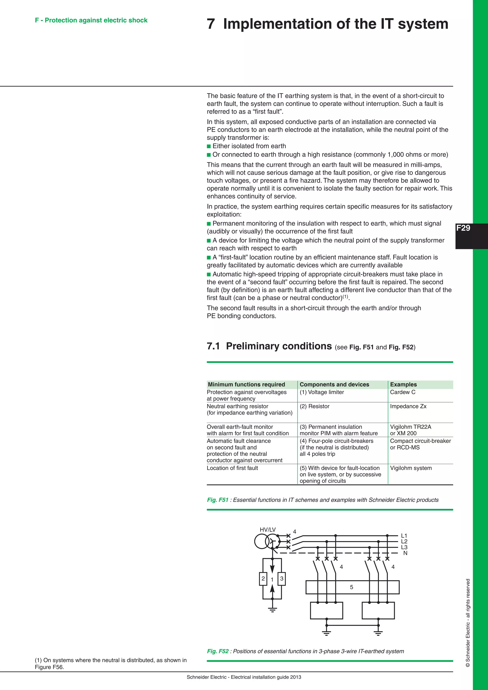
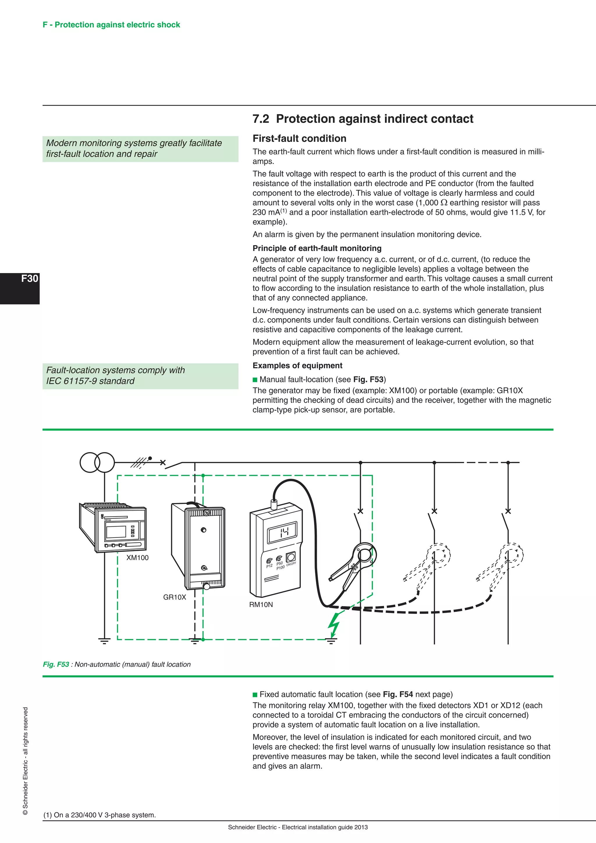
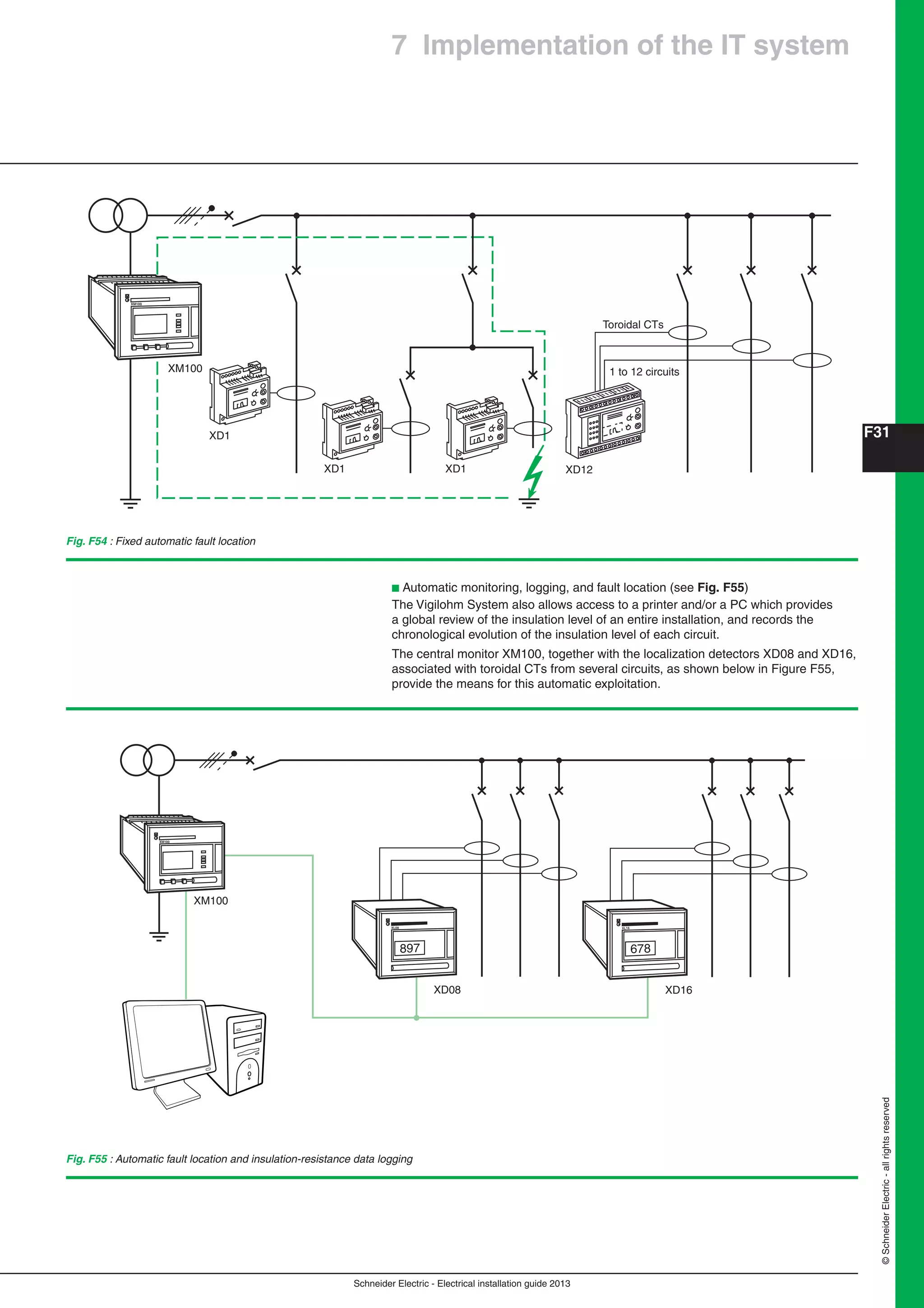
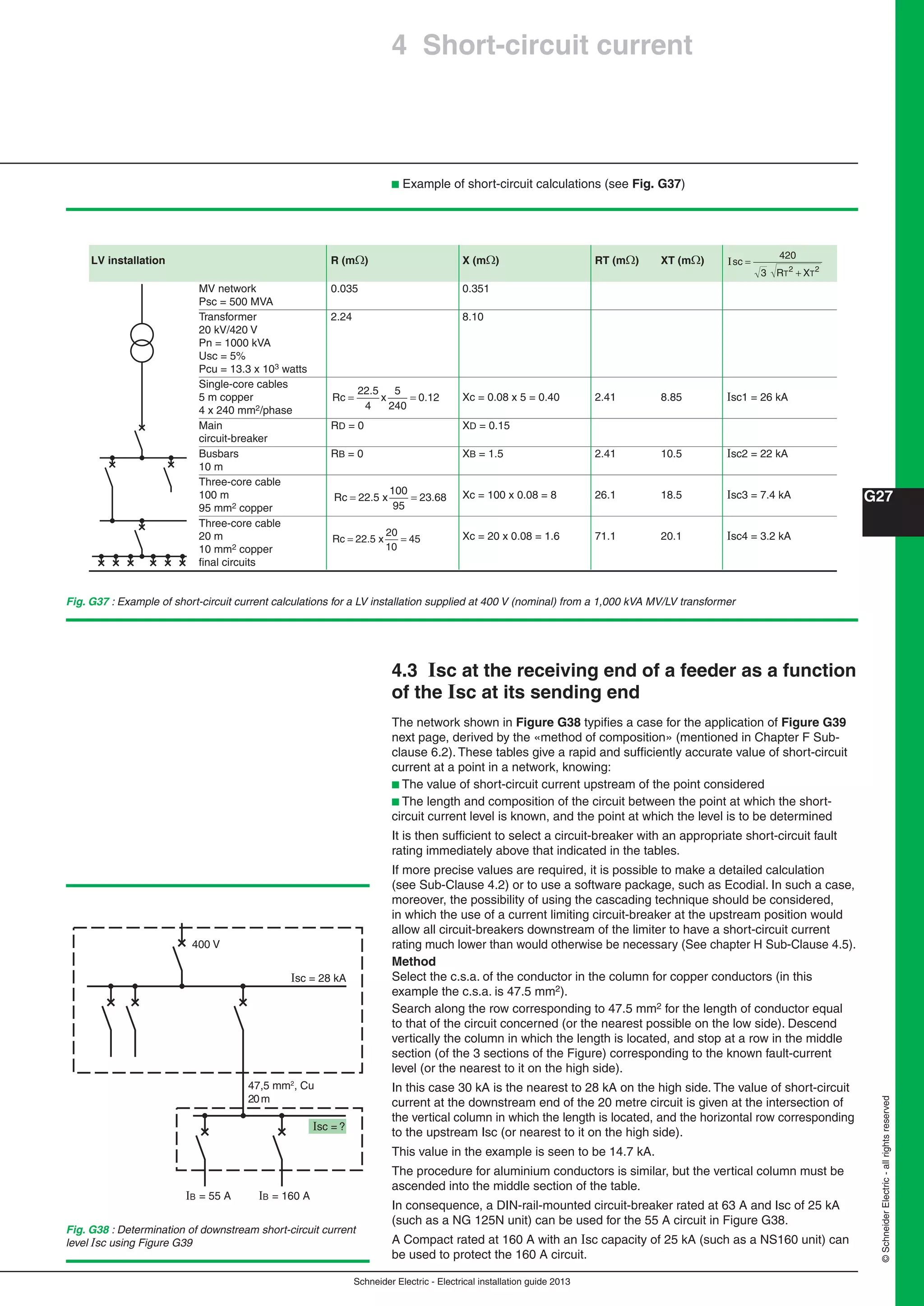
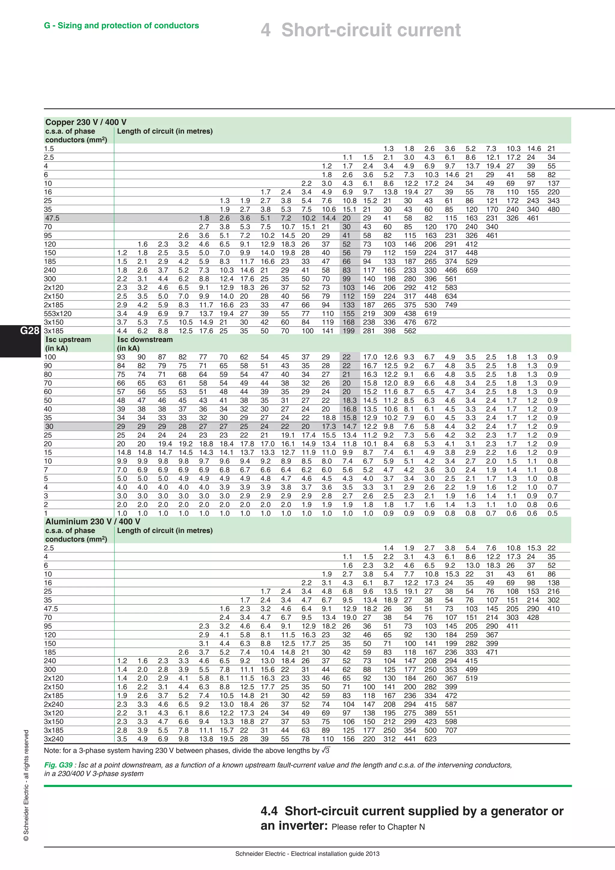
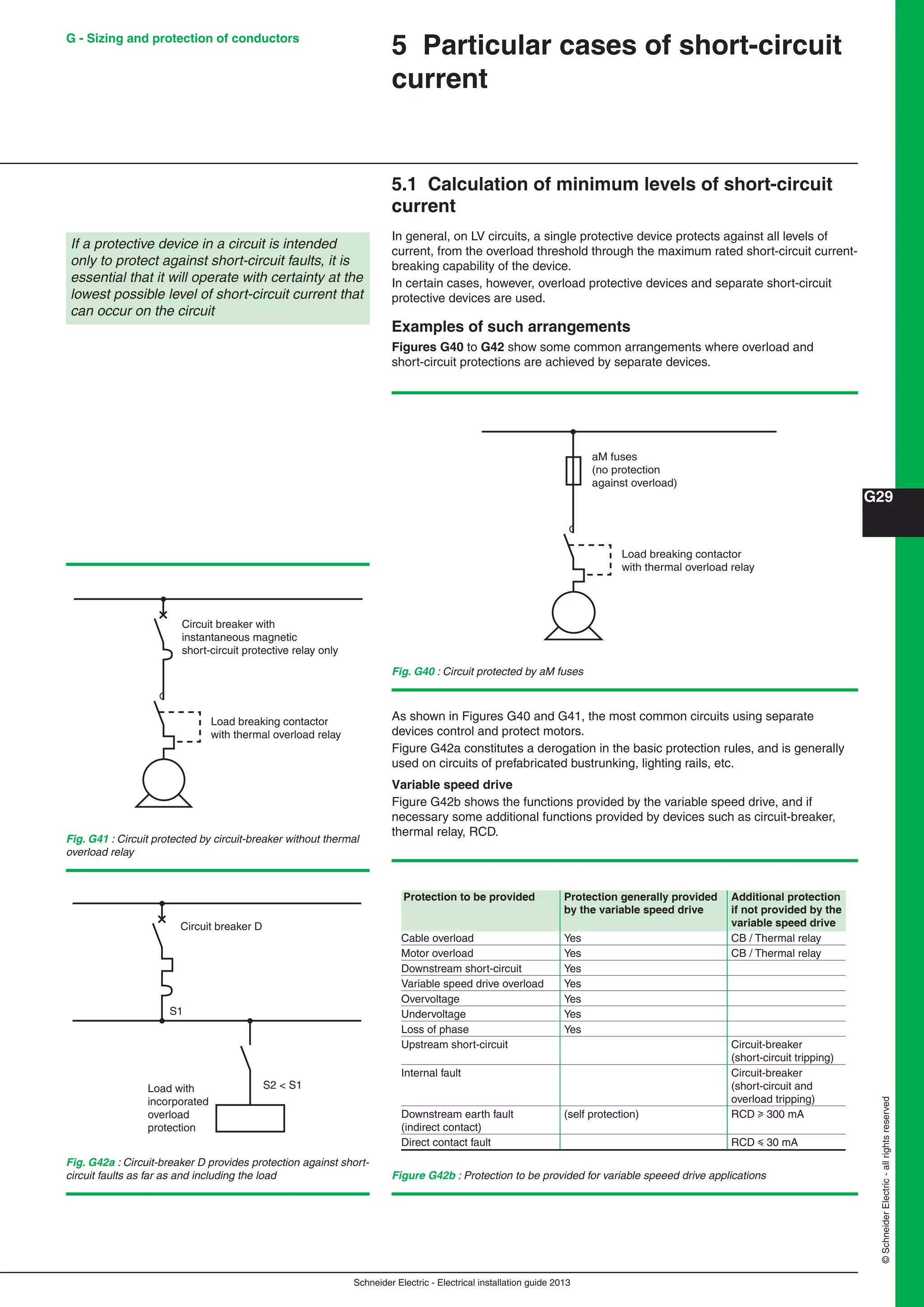
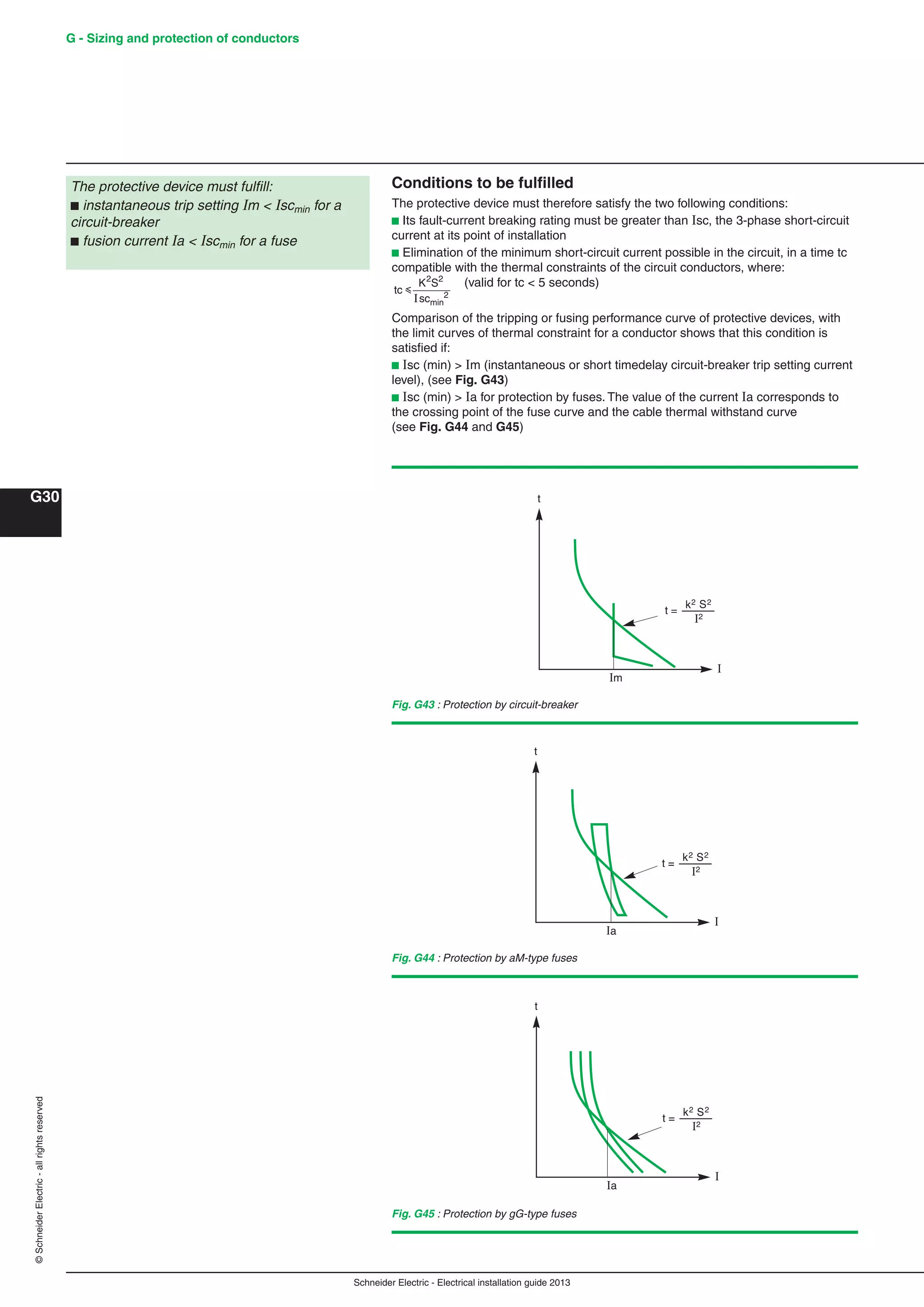
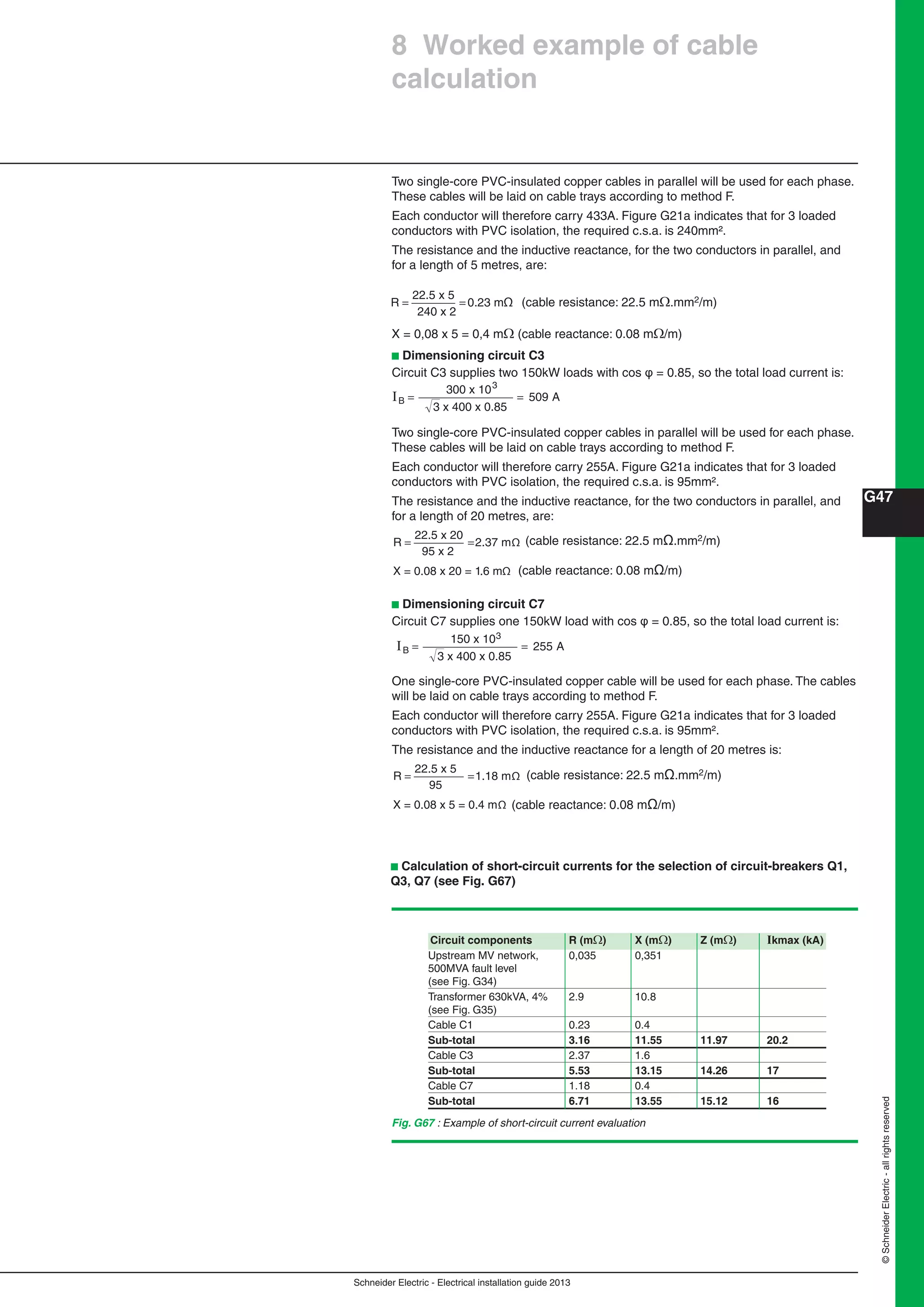
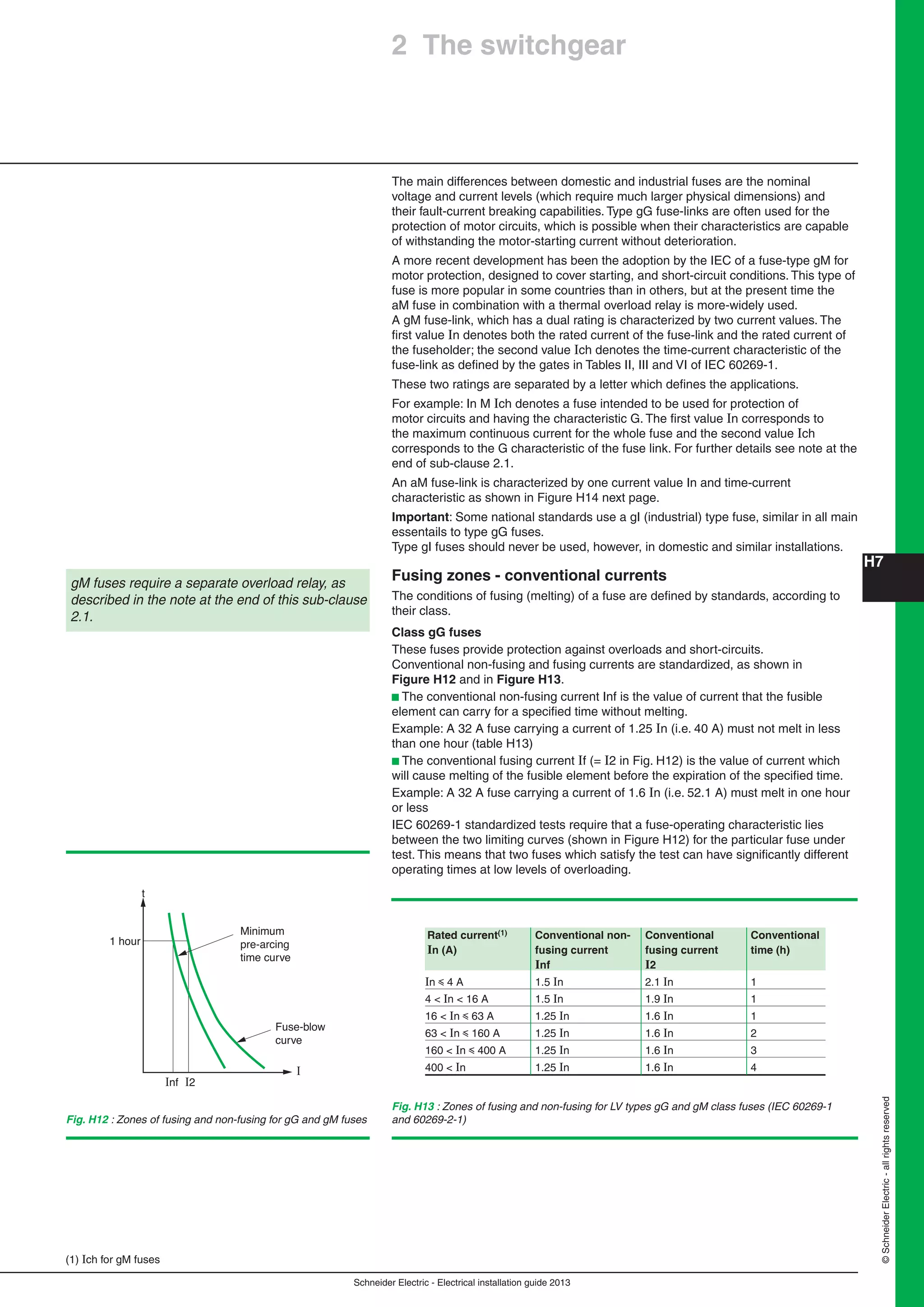
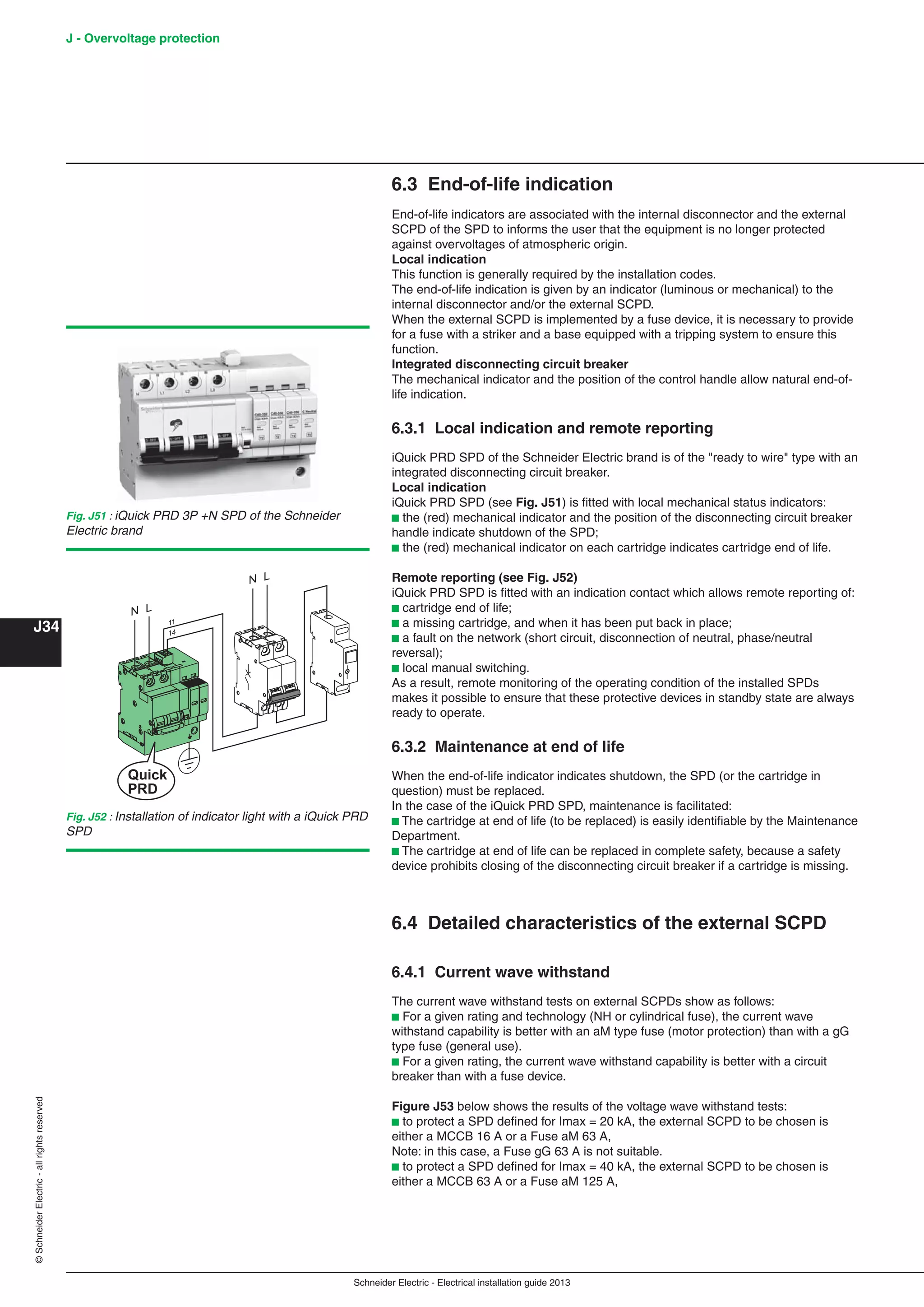
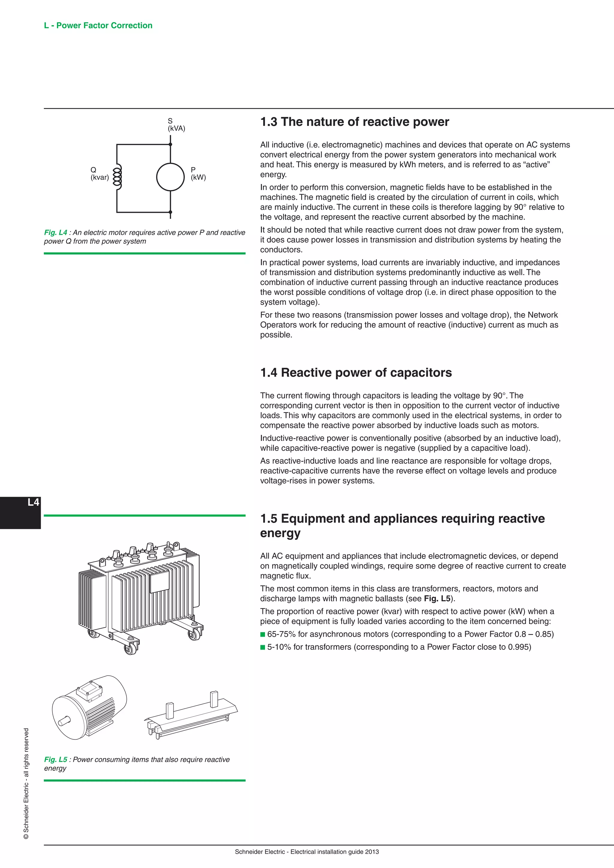
![Schneider Electric - Electrical installation guide 2013
B - Connection to the MV utility
distribution network
B20
©SchneiderElectric-allrightsreserved
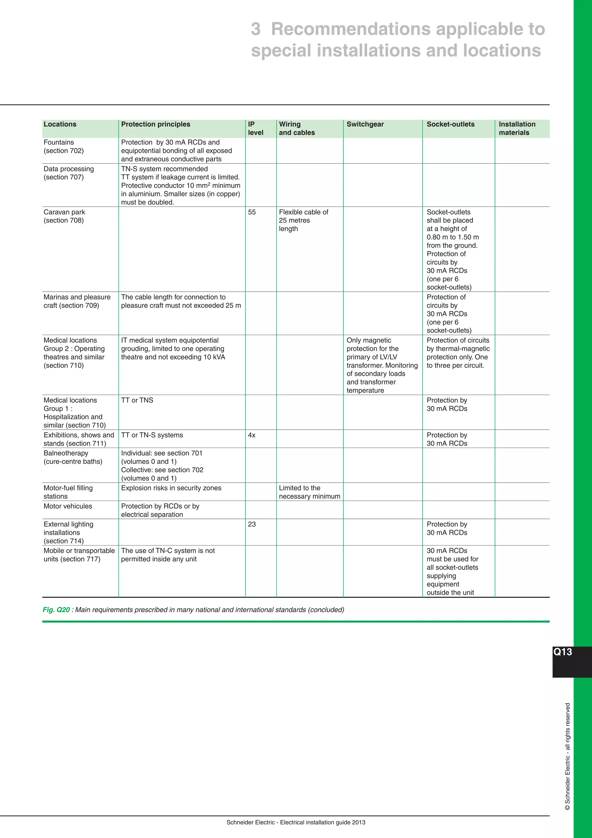
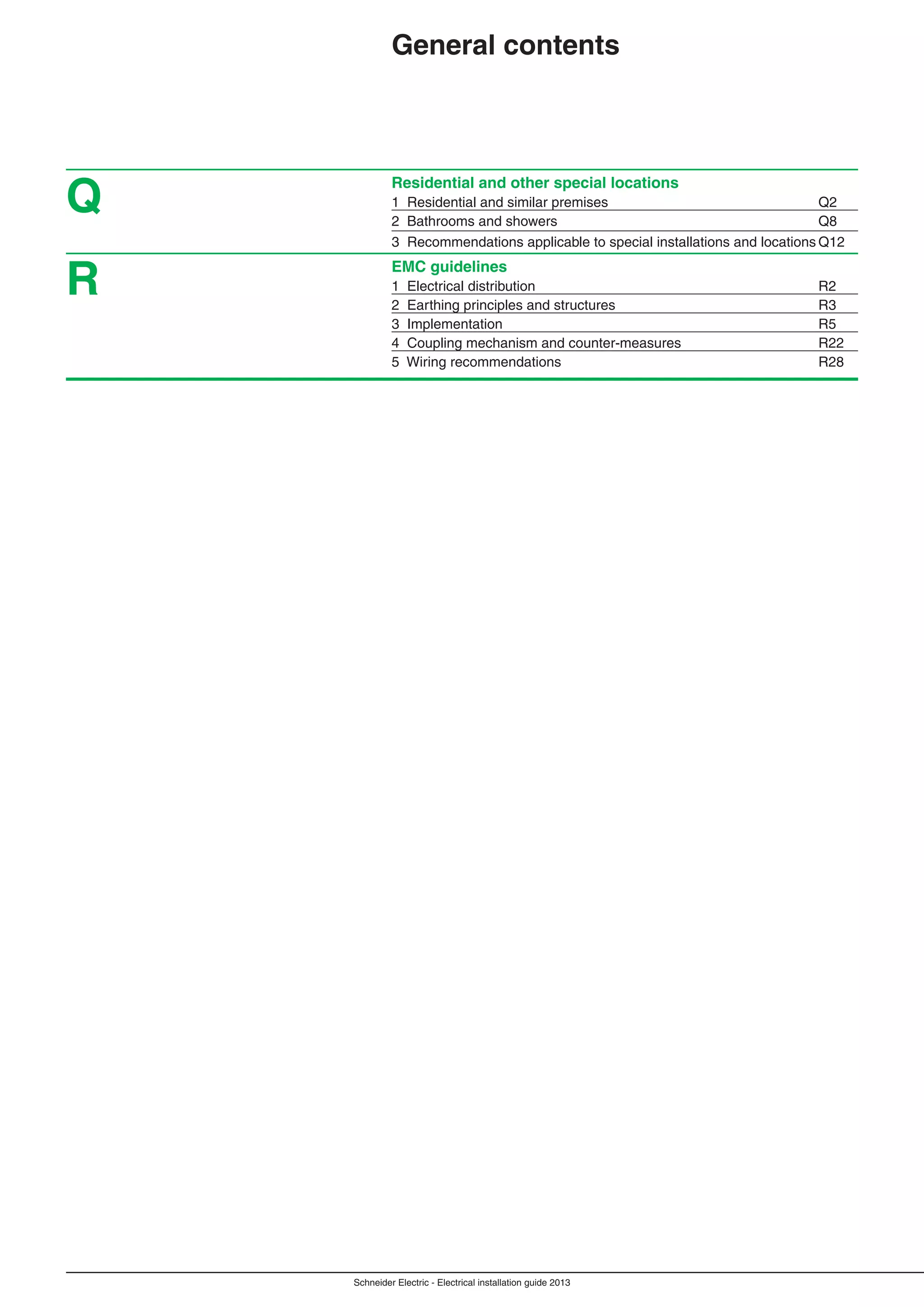
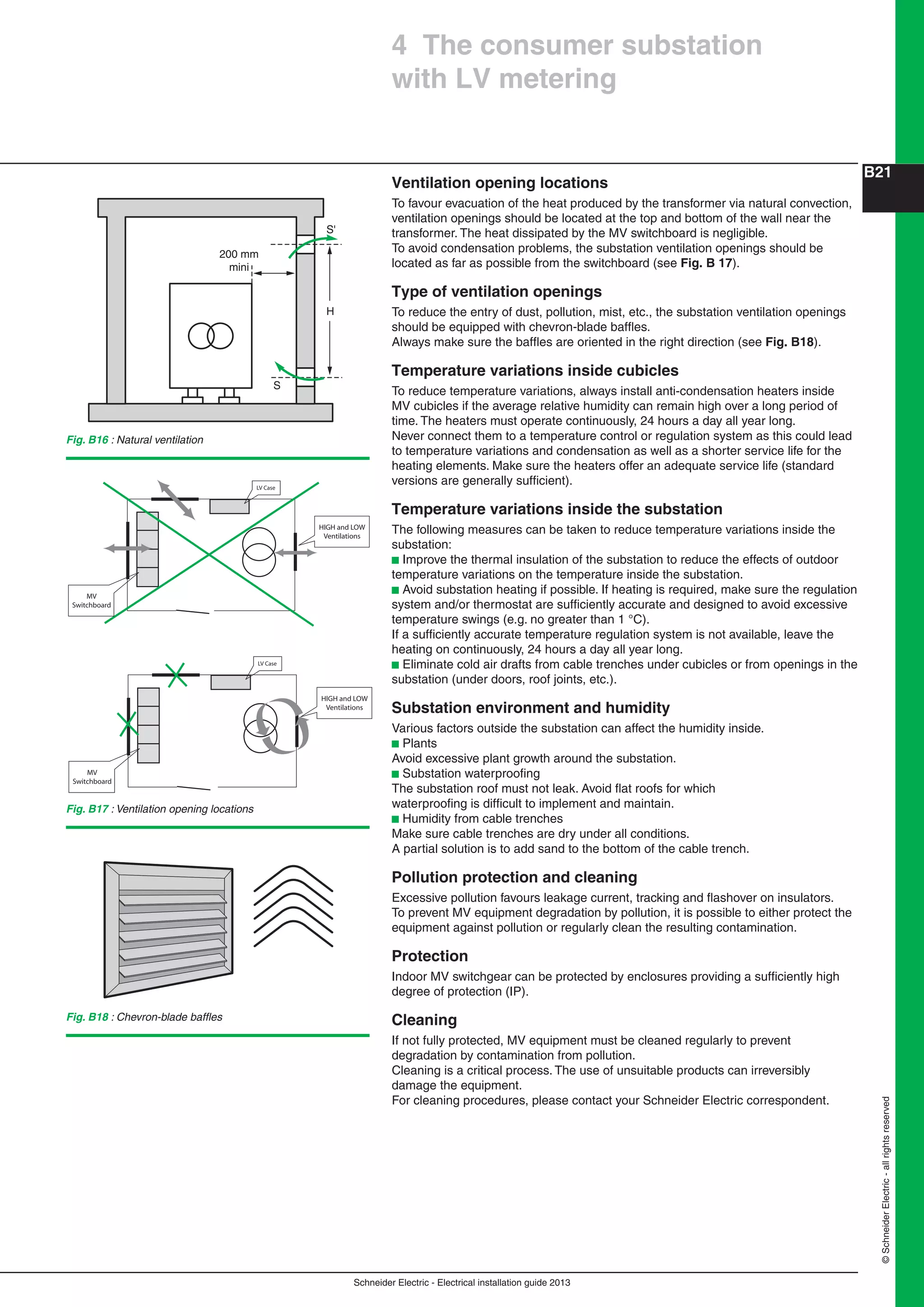
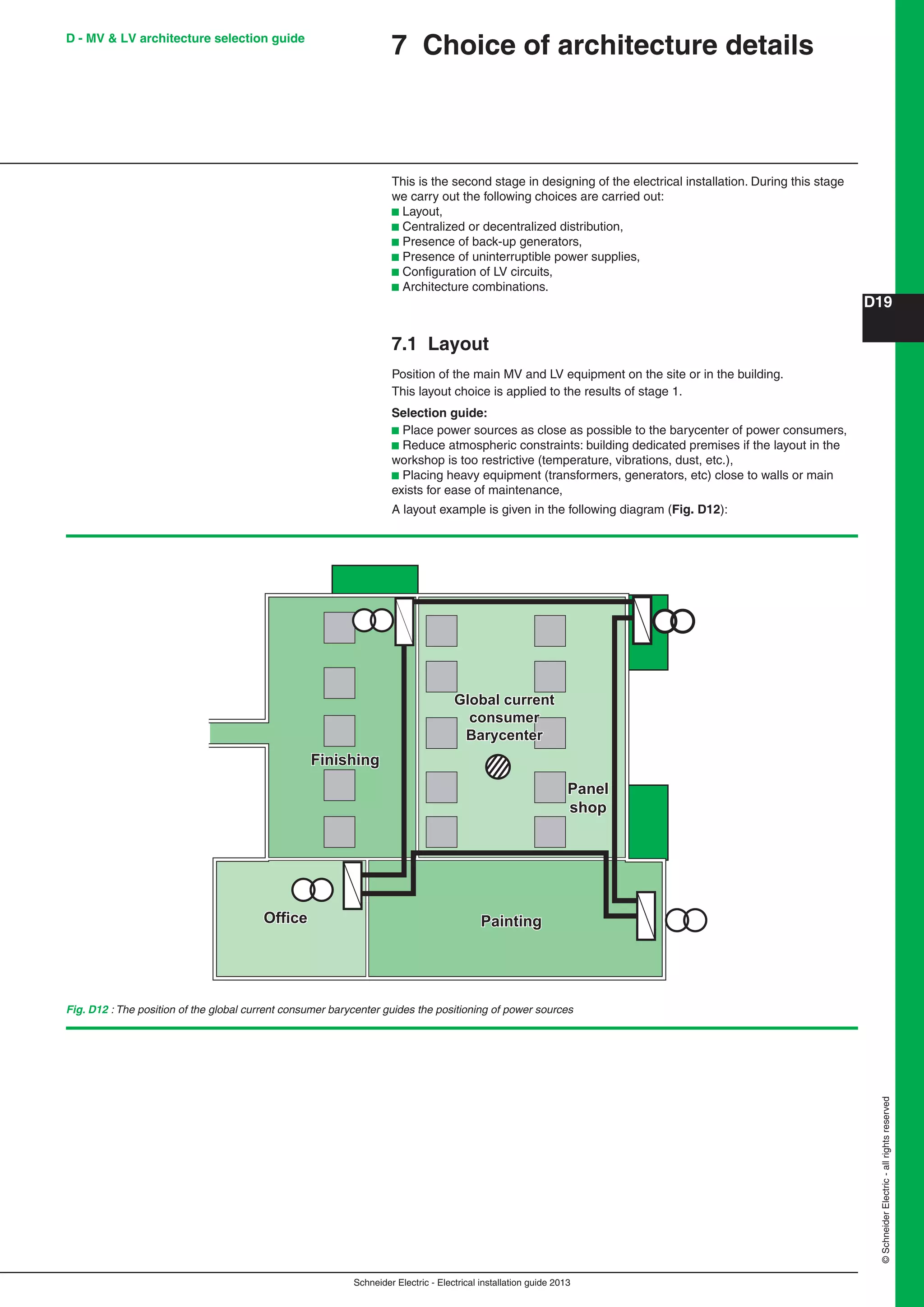
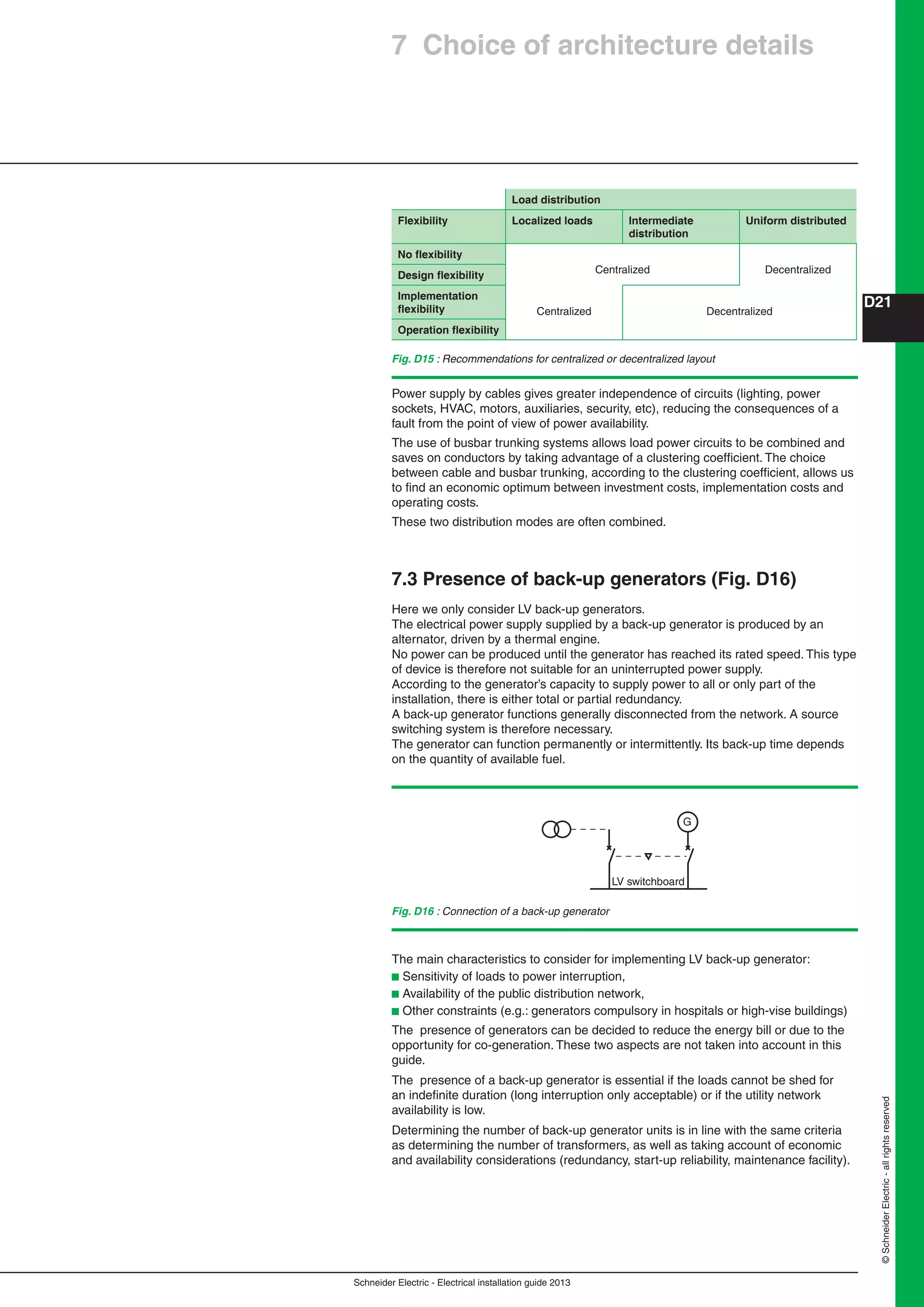
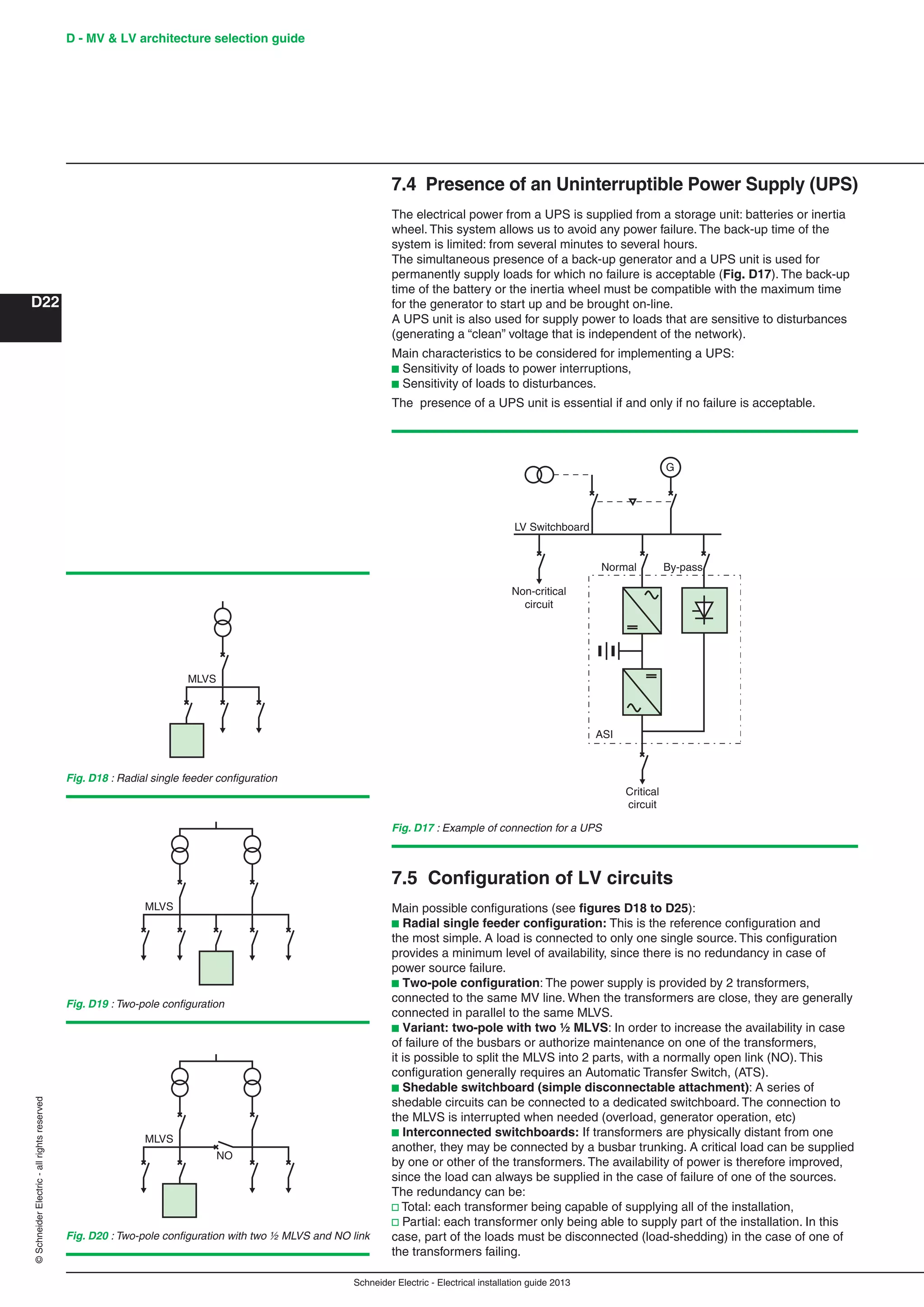
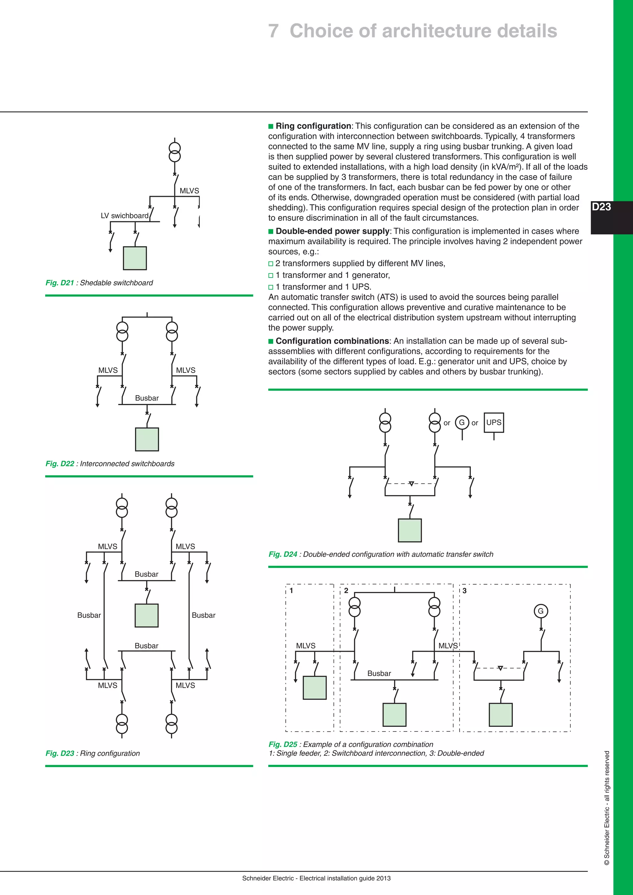
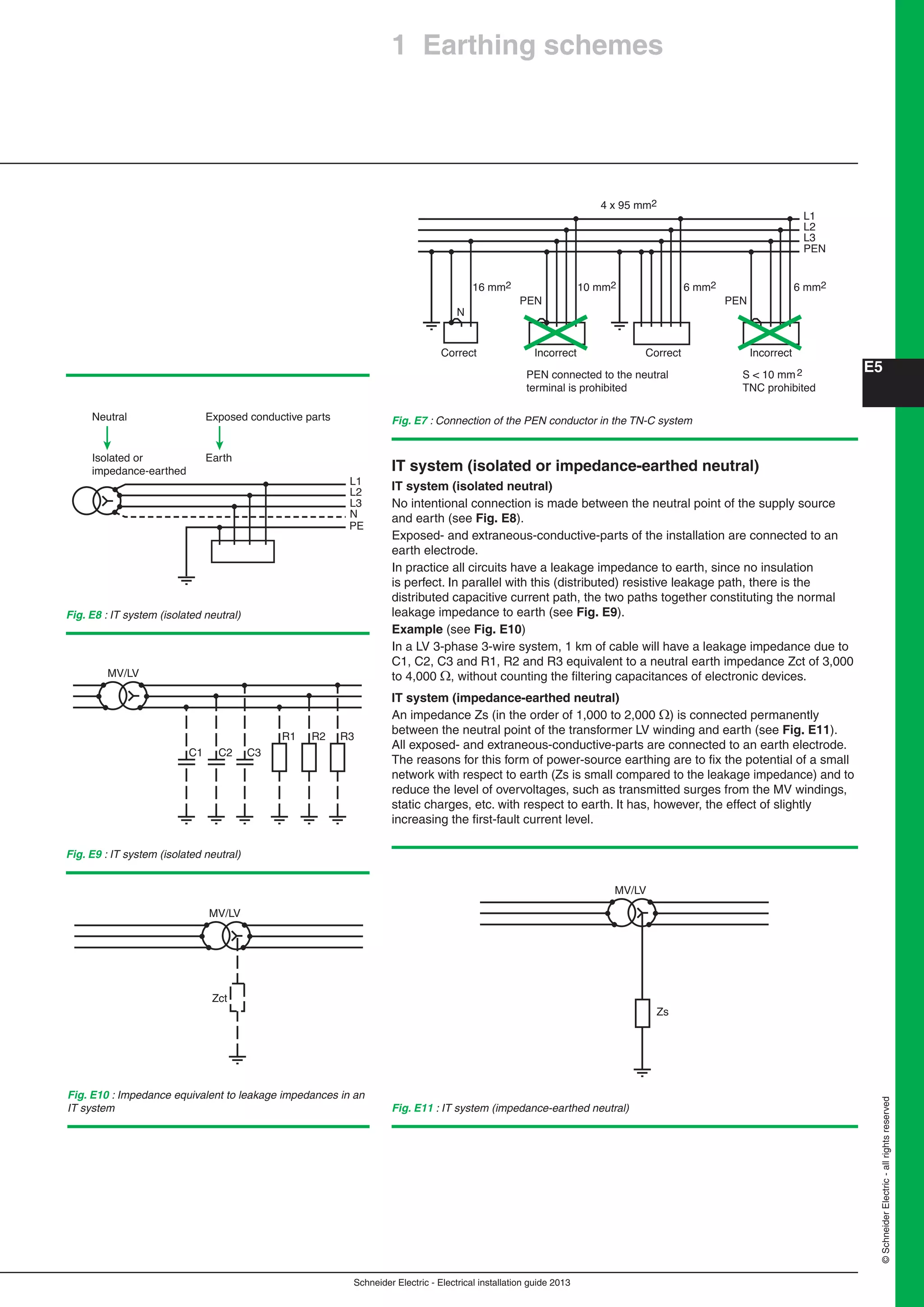
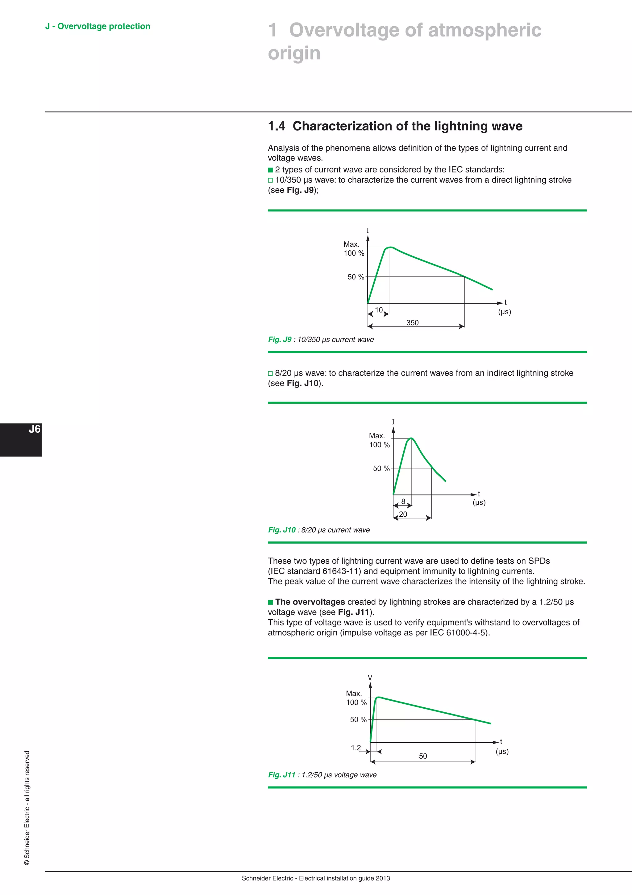
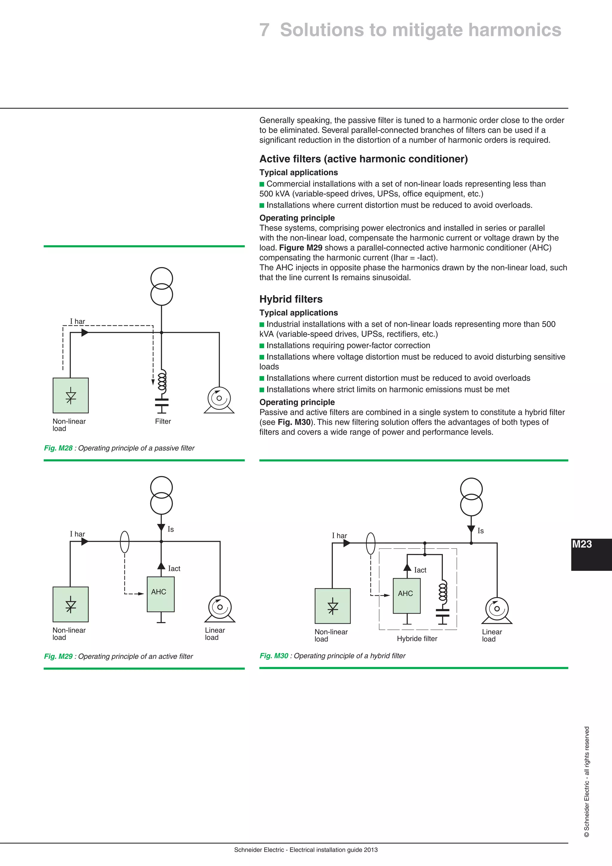
Ventilation
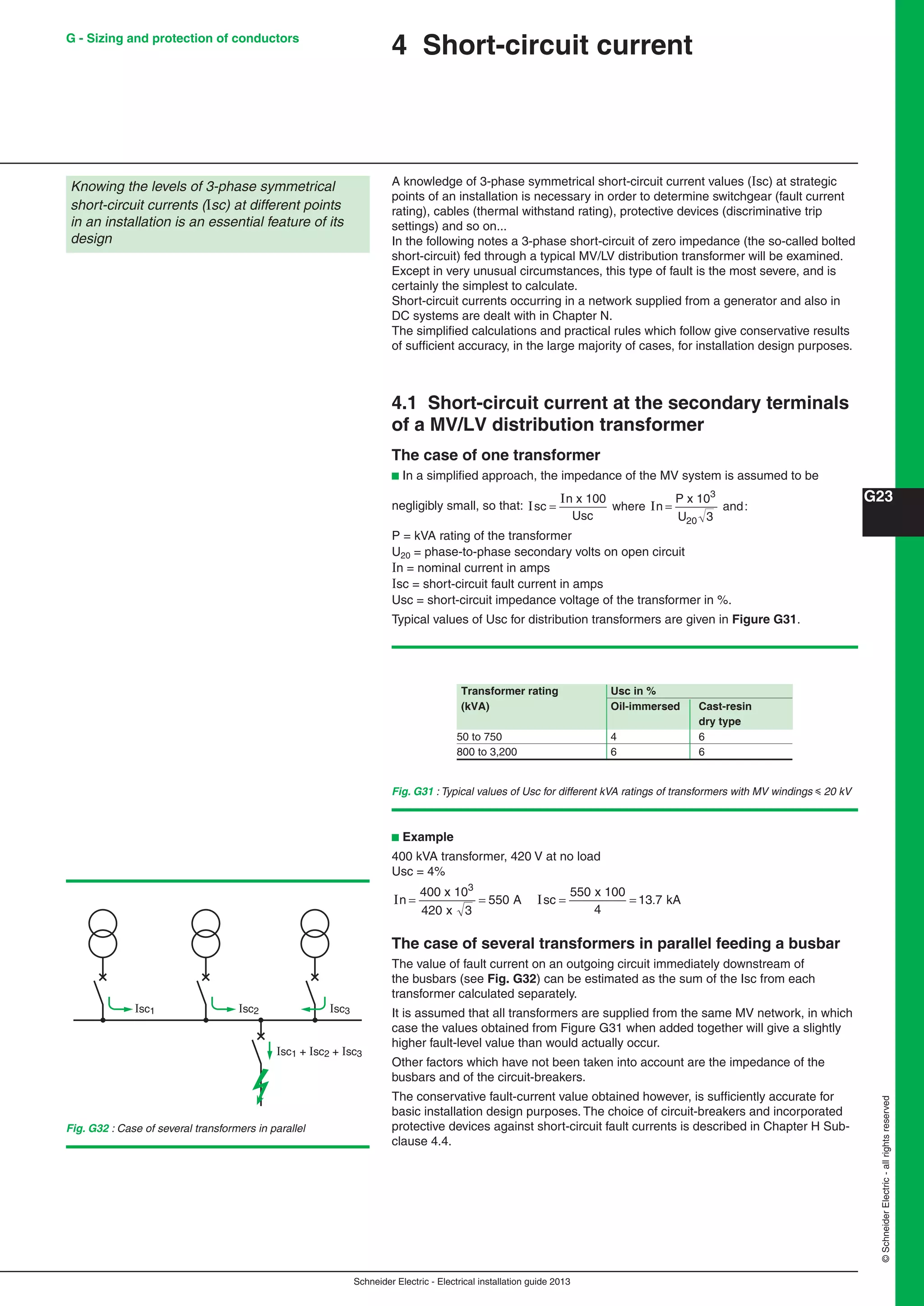
Substation ventilation is generally required to dissipate the heat produced by
transformers and to allow drying after particularly wet or humid periods.
However, a number of studies have shown that excessive ventilation can drastically
increase condensation.
Ventilation should therefore be kept to the minimum level required.
Furthermore, ventilation should never generate sudden temperature variations that
can cause the dew point to be reached.
For this reason:
Natural ventilation should be used whenever possible. If forced ventilation is
necessary, the fans should operate continuously to avoid temperature fluctuations.
Guidelines for sizing the air entry and exit openings of substations are presented
hereafter.
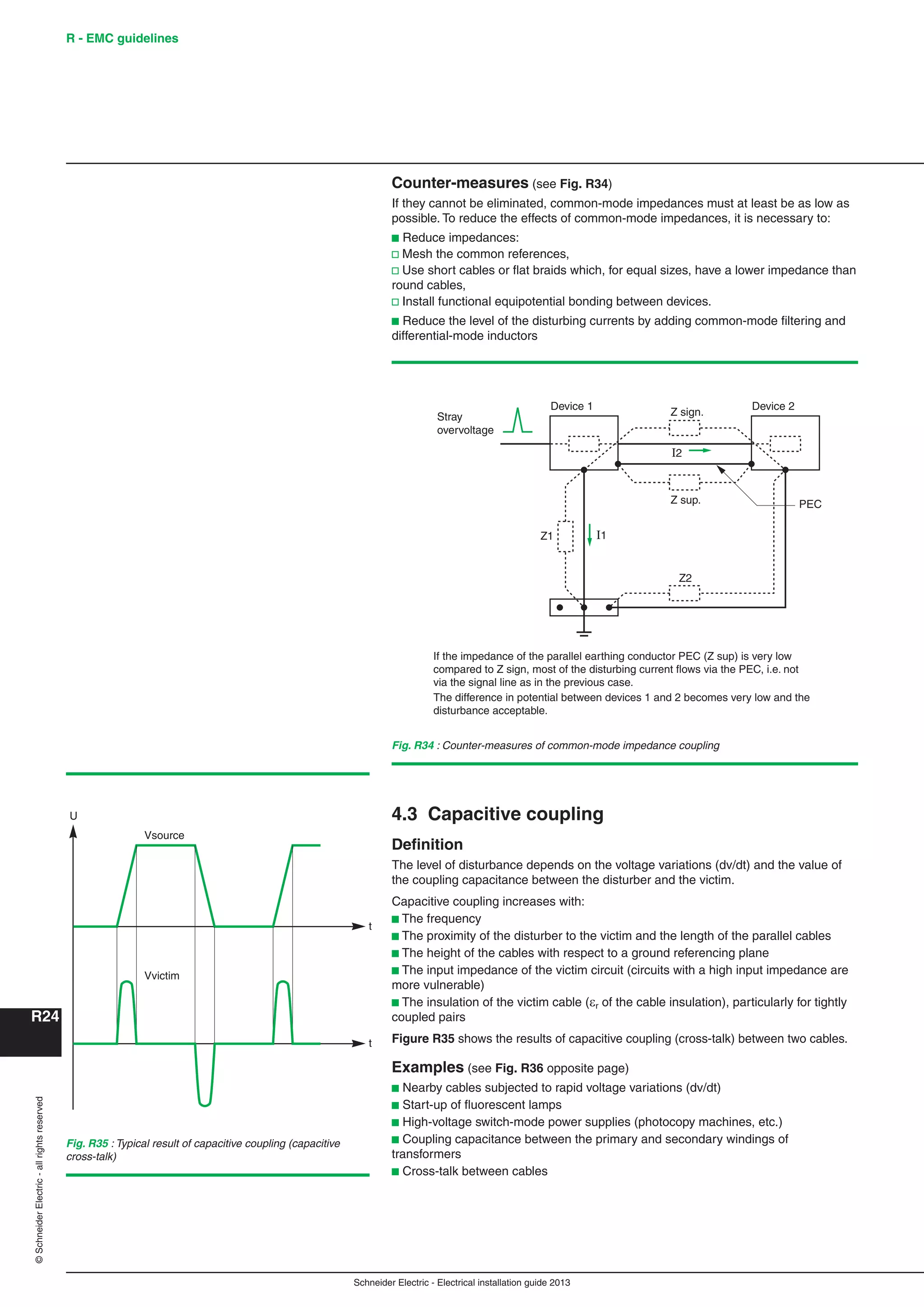
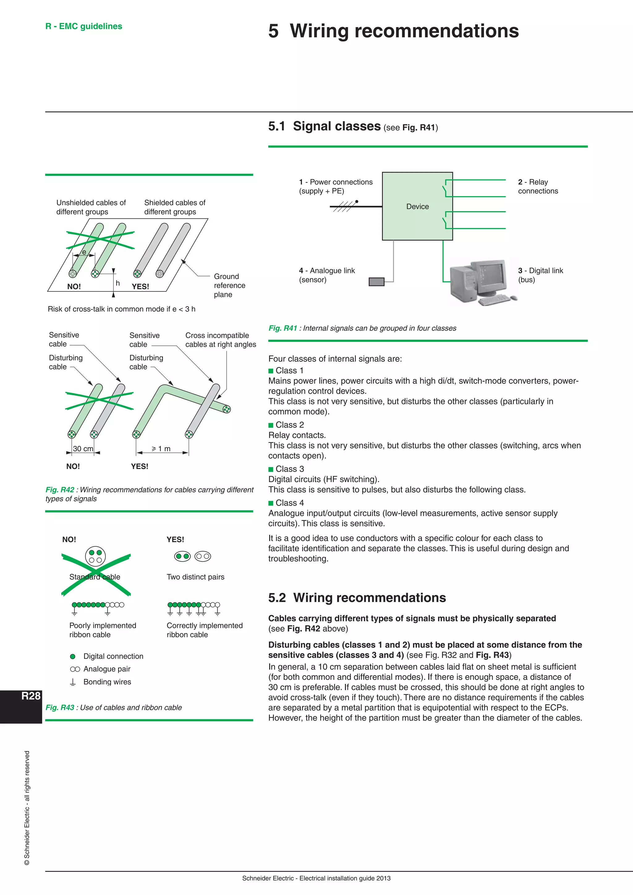
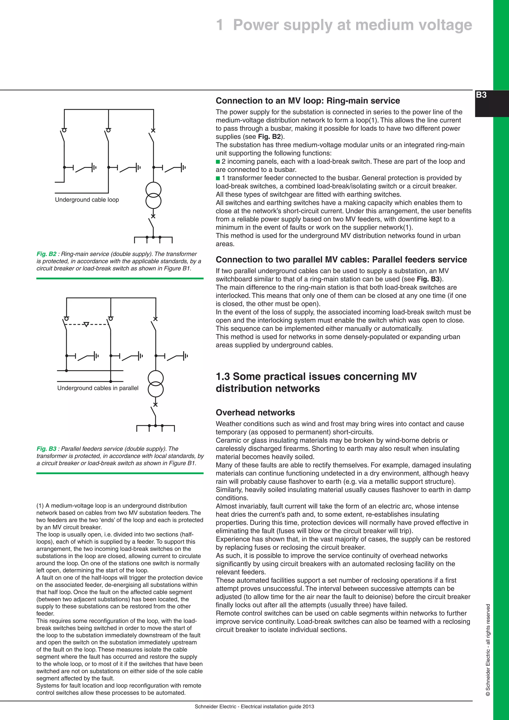
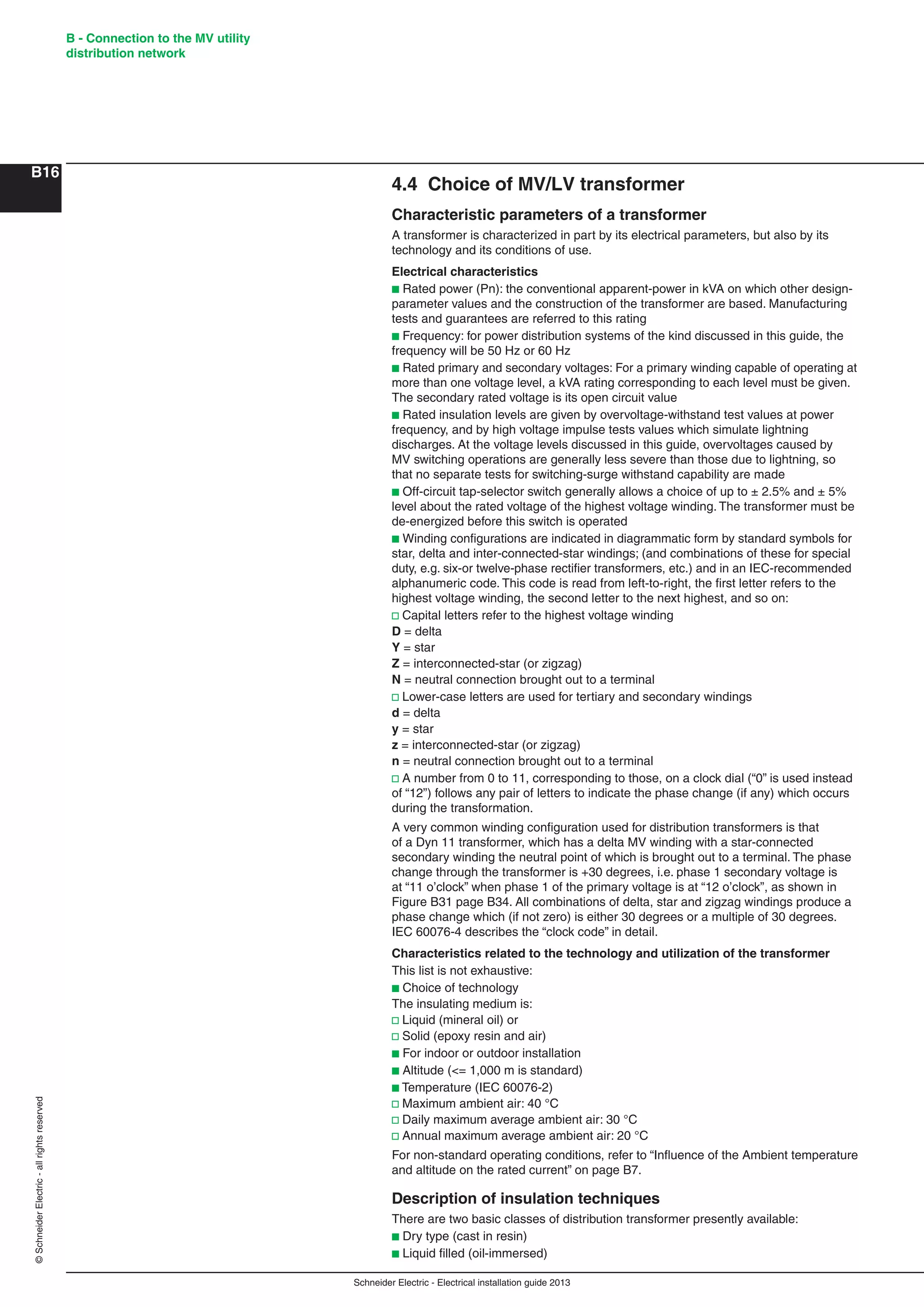
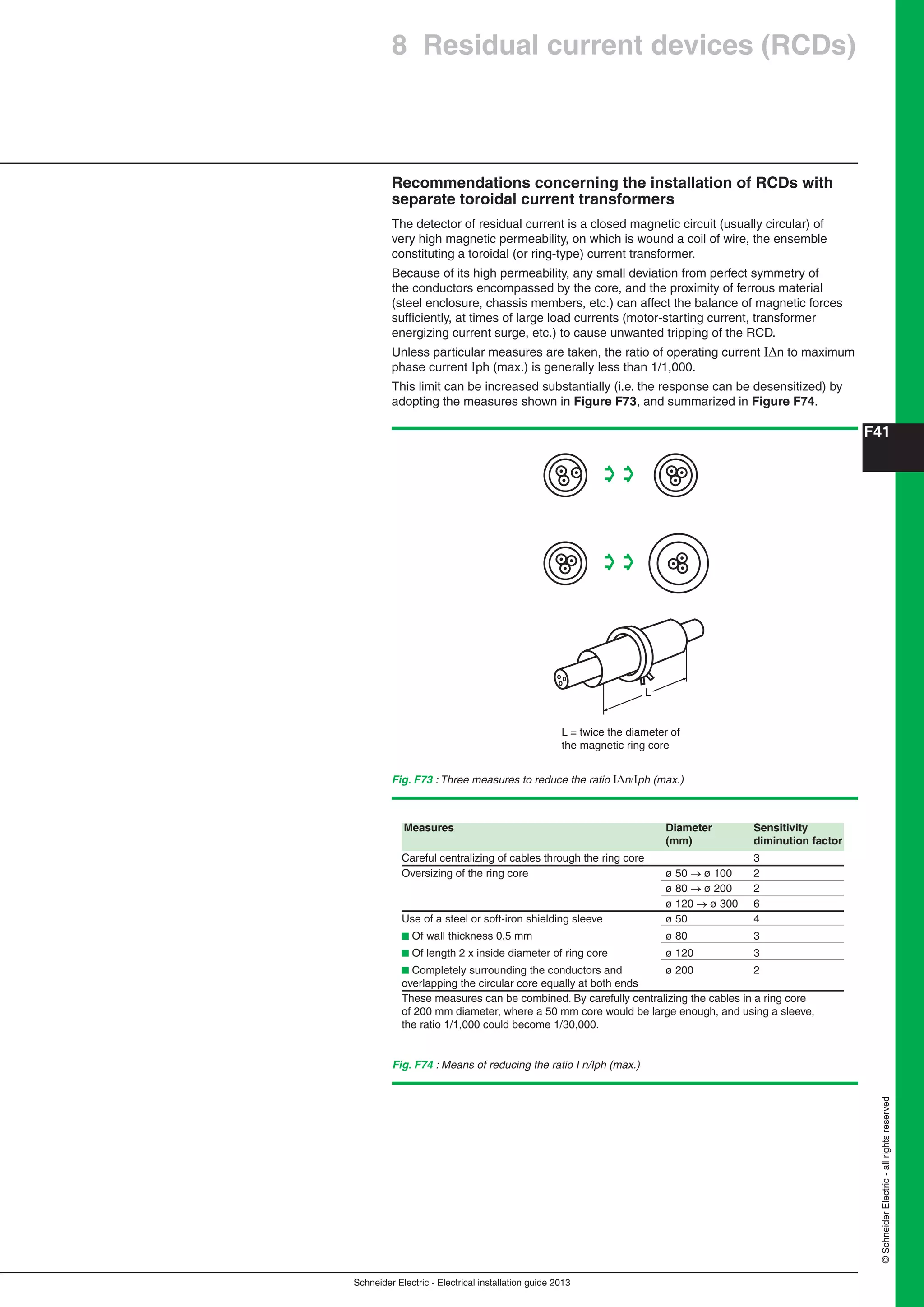
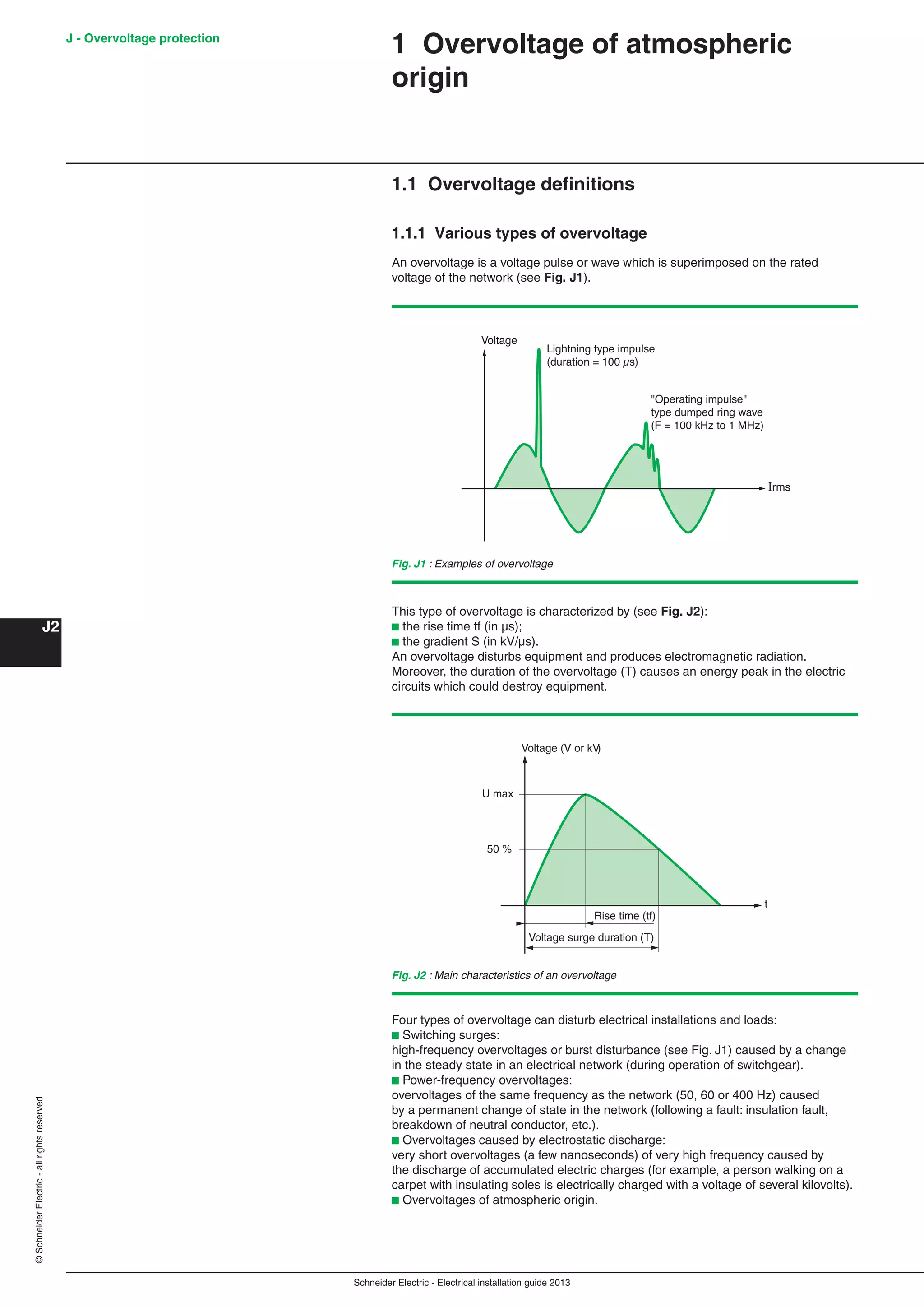
Calculation methods
A number of calculation methods are available to estimate the required size of
substation ventilation openings, either for the design of new substations or the
adaptation of existing substations for which condensation problems have occurred.
The basic method is based on transformer dissipation.
The required ventilation opening surface areas S and S’ can be estimated using the
following formulas:
S
1.8 x 10⁻⁴
P
H
and S' 1.10 x S
where:
S = Lower (air entry) ventilation opening area [m²] (grid surface deducted)
S’= Upper (air exit) ventilation opening area [m²] (grid surface deducted)
P = Total dissipated power [W]
P is the sum of the power dissipated by:
b The transformer (dissipation at no load and due to load)
b The LV switchgear
b The MV switchgear
H = Height between ventilation opening mid-points [m]
See Fig. B16
Note:
This formula is valid for a yearly average temperature of 20 °C and a maximum
altitude of 1,000 m.
It must be noted that these formulae are able to determine only one order of
magnitude of the sections S and S', which are qualified as thermal section, i.e. fully
open and just necessary to evacuate the thermal energy generated inside the MV/LV
substation.
The pratical sections are of course larger according ot the adopted technological
solution.
Indeed, the real air flow is strongly dependant:
b on the openings shape and solutions adopted to ensure the cubicle protection
index (IP): metal grid, stamped holes, chevron louvers,...
b on internal components size and their position compared to the openings:
transformer and/or retention oil box position and dimensions, flow channel between
the components, ...
b and on some physical and environmental parameters: outside ambient
temperature, altitude, magnitude of the resulting temperature rise.
The understanding and the optimization of the attached physical phenomena are
subject to precise flow studies, based on the fluid dynamics laws, and realized with
specific analytic software.
Example:
Transformer dissipation = 7,970 W
LV switchgear dissipation = 750 W
MV switchgear dissipation = 300 W
The height between ventilation opening mid-points is 1.5 m.
Calculation:
Dissipated Power P = 7,970 + 750 + 300 = 9,020 W
S
1.8 x 10⁻⁴
P
1.5
1.32 m2
and S' 1.1 x 1.32 1.46 m2](https://image.slidesharecdn.com/manualinstalacioneselectricas-150309124103-conversion-gate01/75/Manual-instalaciones-electricas-52-2048.jpg)
![Schneider Electric - Electrical installation guide 2013
B29
©SchneiderElectric-allrightsreserved
Materials for operation and safety
According to local safety rules, generally, the substation is provided with:
b Materials for assuring safe exploitation of the equipment including:
v Insulating stool and/or an insulating mat (rubber or synthetic)
v A pair of insulated gloves stored in an envelope provided for the purpose
v A voltage-detecting device for use on the MV equipment
v Earthing attachments (according to type of switchgear)
b Fire-extinguishing devices of the powder or CO2 type
b Warning signs, notices and safety alarms:
v On the external face of all access doors, a DANGER warning plaque and
prohibition of entry notice, together with instructions for first-aid care for victims of
electrical accidents.
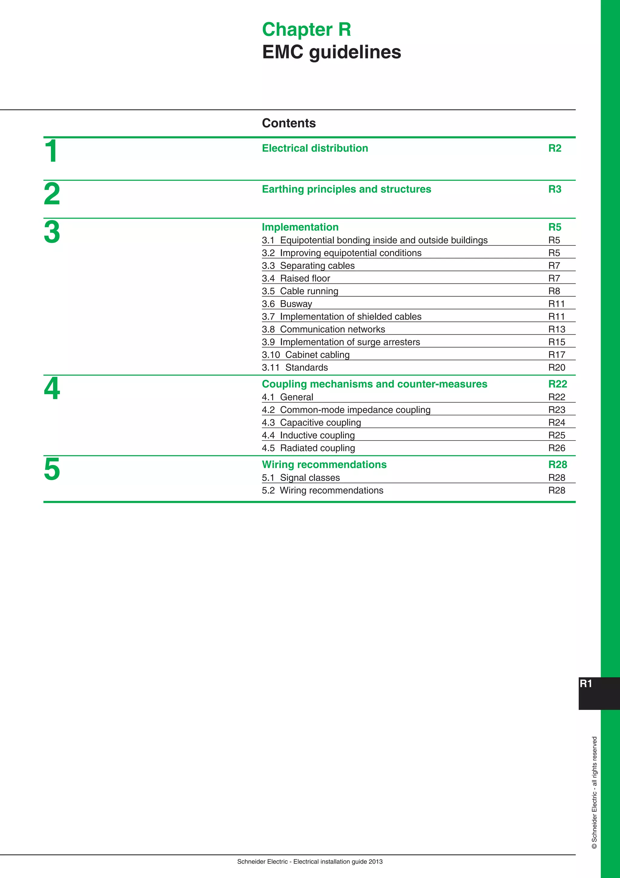
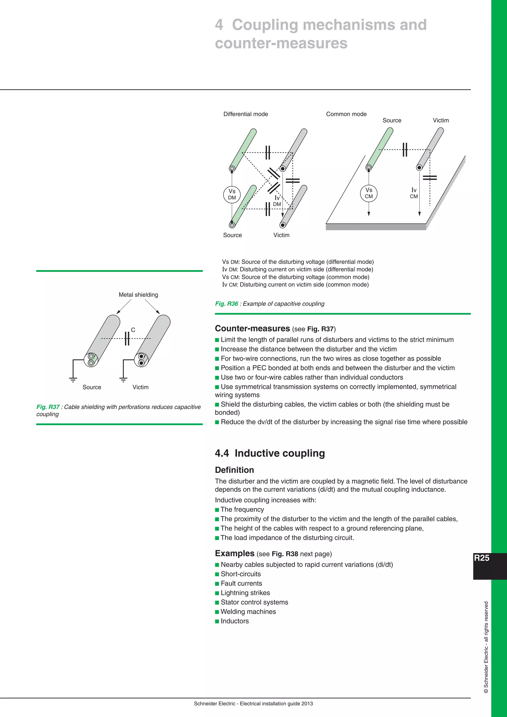
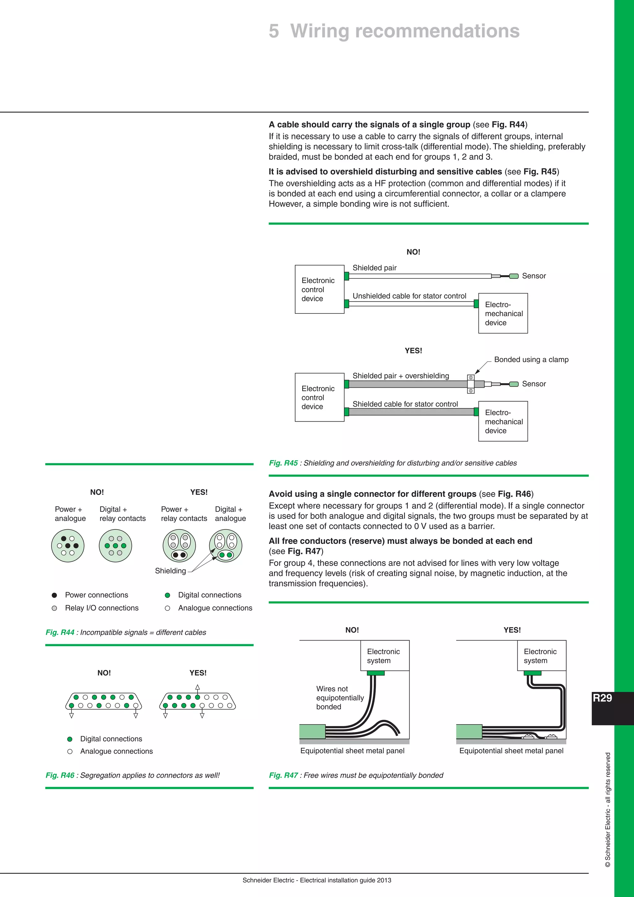
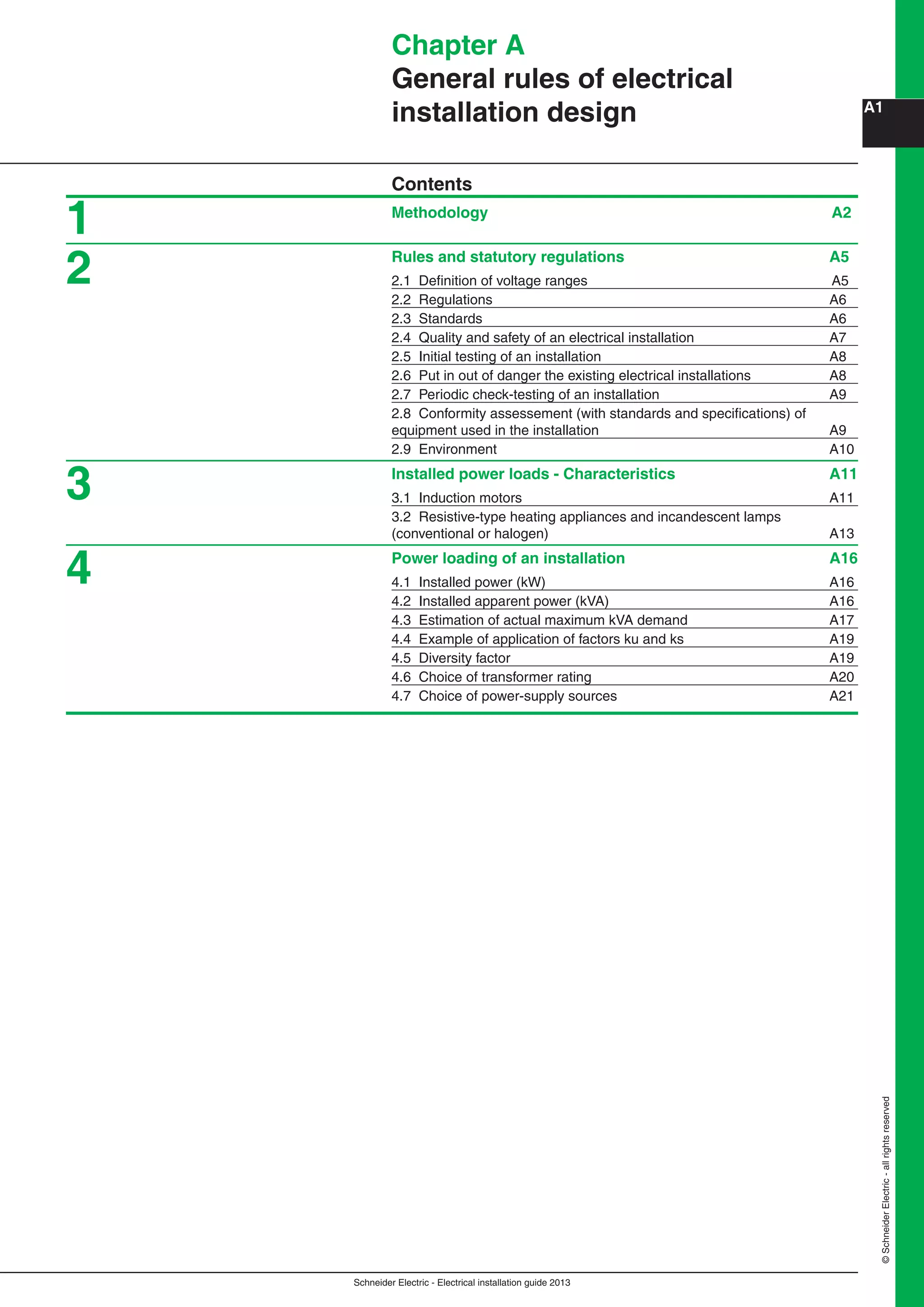
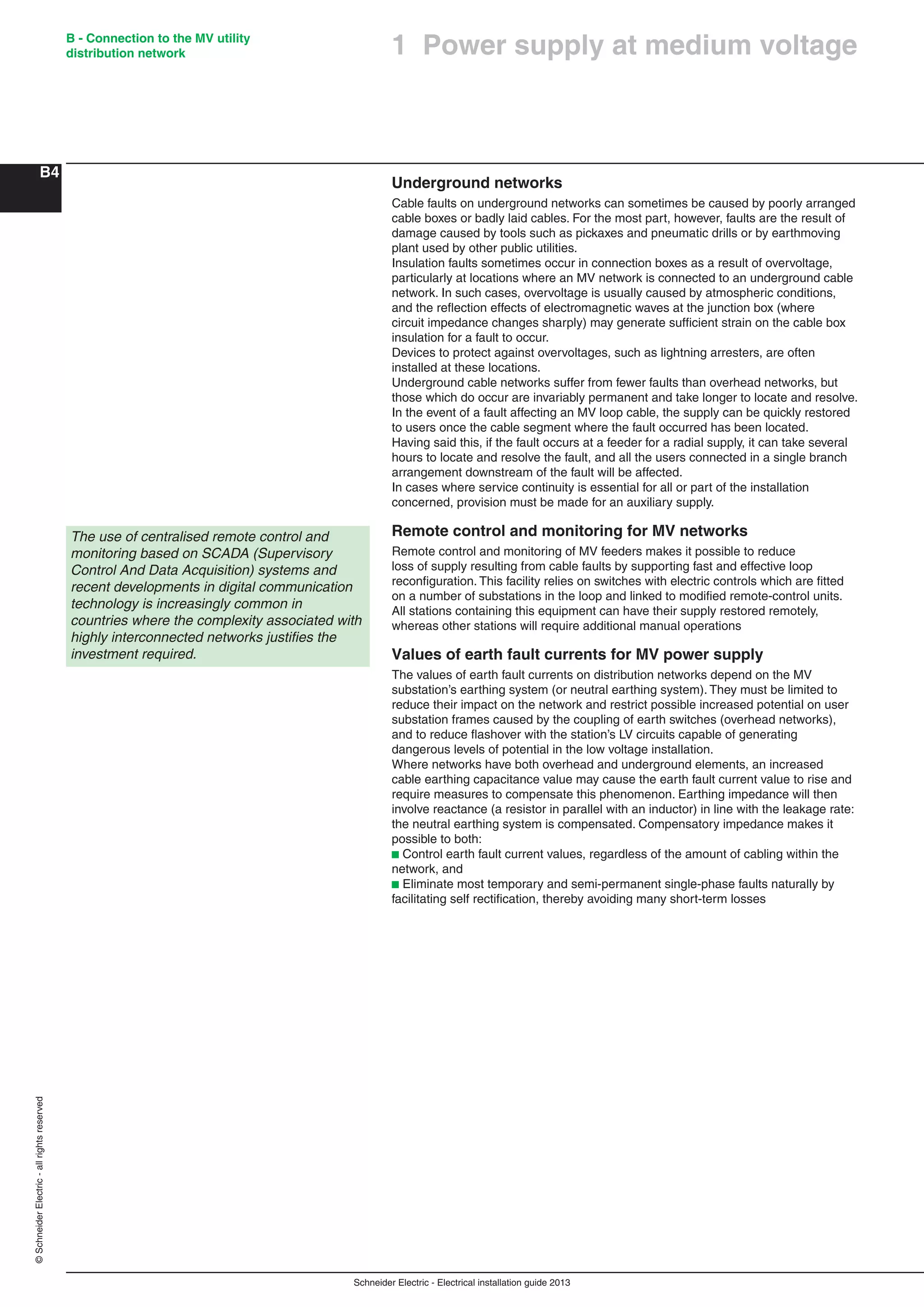
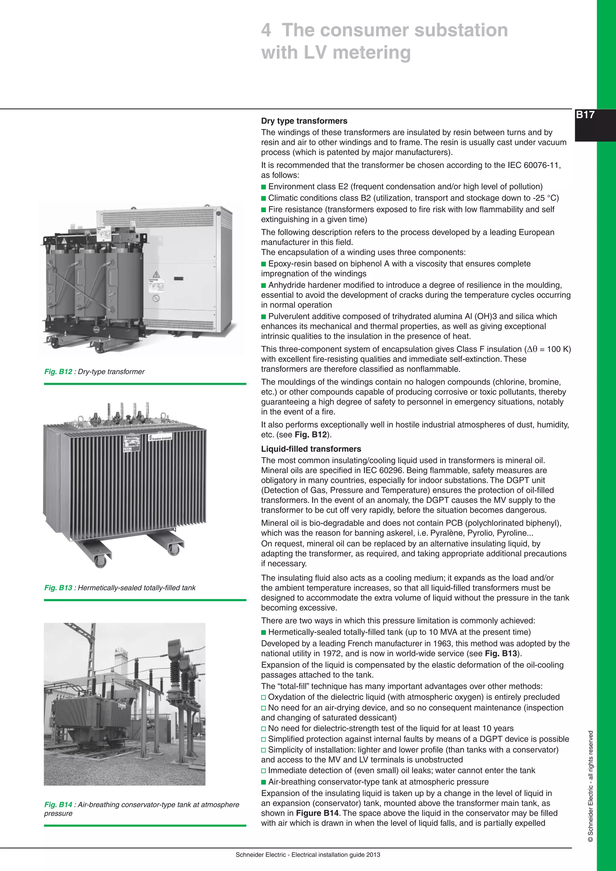
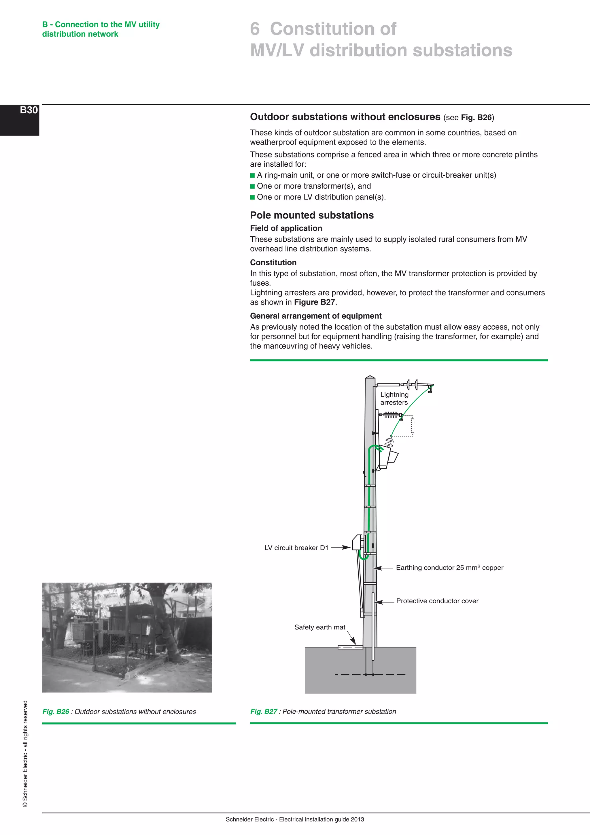
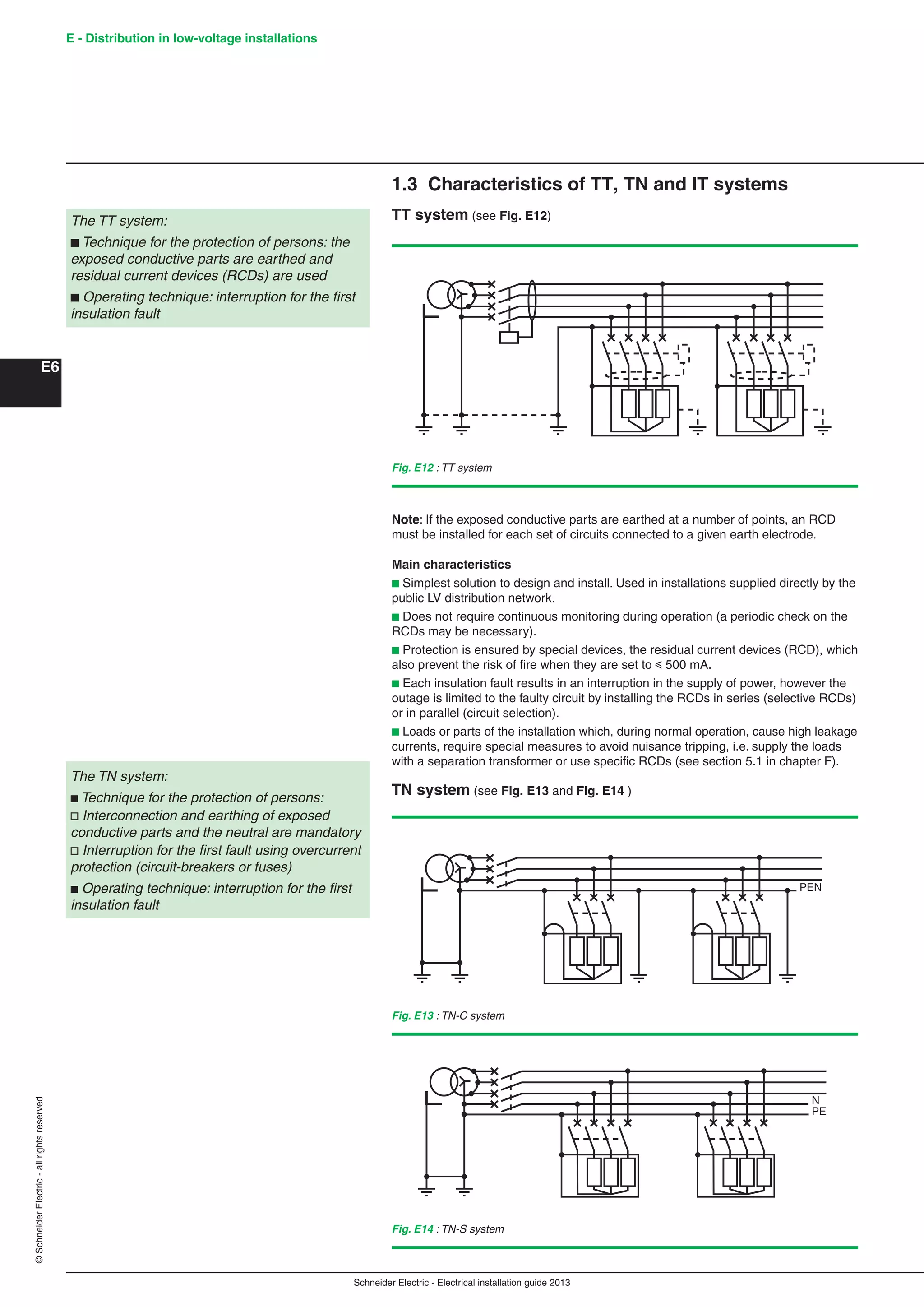
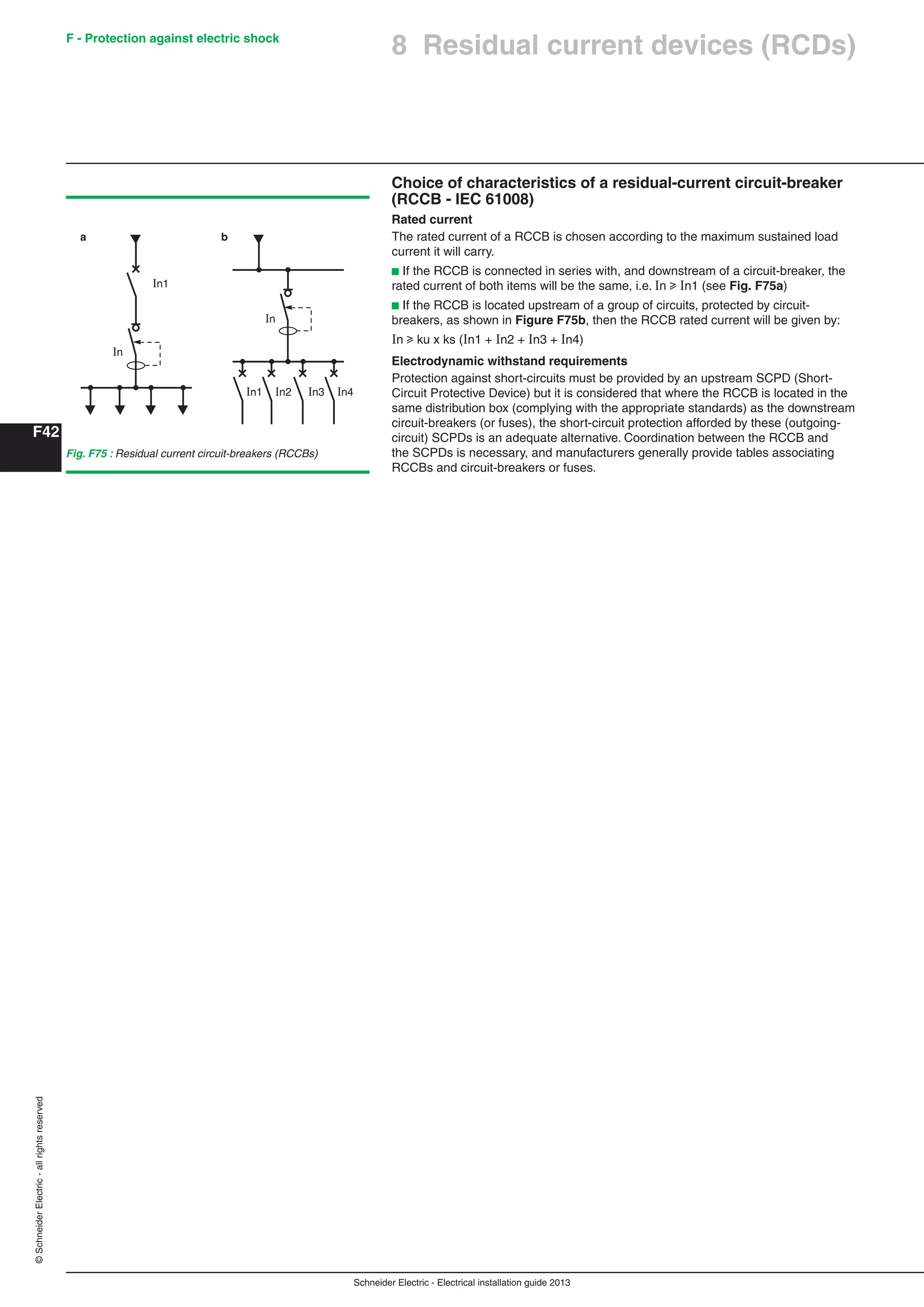
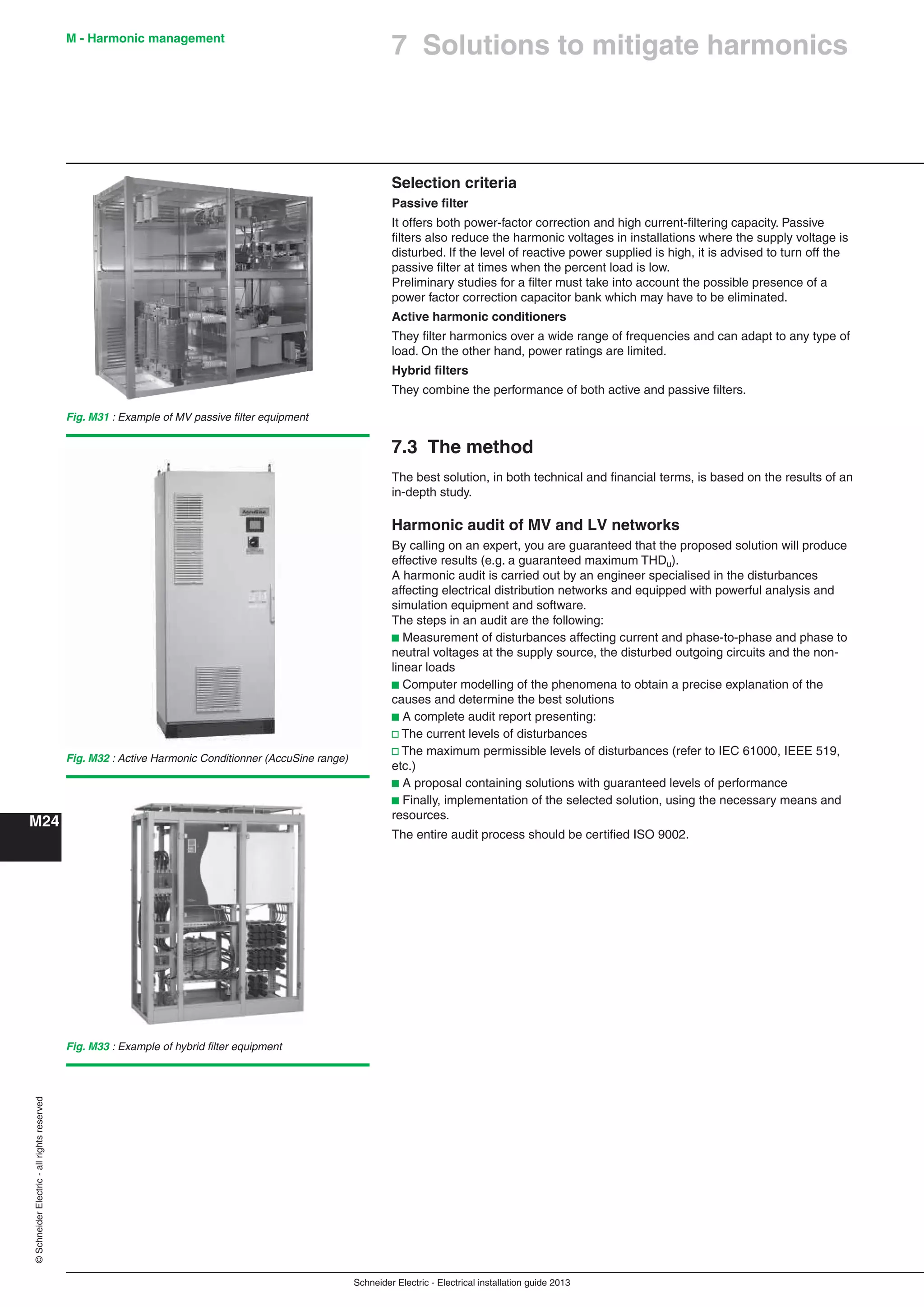
6.3 Outdoor substations
Outdoor substation with prefabricated enclosures
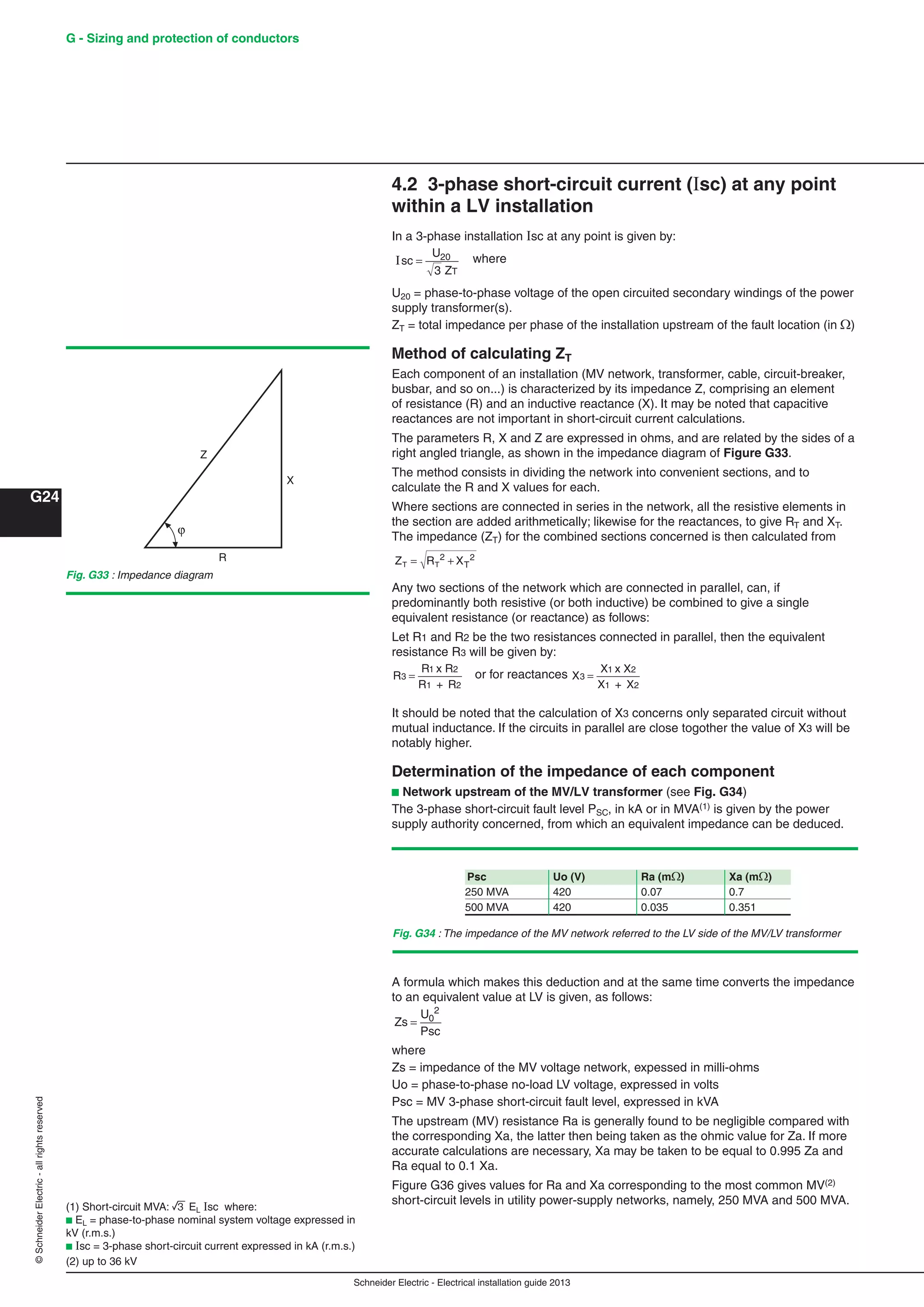
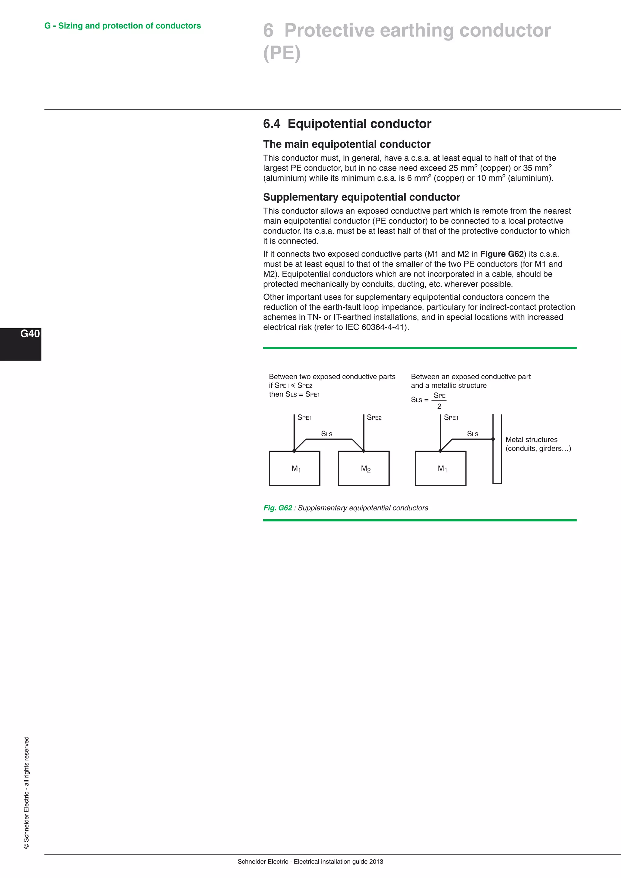
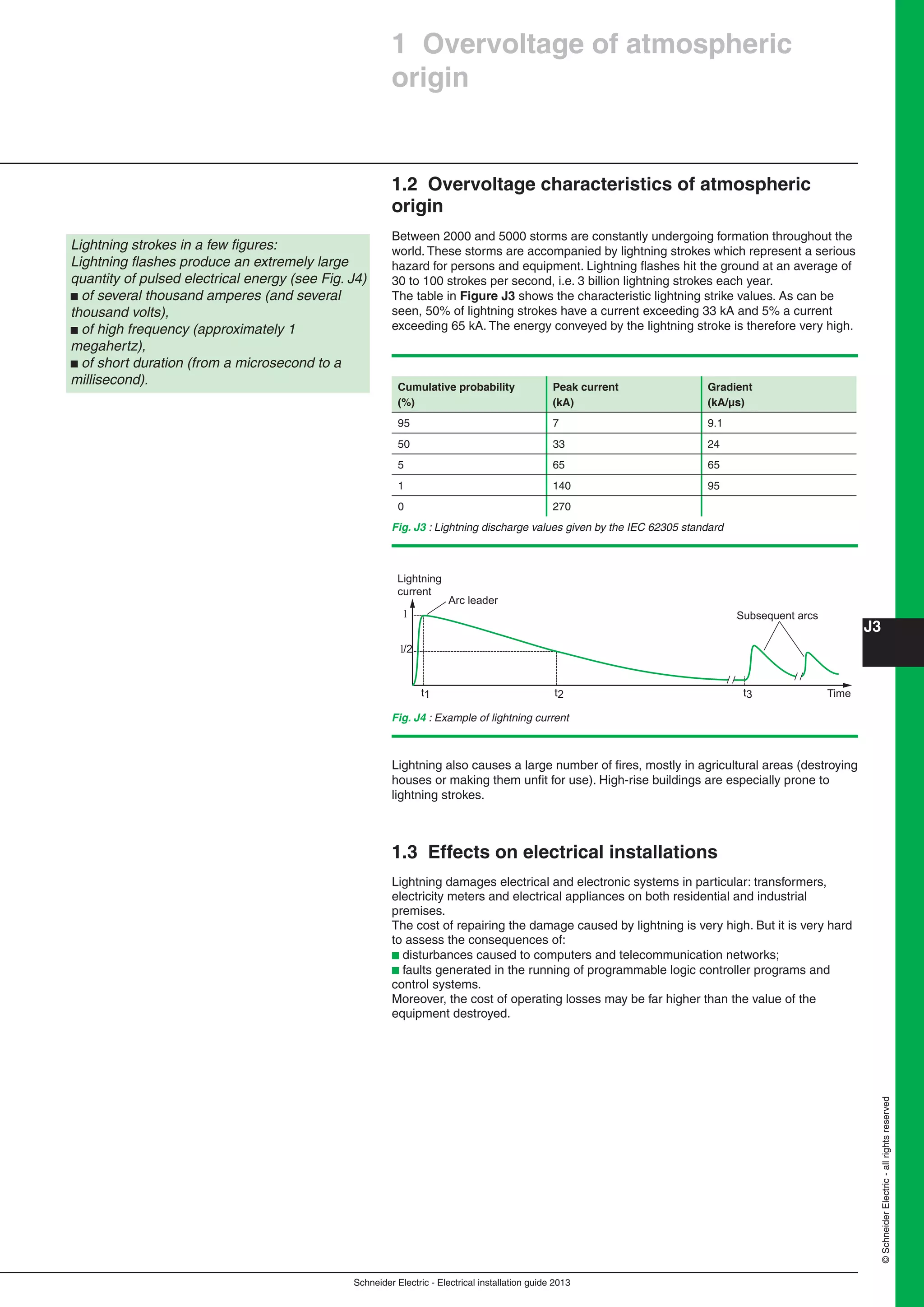
A prefabricated MV/LV substation complying with IEC 62271-202 standard includes :
b equipment in accordance with IEC standards
b a type tested enclosure, which means during its design, it has undergone a battery
of tests (see Fig. B24):
v Degree of protection
v Functional tests
v Temperature class
v Non-flammable materials
v Mechanical resistance of the enclosure
v Sound level
v Insulation level
v Internal arc withstand
v Earthing circuit test
v Oil retention,…
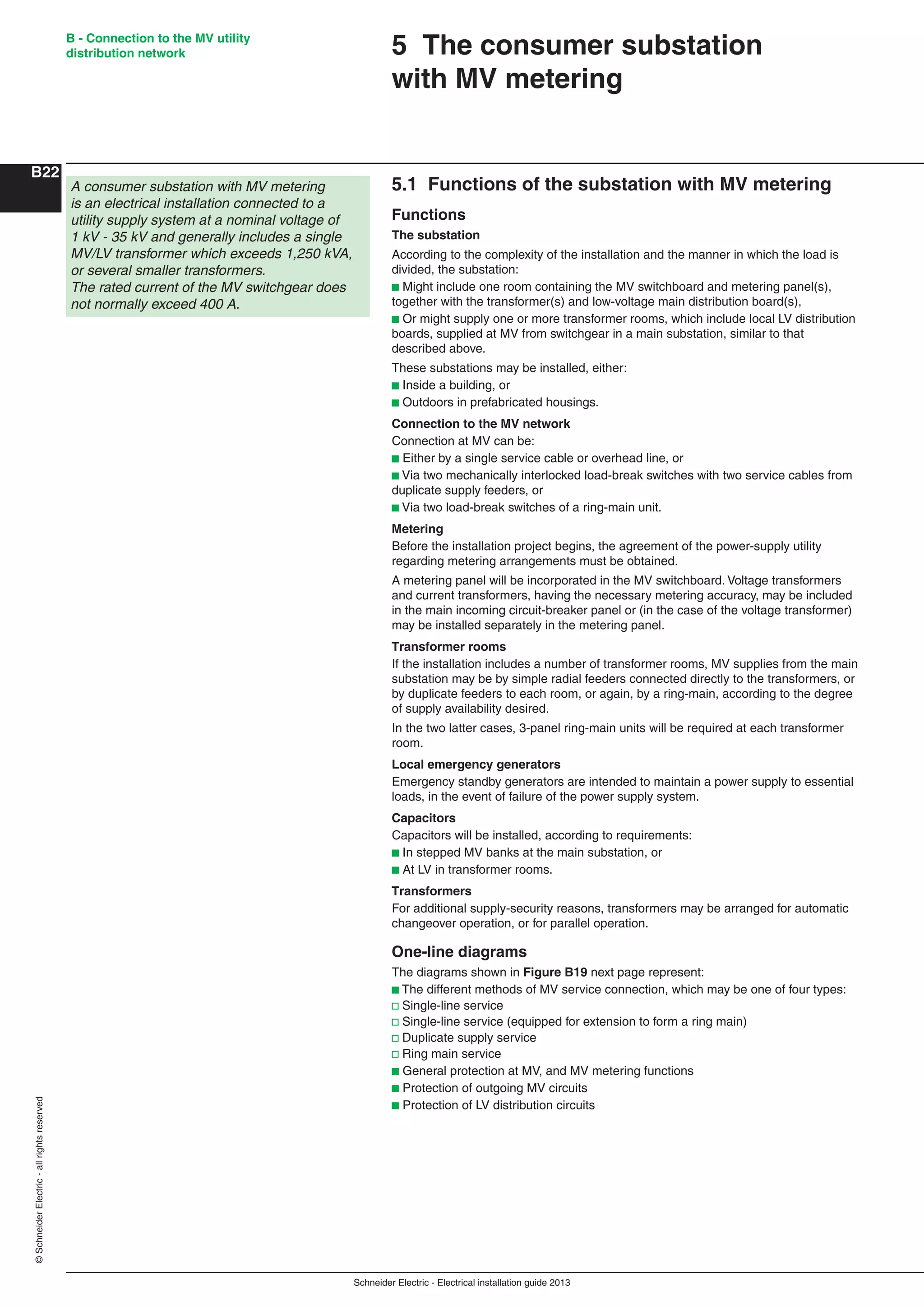
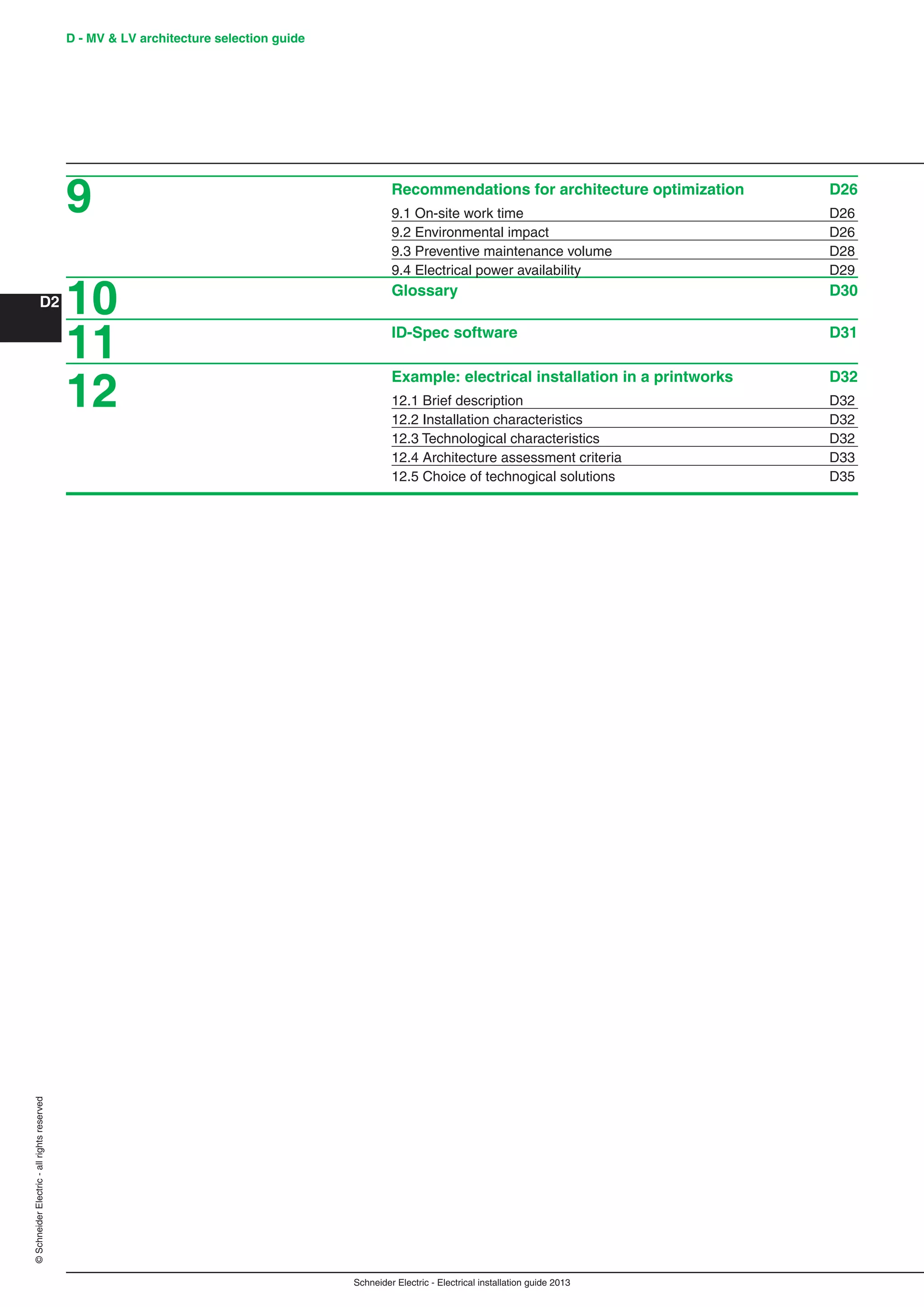
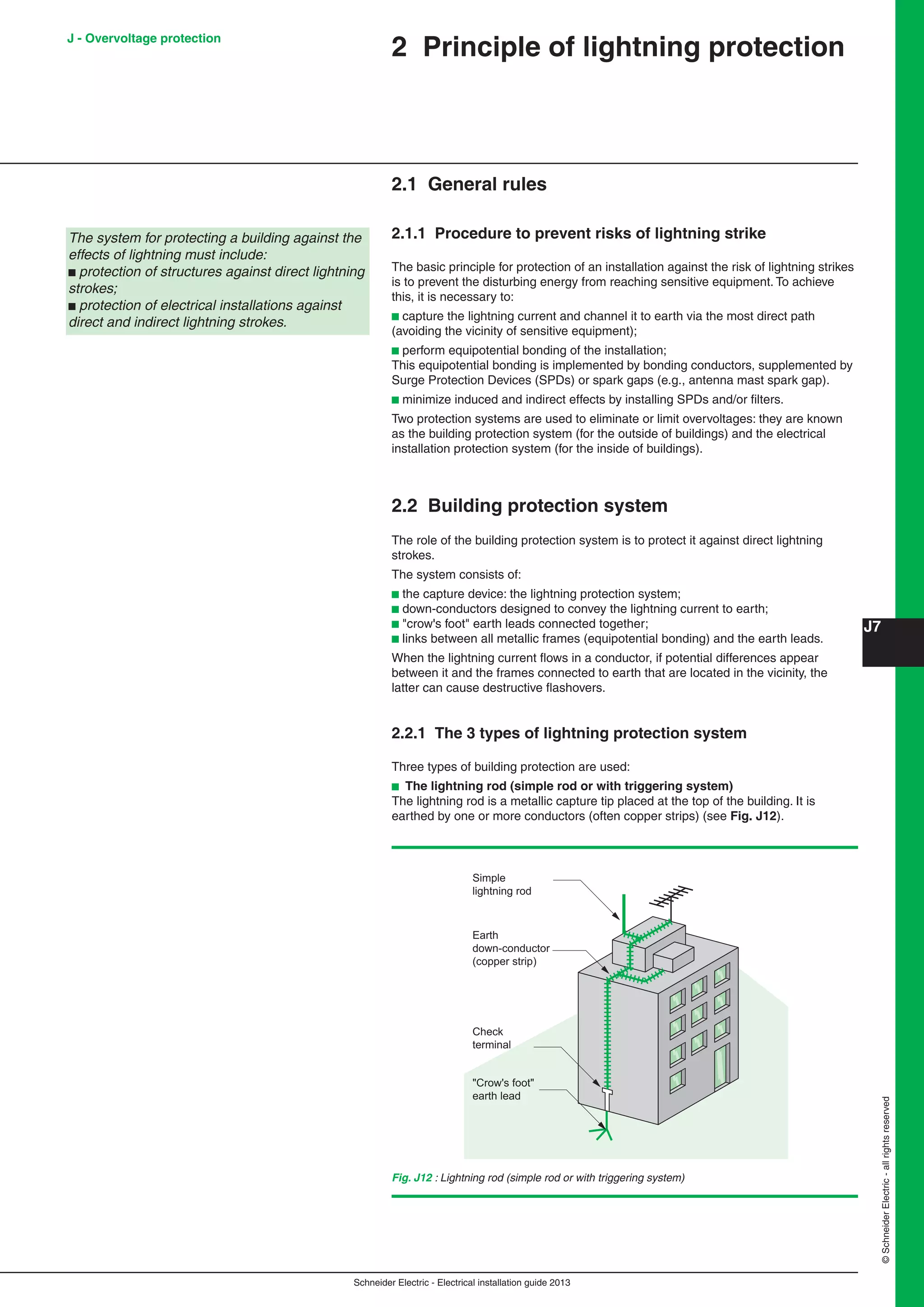
Fig. B24 : Type tested substation according to IEC 62271-202 standard
Fig. B25 : The four designs according to IEC 62271-202
standard and two pictures [a] walk-in type MV/LV substation;
[b] half buried type MV/LV substation
6 Constitution of
MV/LV distribution substations
Main benefits are :
b Safety:
v For public and operators thanks to a high reproducible quality level
b Cost effective:
v Manufactured, equipped and tested in the factory
b Delivery time
v Delivered ready to be connected.
IEC 62271-202 standard includes four main designs (see Fig. B25)
b Walk-in type substation :
v Operation protected from bad weather conditions
b Non walk-in substation
v Ground space savings, and outdoors operations
b Half buried substation
v Limited visual impact
b Underground substation
v Blends completely into the environment.
Use of equipment conform
to IEC standards:
b Degree of protection
b Electromagnetic
compatibility
b Functional tests
b Temperature class
b Non-flammable
materials
Mechanical resistance
of the enclosure:
b Sound level
b Insulation level
b Internal arcing
withstandLV
Earthing circuit test Oil retention
MV
Walk-in Non walk-in Half buried
Underground
a - b -](https://image.slidesharecdn.com/manualinstalacioneselectricas-150309124103-conversion-gate01/75/Manual-instalaciones-electricas-61-2048.jpg)


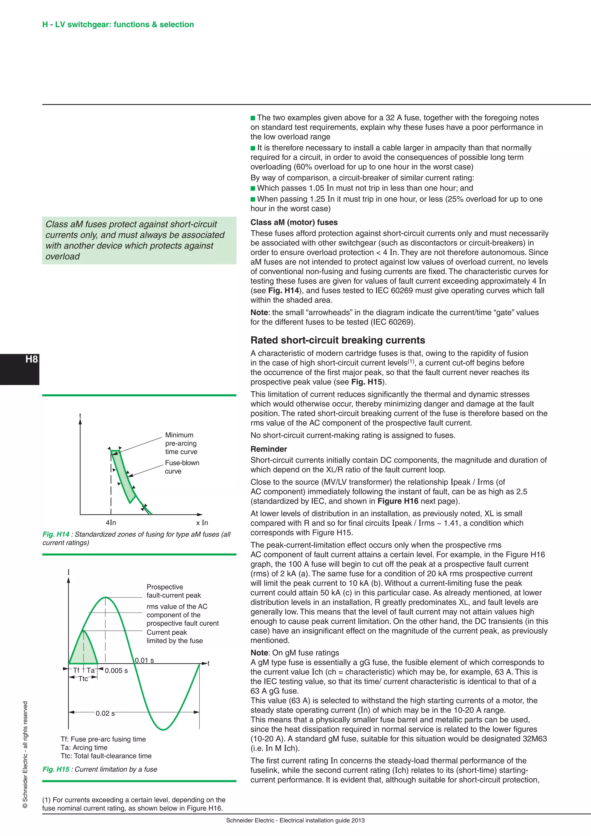
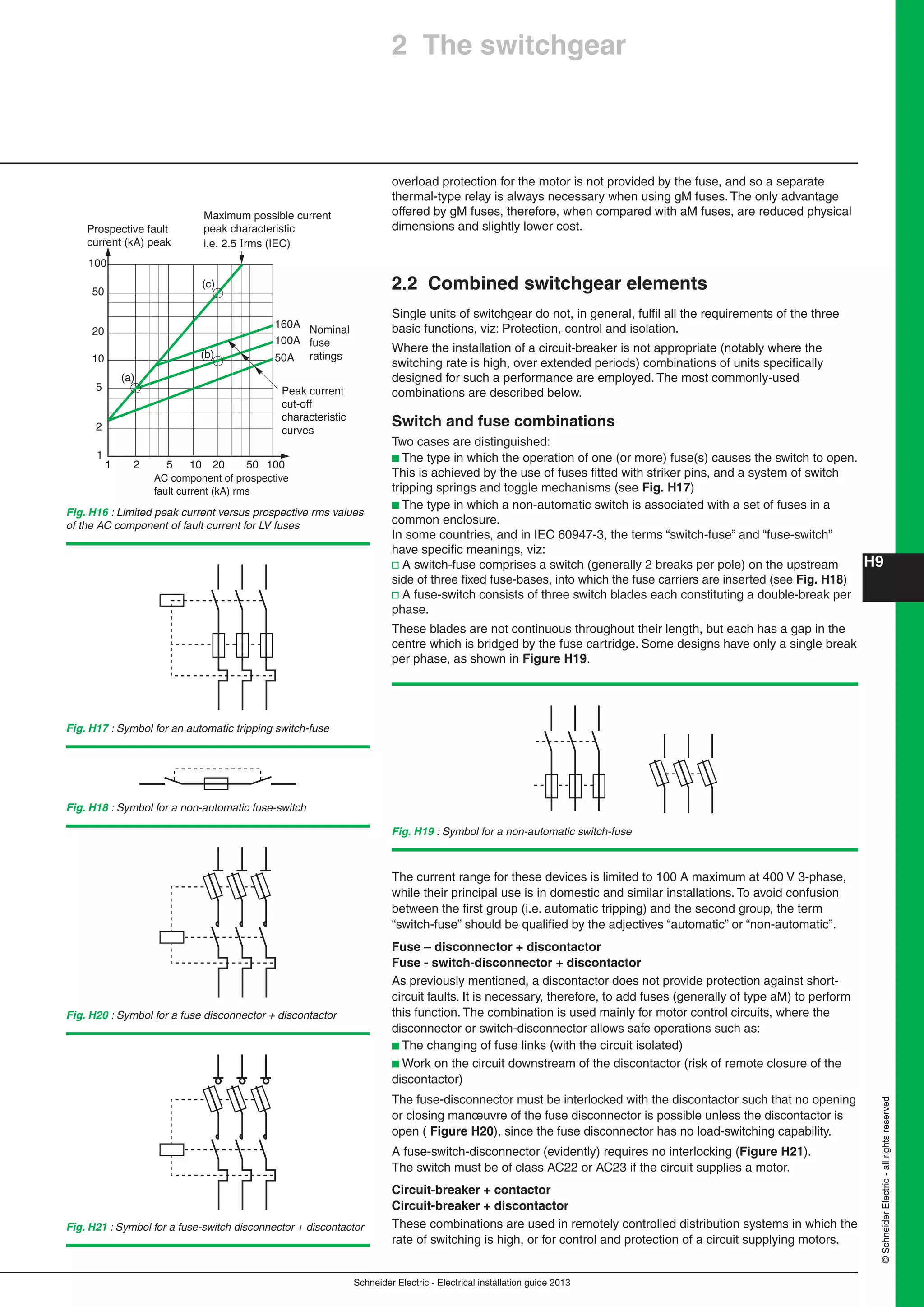
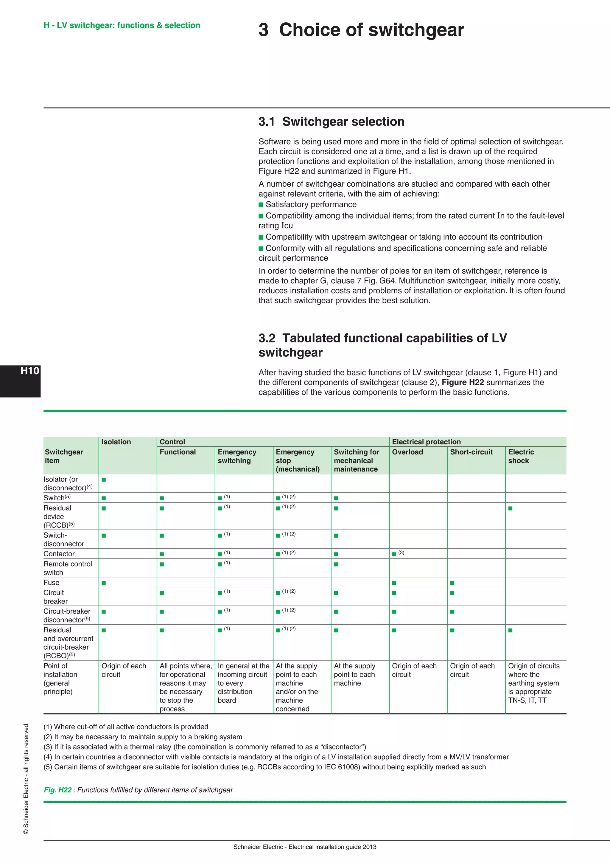
![Schneider Electric - Electrical installation guide 2013
E15
©SchneiderElectric-allrightsreserved
E - Distribution in low-voltage installations
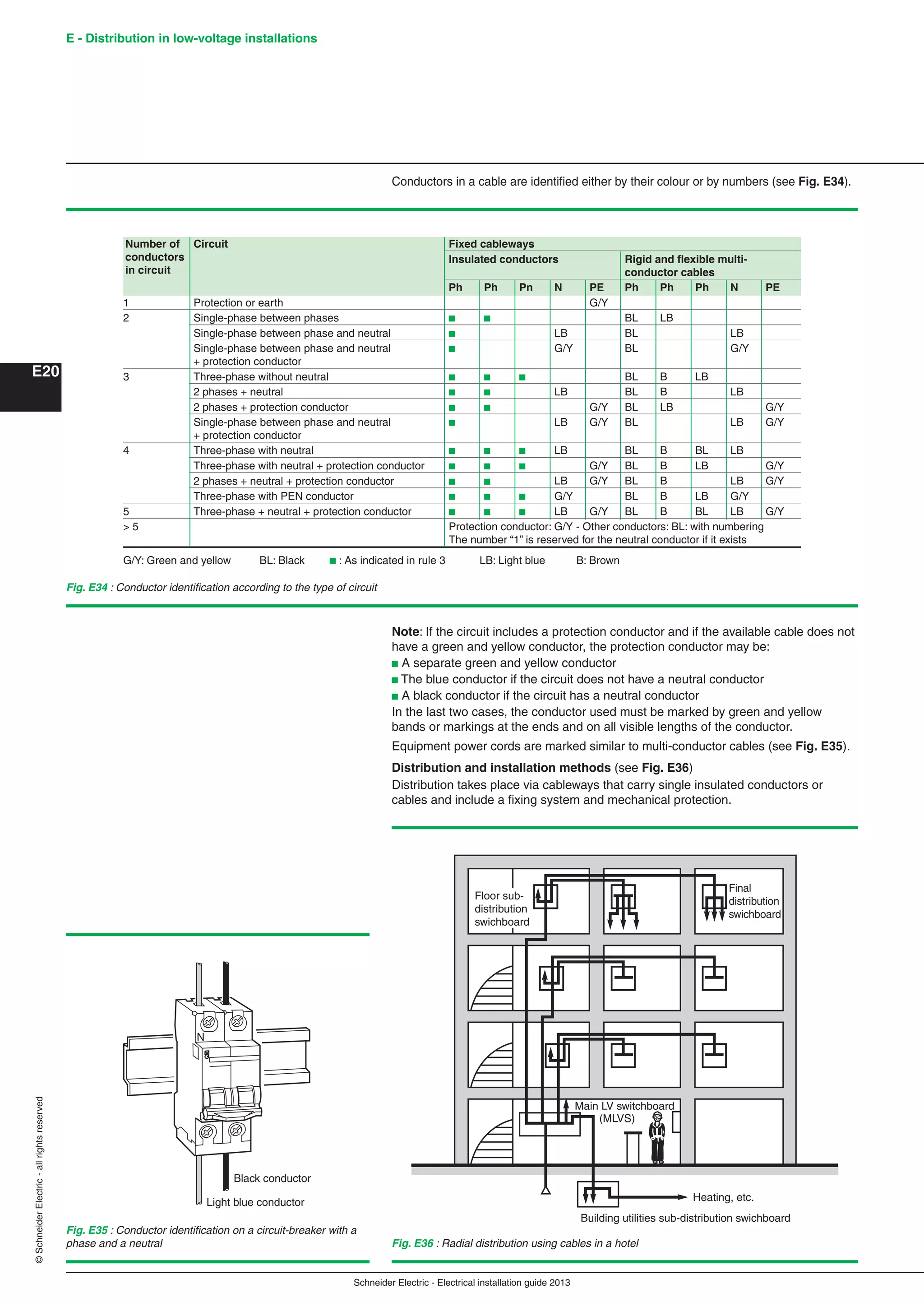
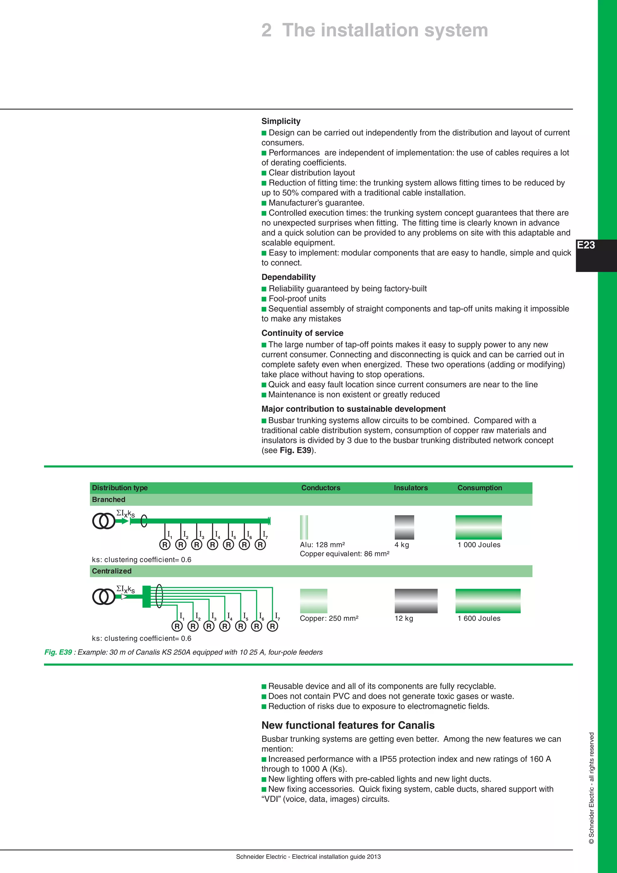
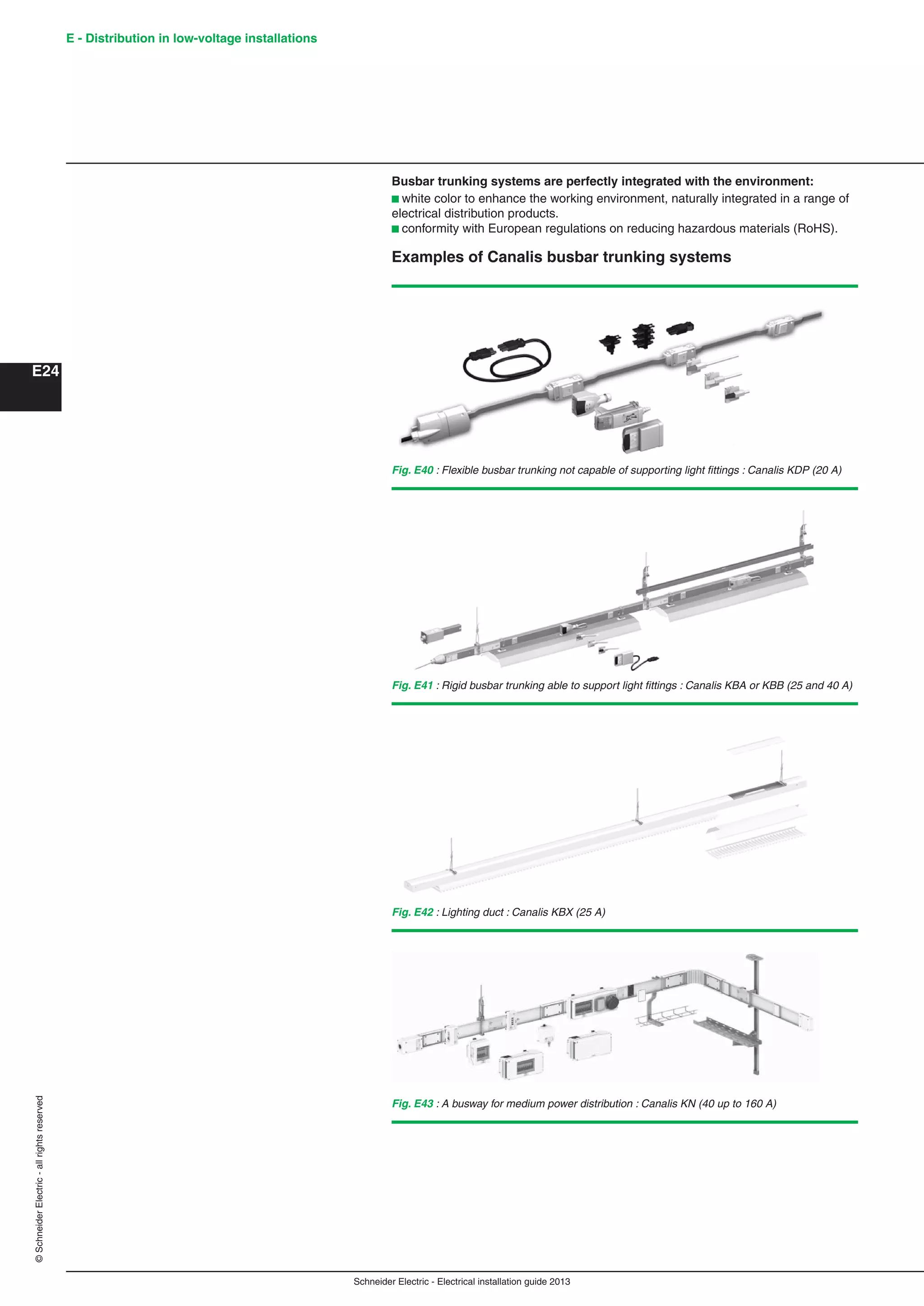
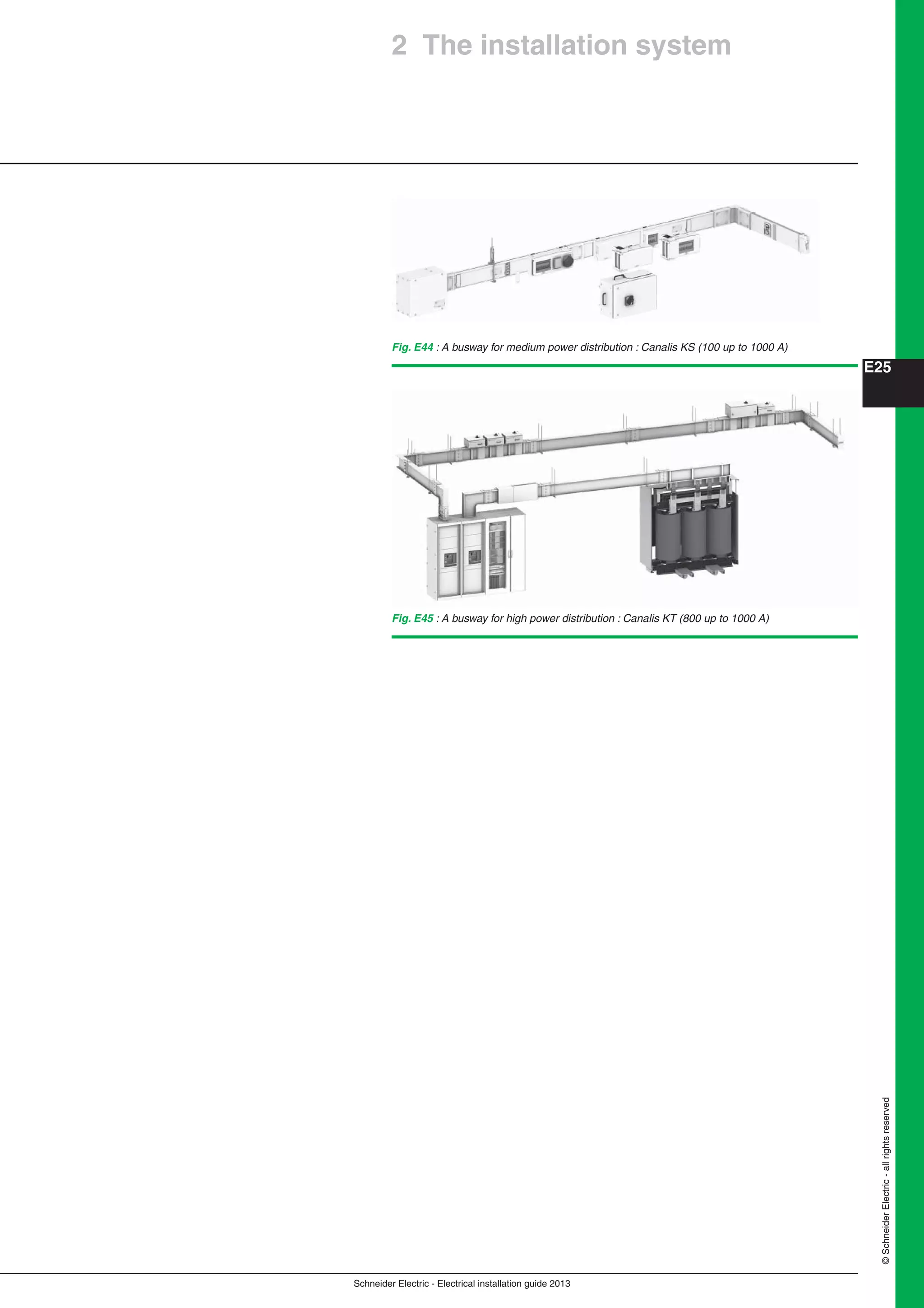
2 The installation system
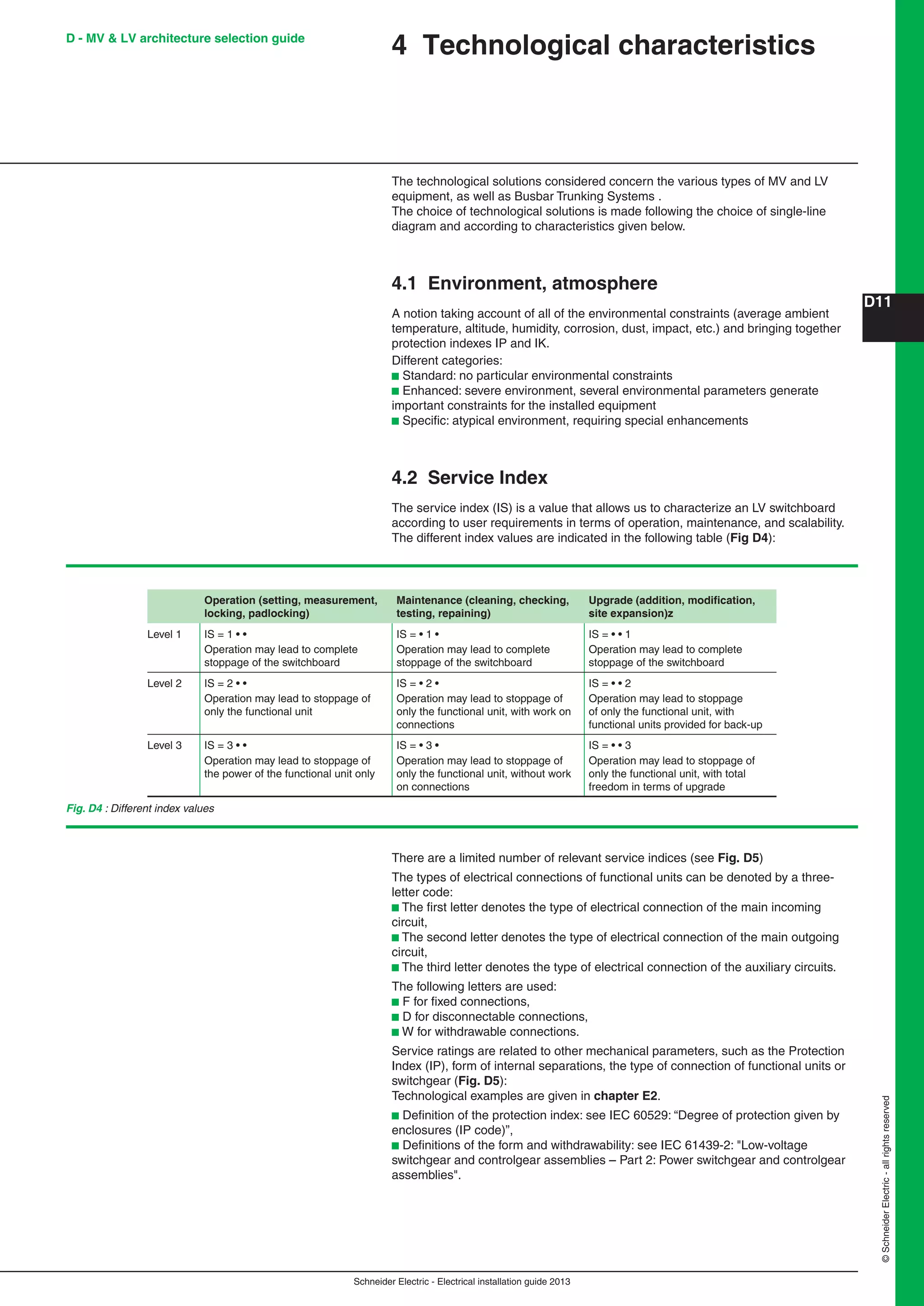
2.1 Distribution switchboards
A distribution switchboard is the point at which an incoming-power supply divides
into separate circuits, each of which is controlled and protected by the fuses or
switchgear of the switchboard. A distribution switchboard is divided into a number
of functional units, each comprising all the electrical and mechanical elements
that contribute to the fulfilment of a given function. It represents a key link in the
dependability chain.
Consequently, the type of distribution switchboard must be perfectly adapted to its
application. Its design and construction must comply with applicable standards and
working practises.
The distribution switchboard enclosure provides dual protection:
b Protection of switchgear, indicating instruments, relays, fusegear, etc. against
mechanical impacts, vibrations and other external influences likely to interfere with
operational integrity (EMI, dust, moisture, vermin, etc.)
b The protection of human life against the possibility of direct and indirect electric
shock (see degree of protection IP and the IK index in section 3.3 of Chapter E).
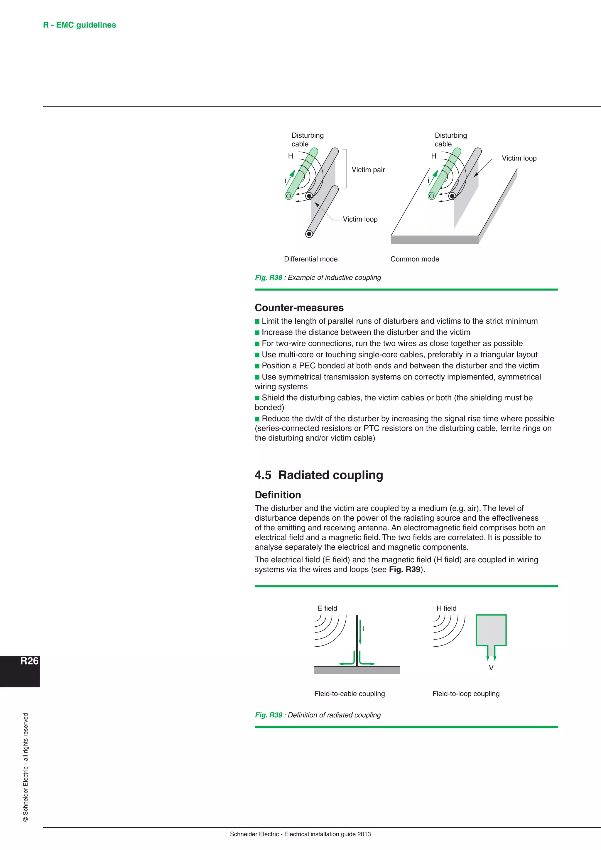
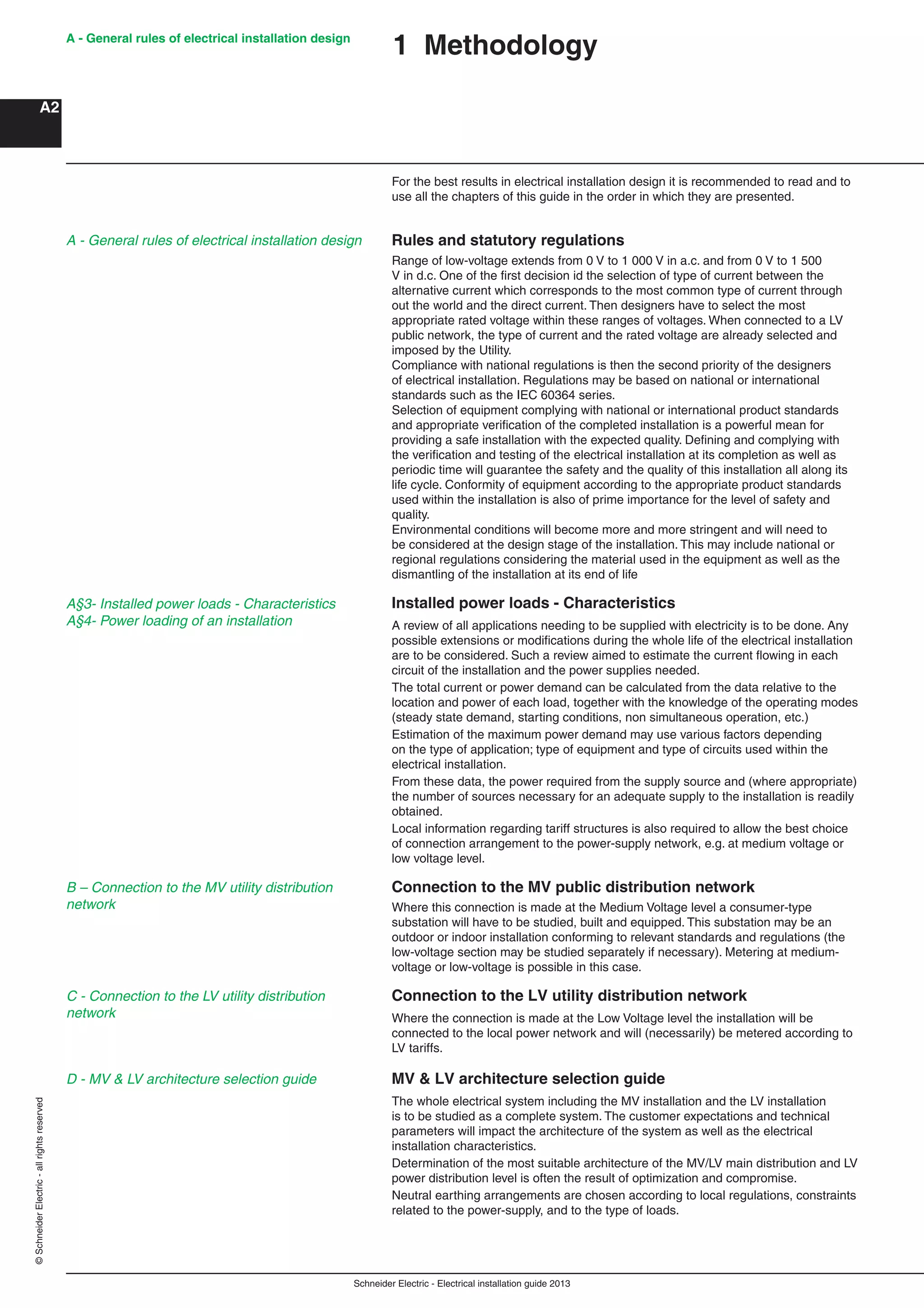
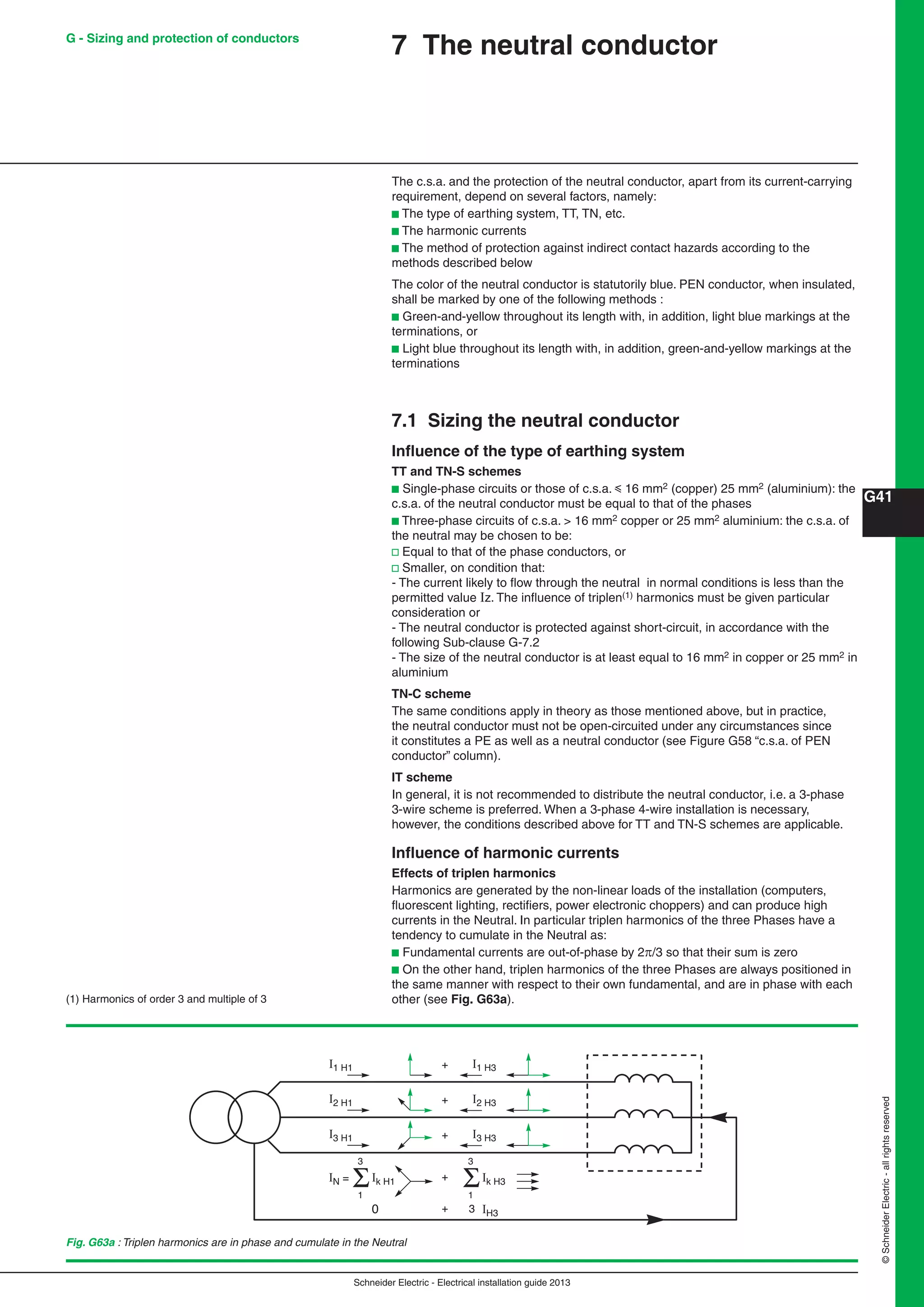
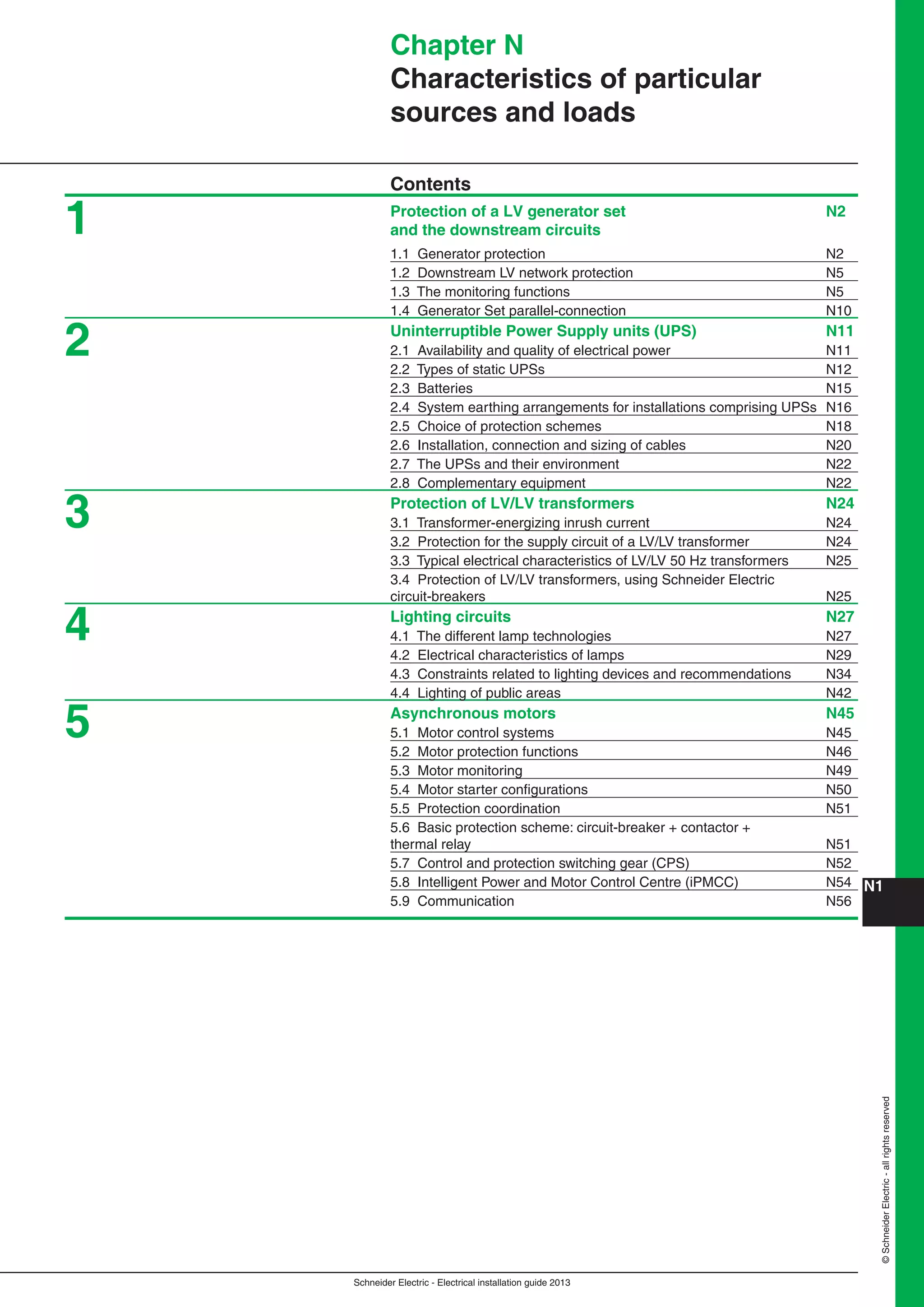
Types of distribution switchboards
Distribution switchboards may differ according to the kind of application and the
design principle adopted (notably in the arrangement of the busbars).
Distribution switchboards according to specific applications
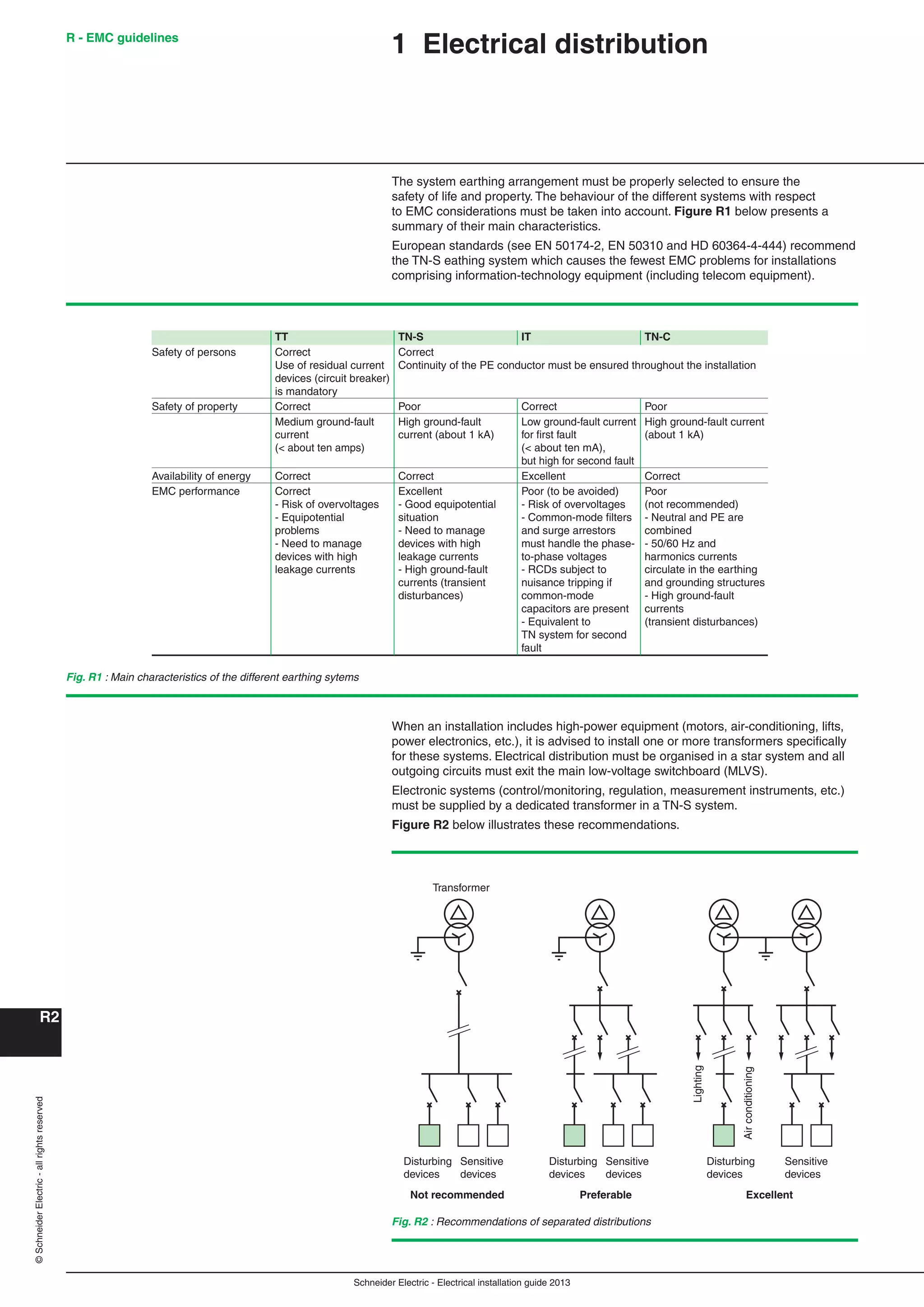
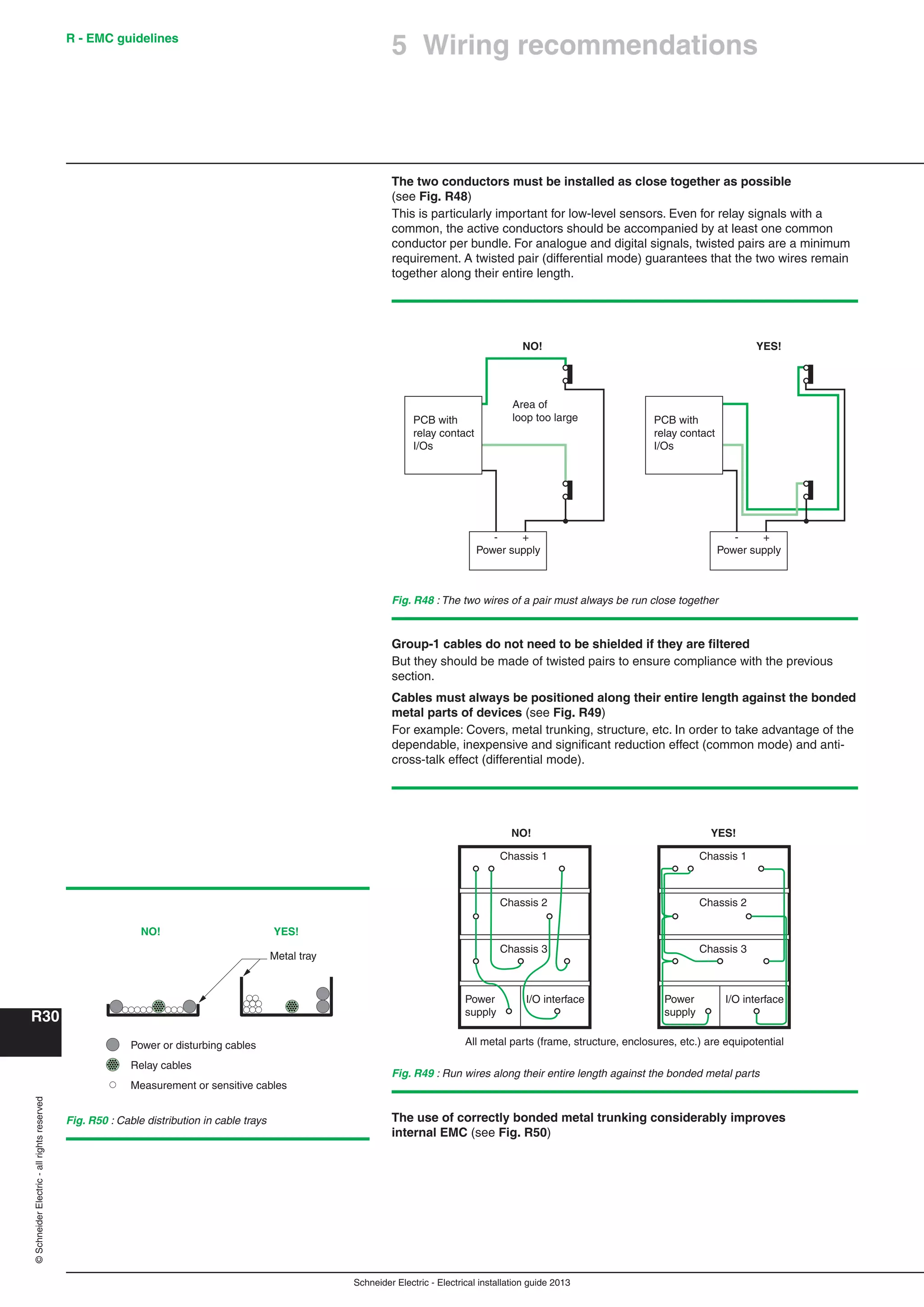
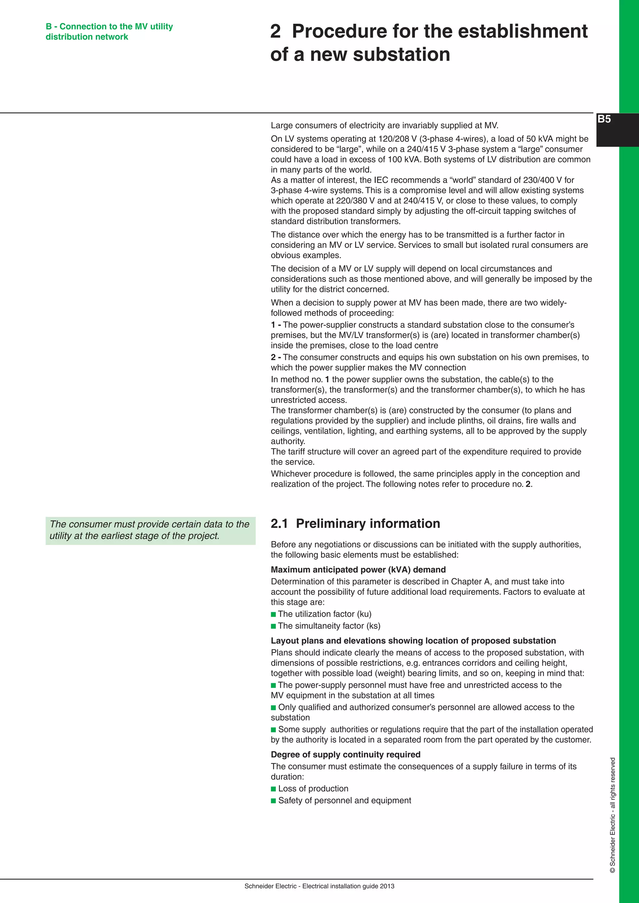
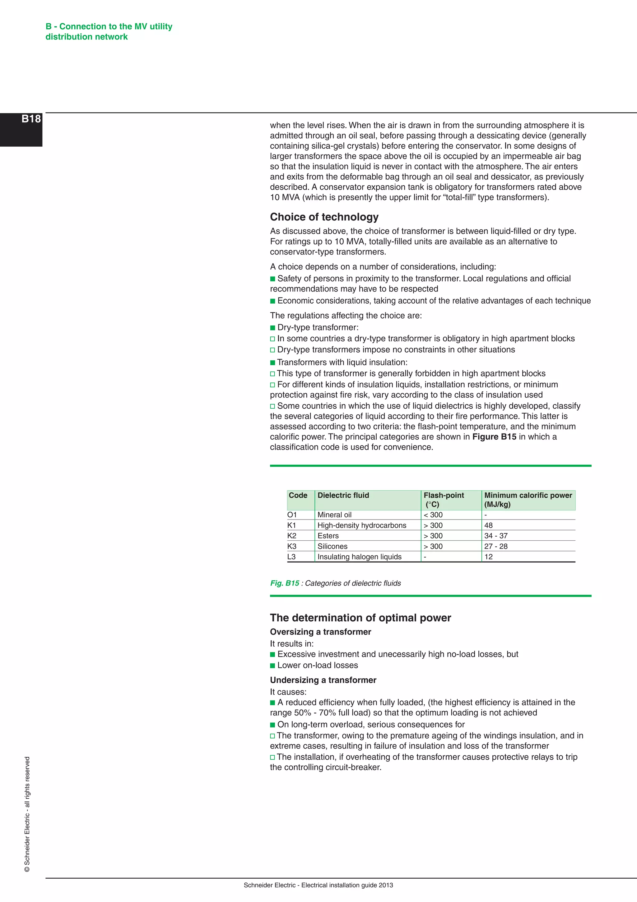
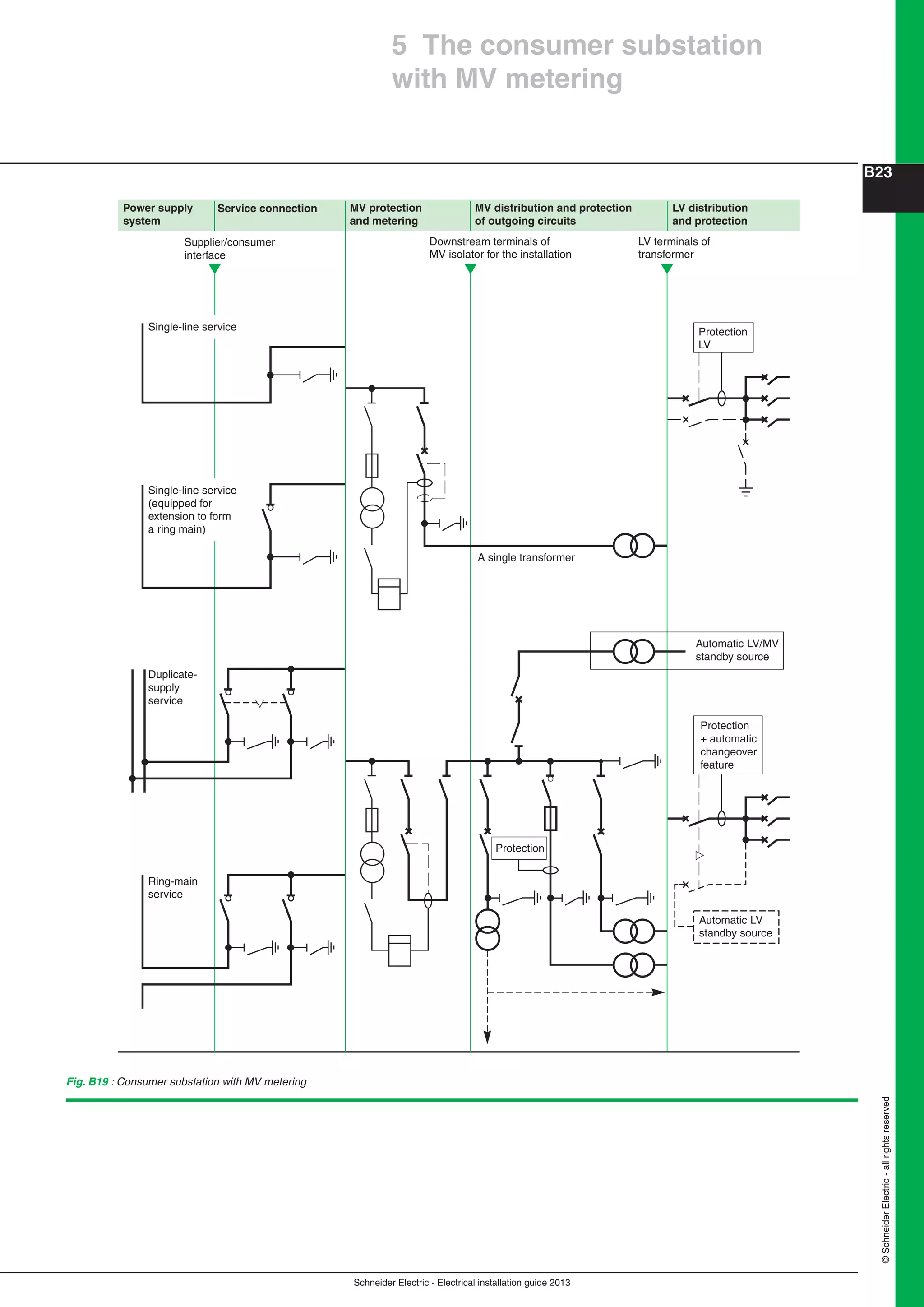
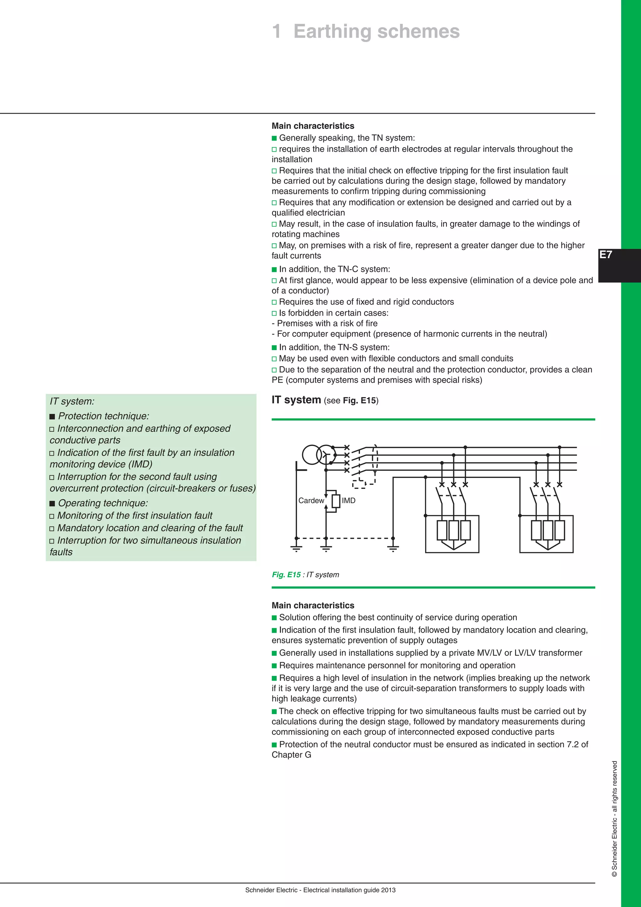
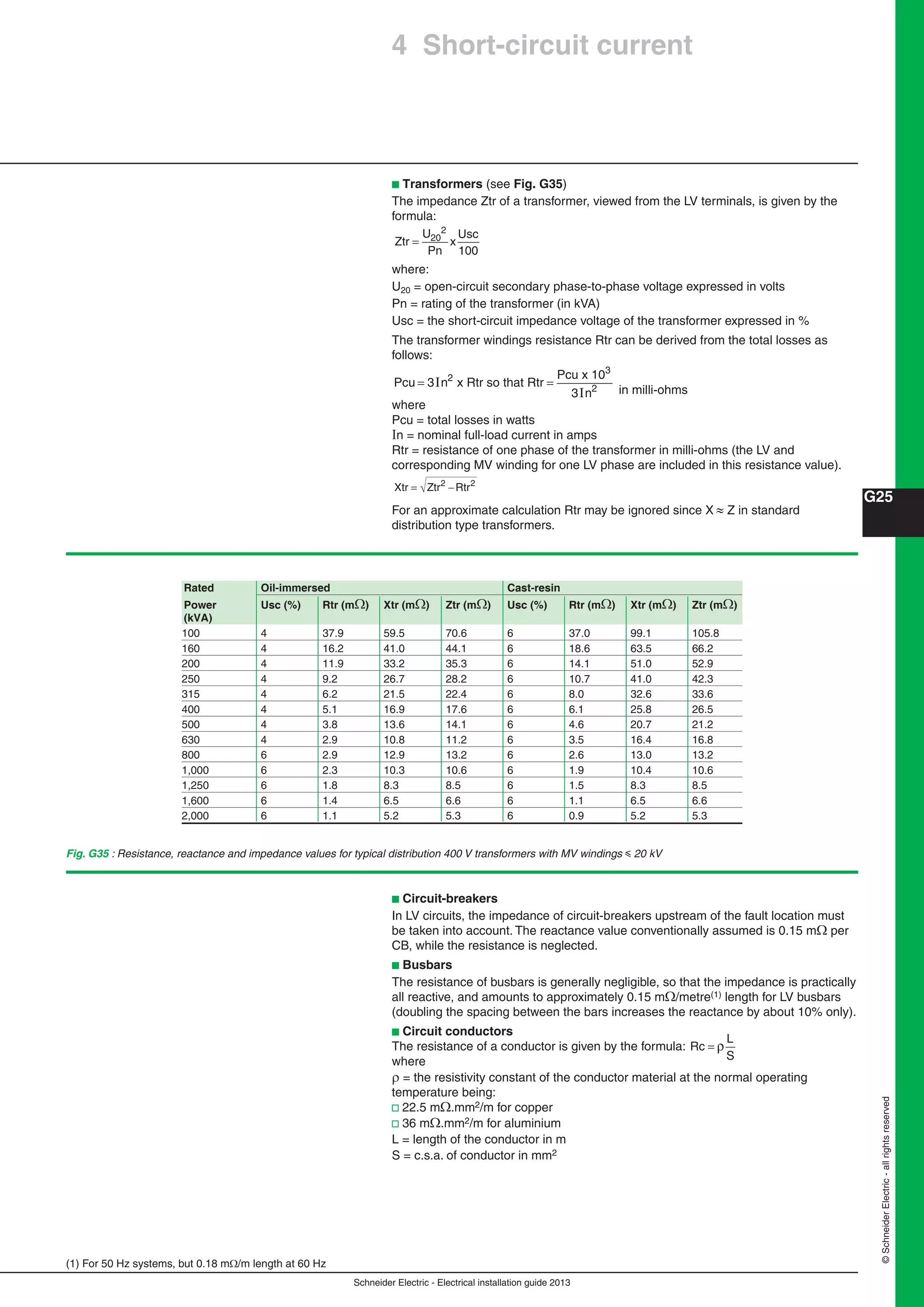
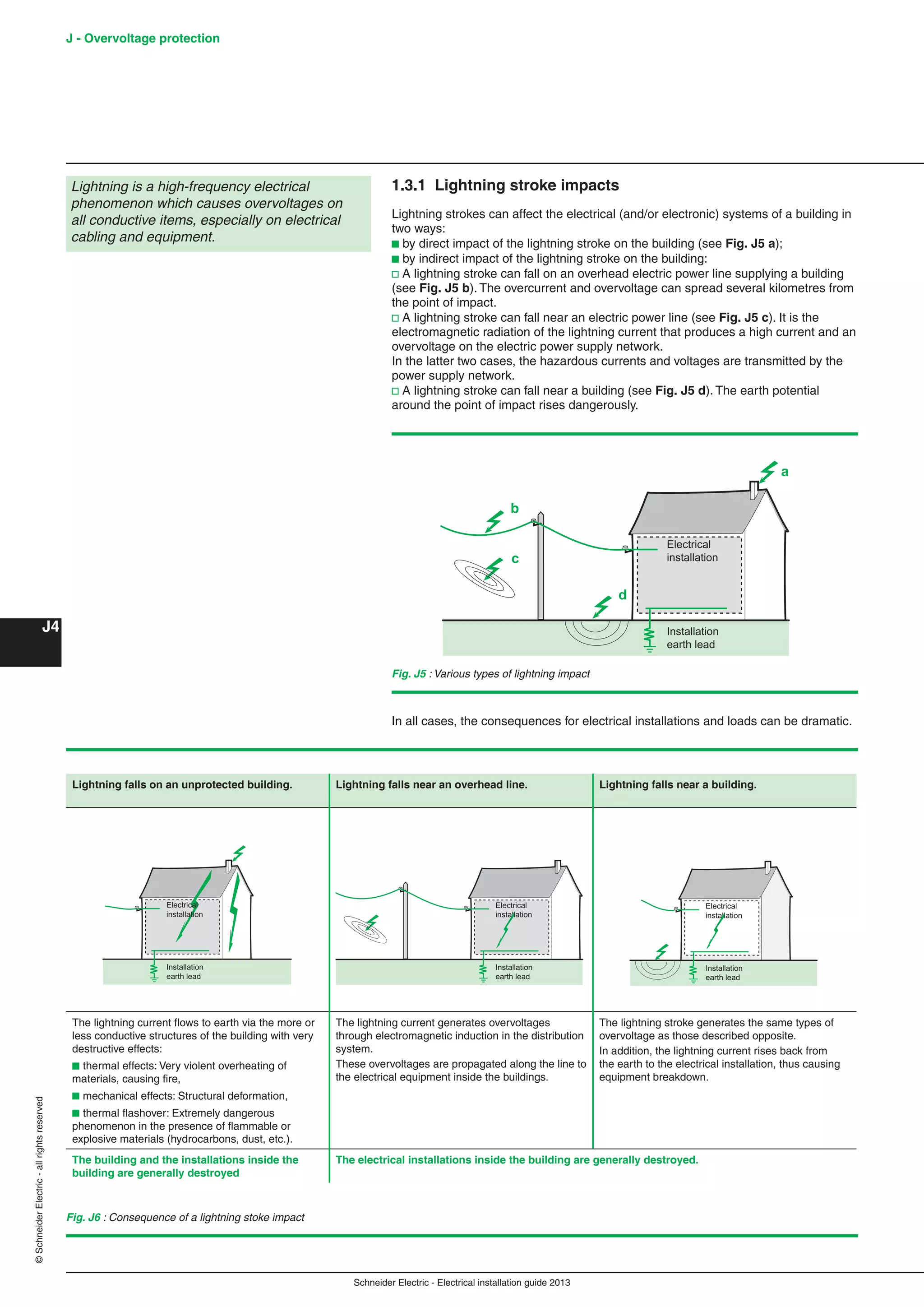
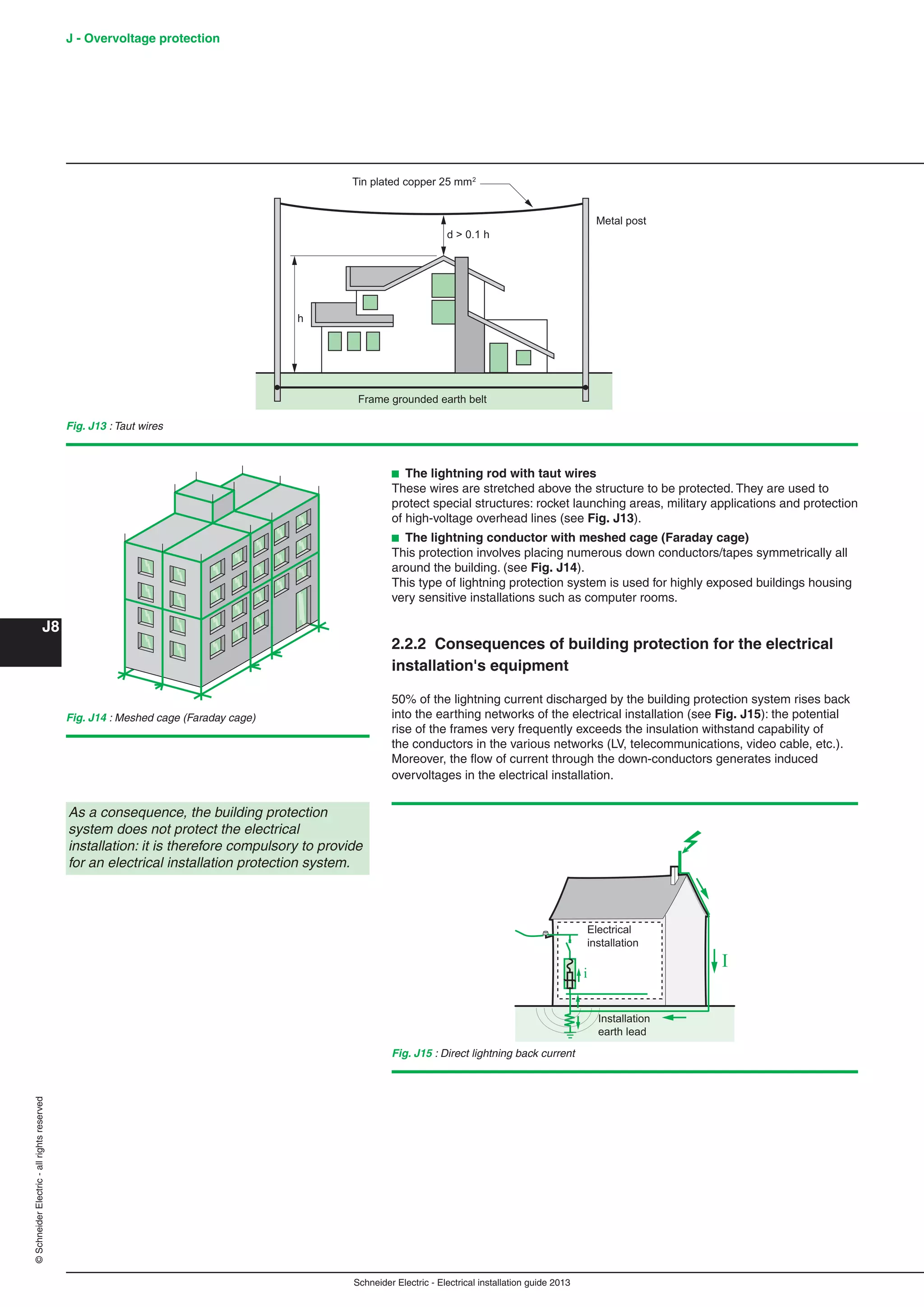
The principal types of distribution switchboards are:
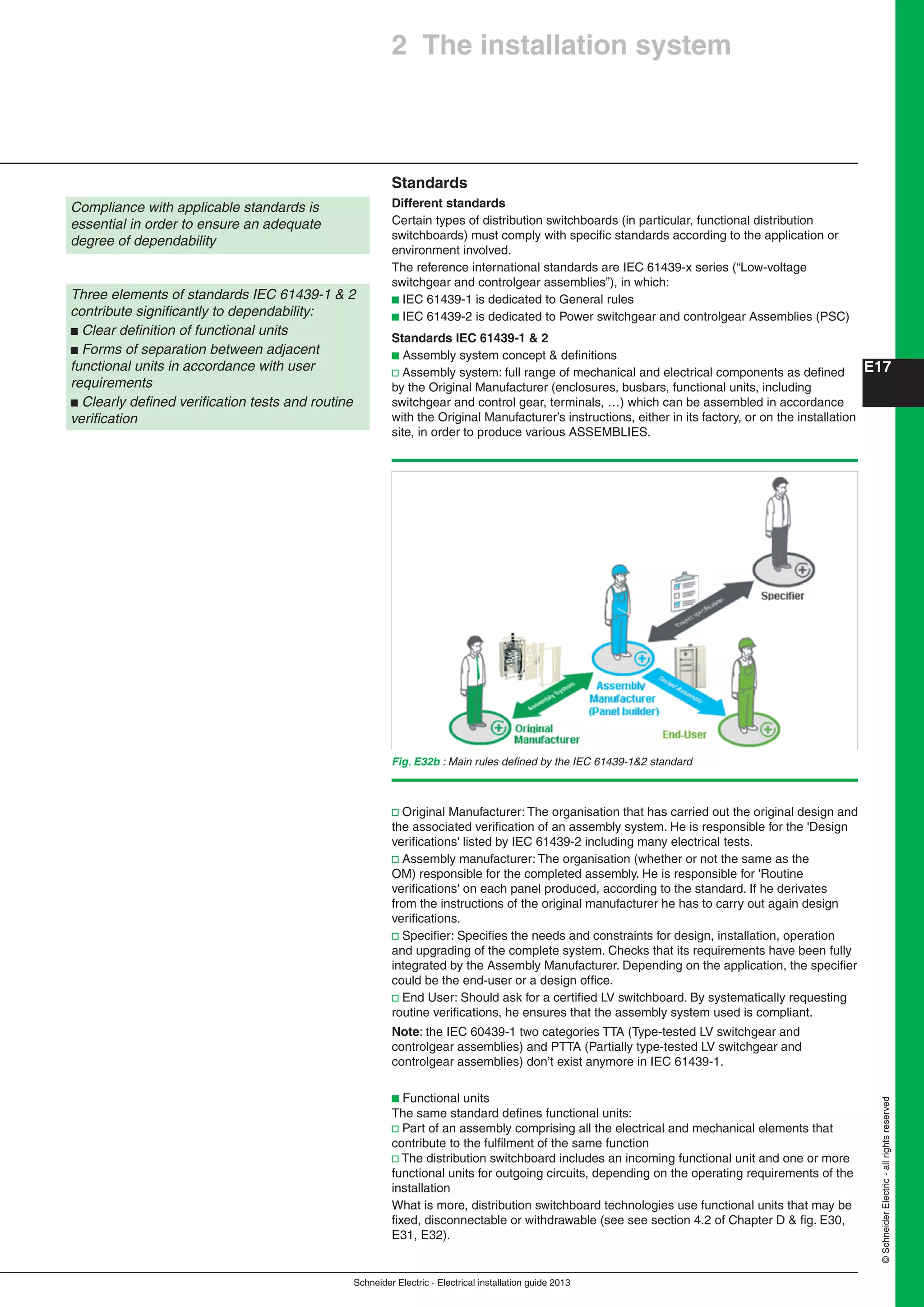
b The main LV switchboard - MLVS - (see Fig. E27a)
b Motor control centres - MCC - (see Fig. E27b)
b Sub-distribution switchboards (see Fig. E28)
b Final distribution switchboards (see Fig. E29)
Distribution switchboards for specific applications (e.g. heating, lifts, industrial
processes) can be located:
b Adjacent to the main LV switchboard, or
b Near the application concerned
Sub-distribution and final distribution switchboards are generally distributed
throughout the site.
Distribution switchboards, including the main
LV switchboard (MLVS), are critical to the
dependability of an electrical installation.
They must comply with well-defined standards
governing the design and construction of
LV switchgear assemblies
The load requirements dictate the type of
distribution switchboard to be installed
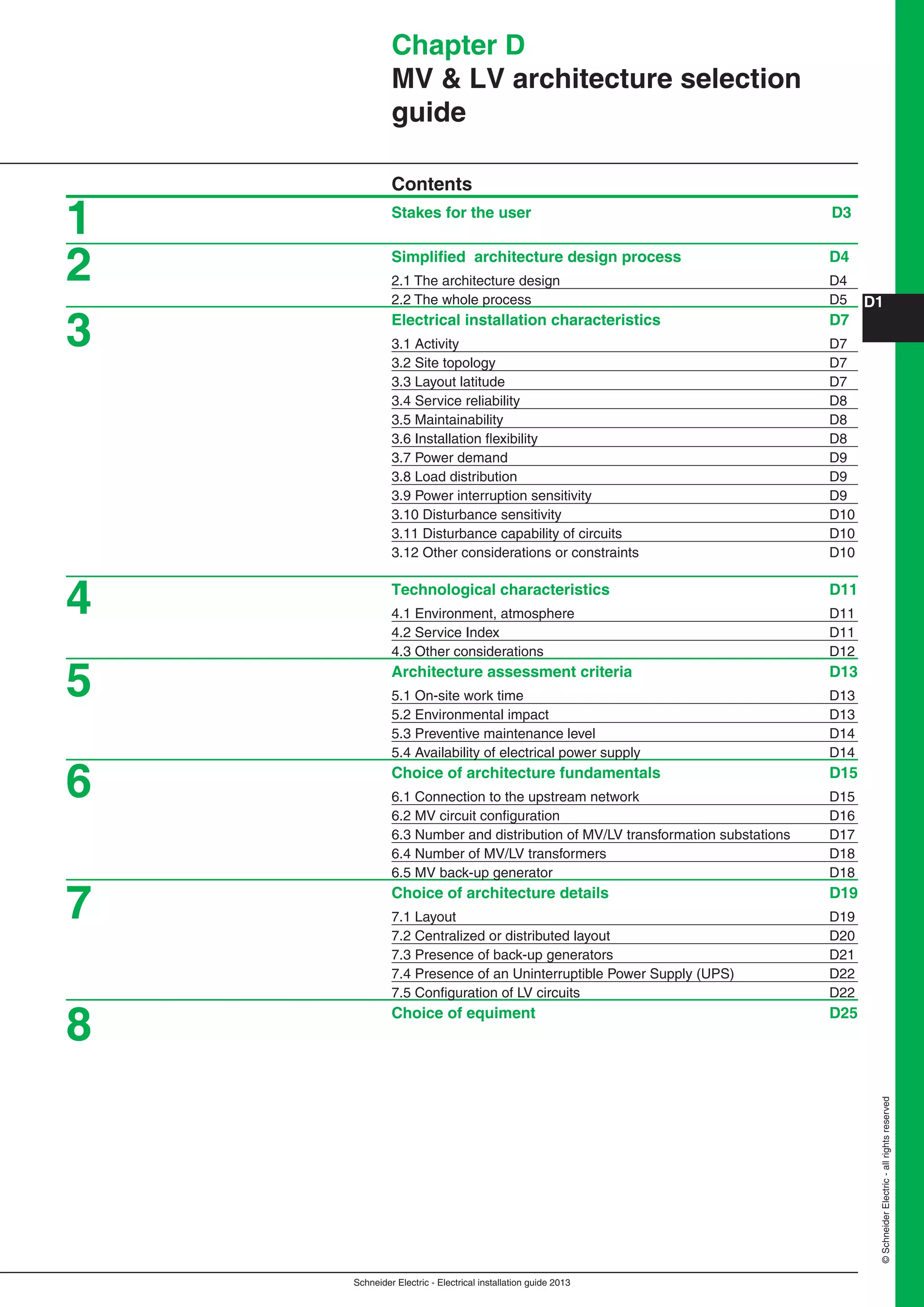
Fig. E27 : [a] A main LV switchboard - MLVS - (Prisma Plus P) with incoming circuits in the form
of busways - [b] A LV motor control centre - MCC - (Okken)
Fig. E28 : A sub-distribution switchboard (Prisma Plus G) Fig. E29 : Final distribution switchboards [a] Prisma Plus G Pack; [b] Kaedra; [c] mini-Pragma
a b c
a b](https://image.slidesharecdn.com/manualinstalacioneselectricas-150309124103-conversion-gate01/75/Manual-instalaciones-electricas-131-2048.jpg)


![Schneider Electric - Electrical installation guide 2013
N21©SchneiderElectric-allrightsreserved
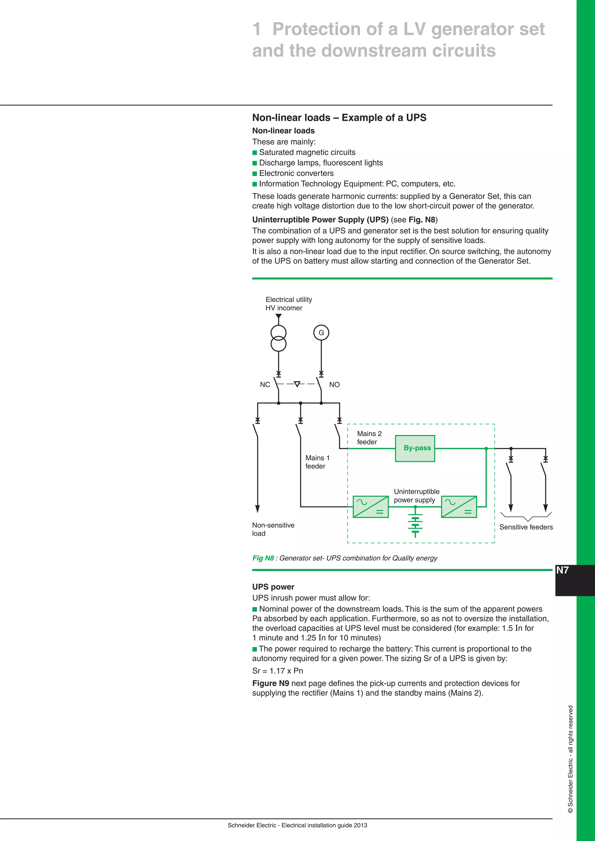
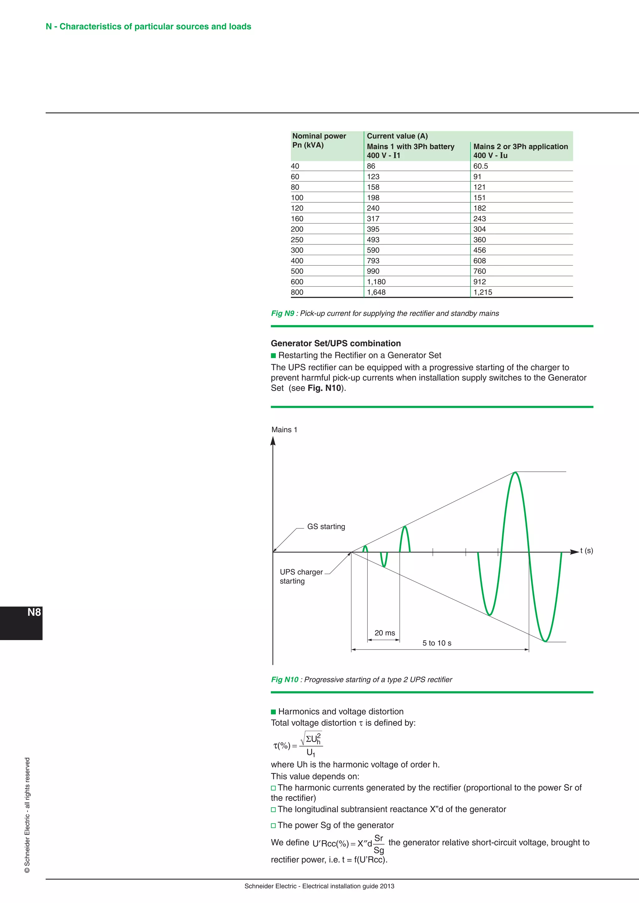
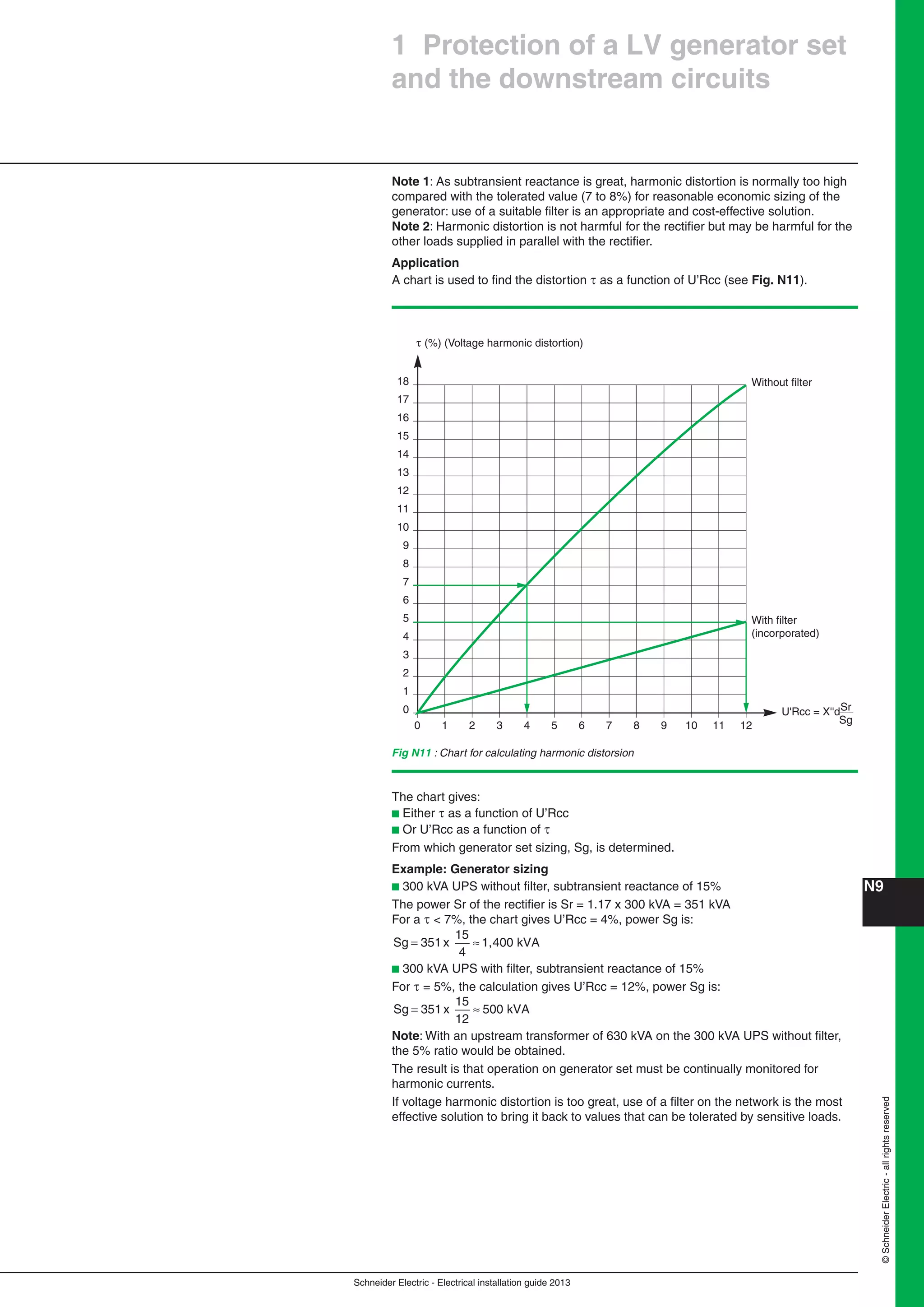
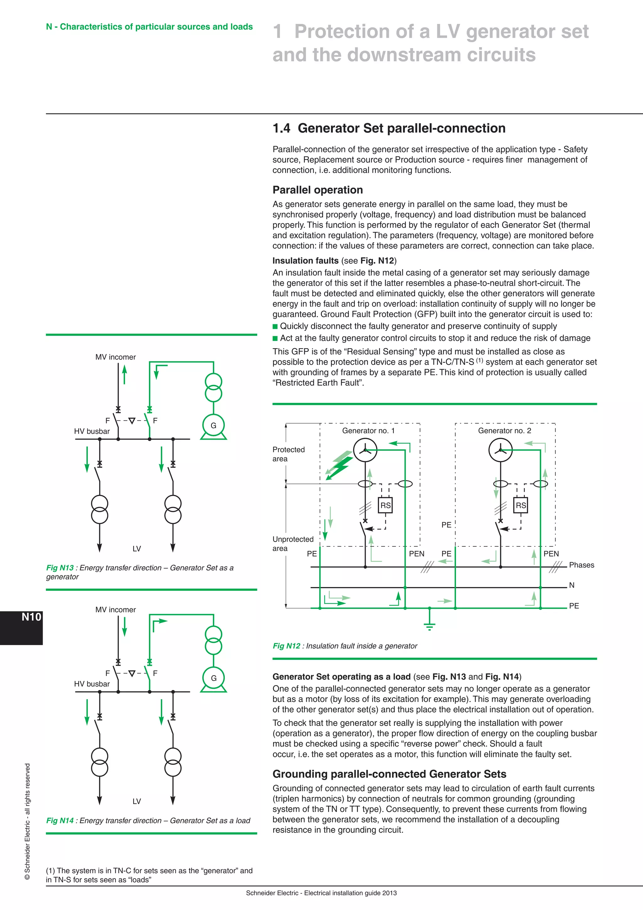
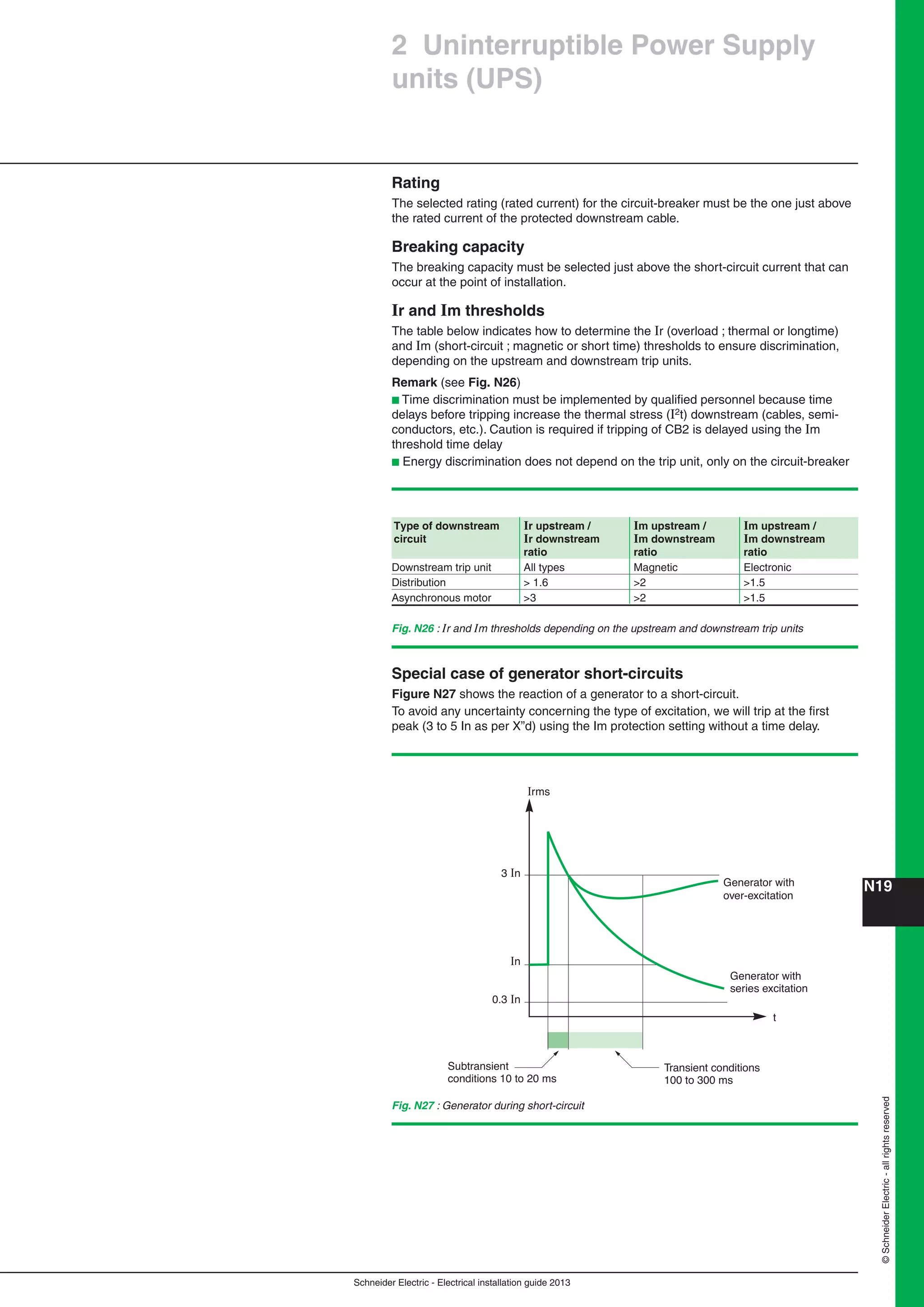
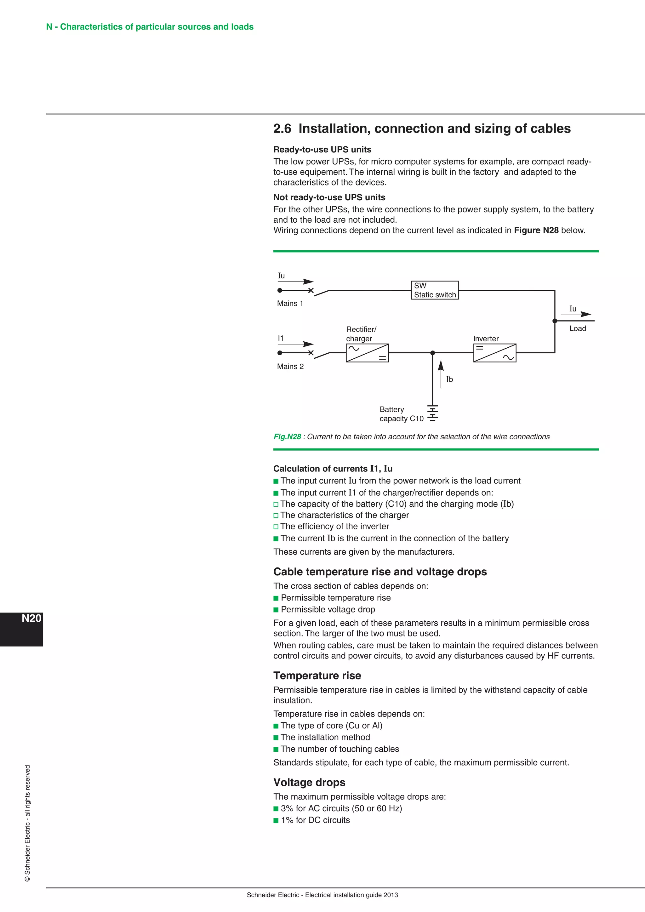
2 Uninterruptible Power Supply
units (UPS)
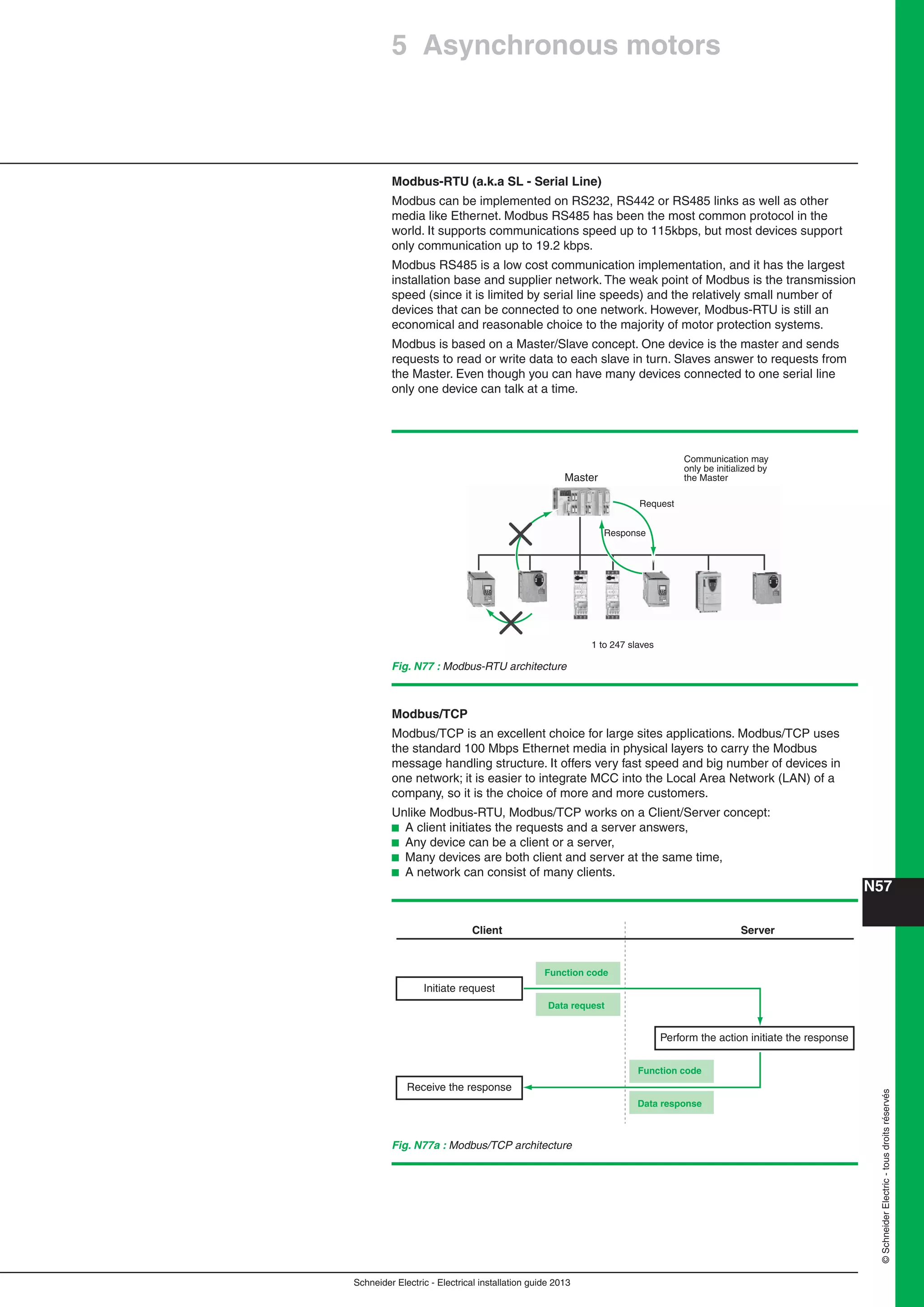
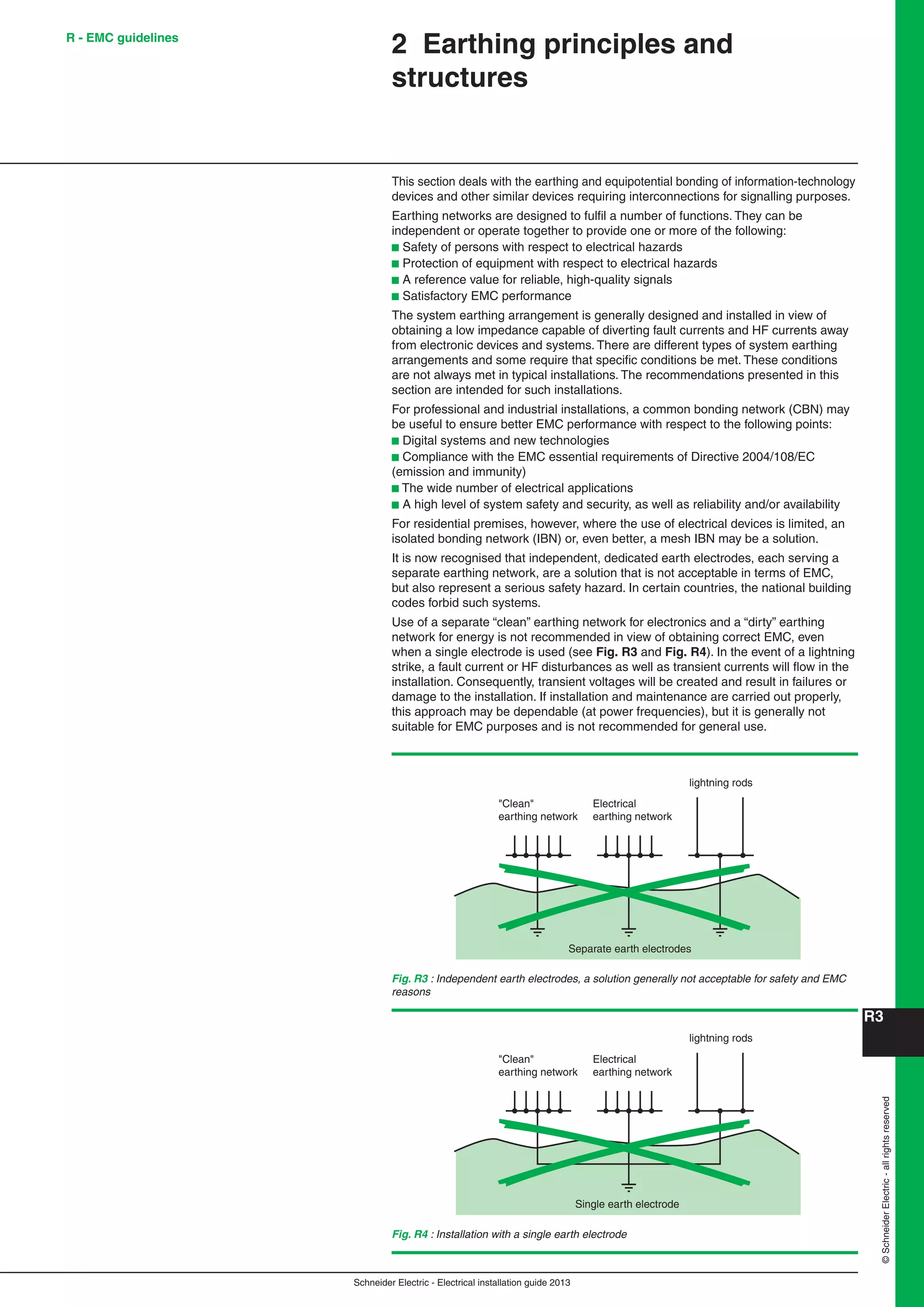
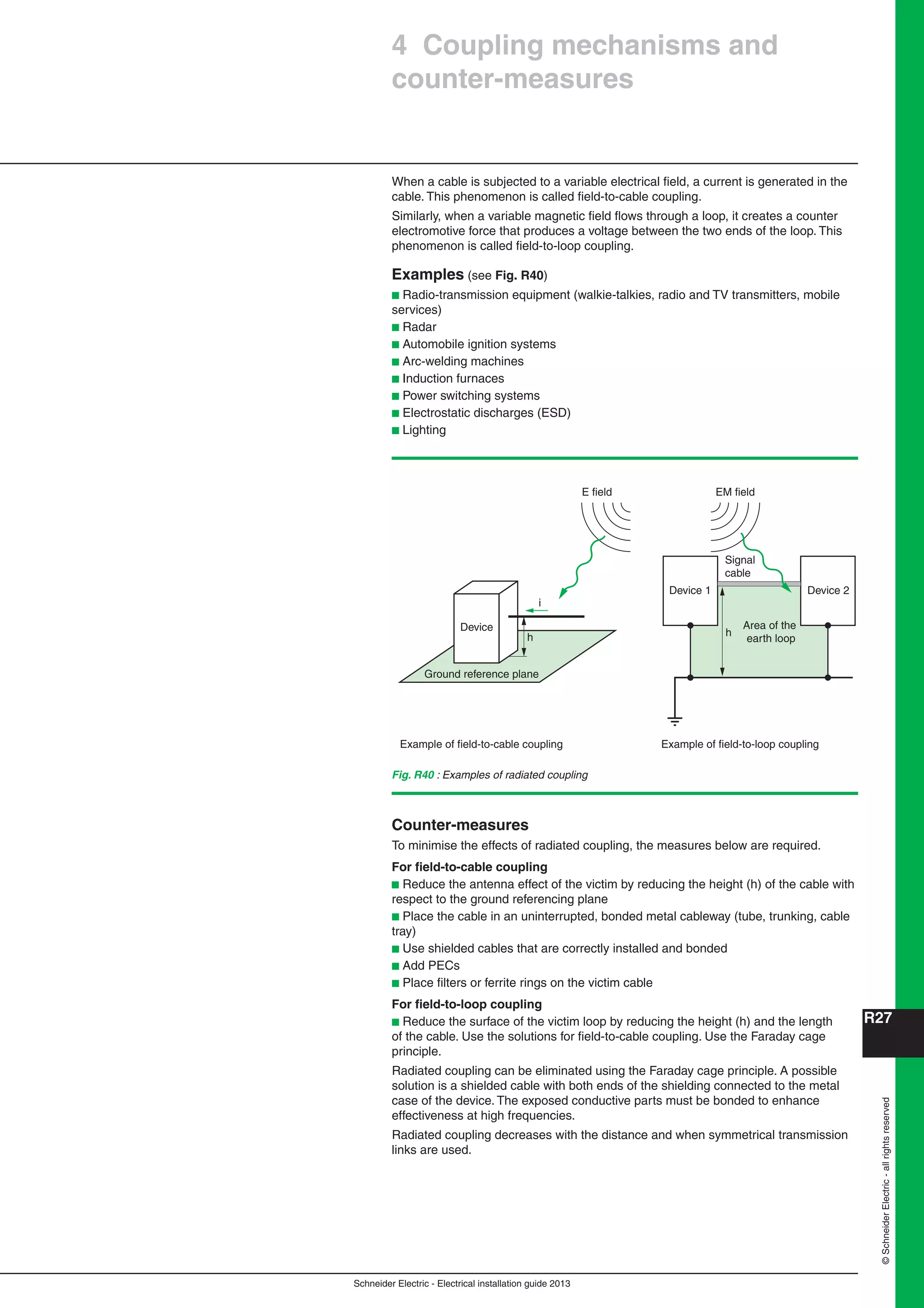
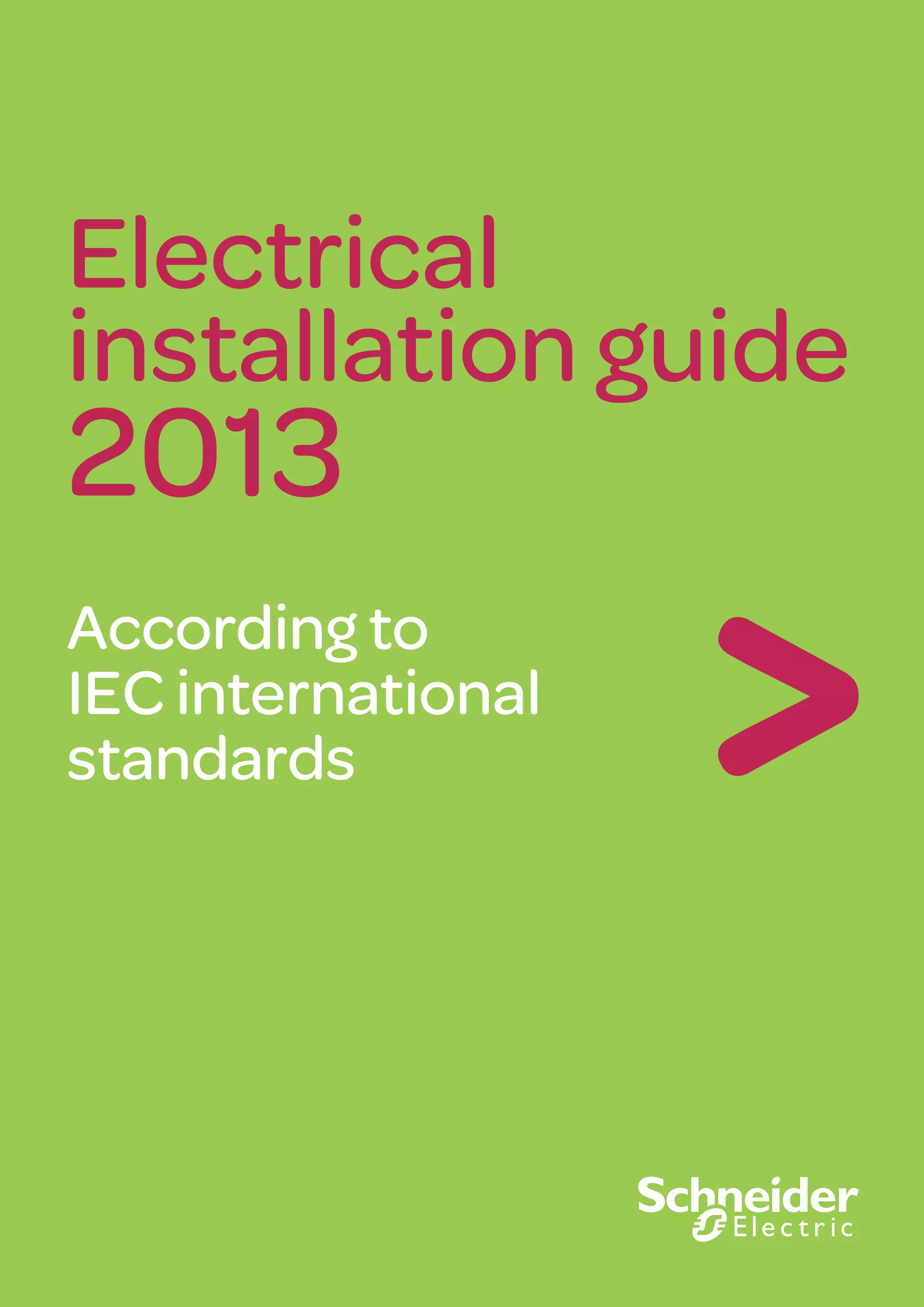
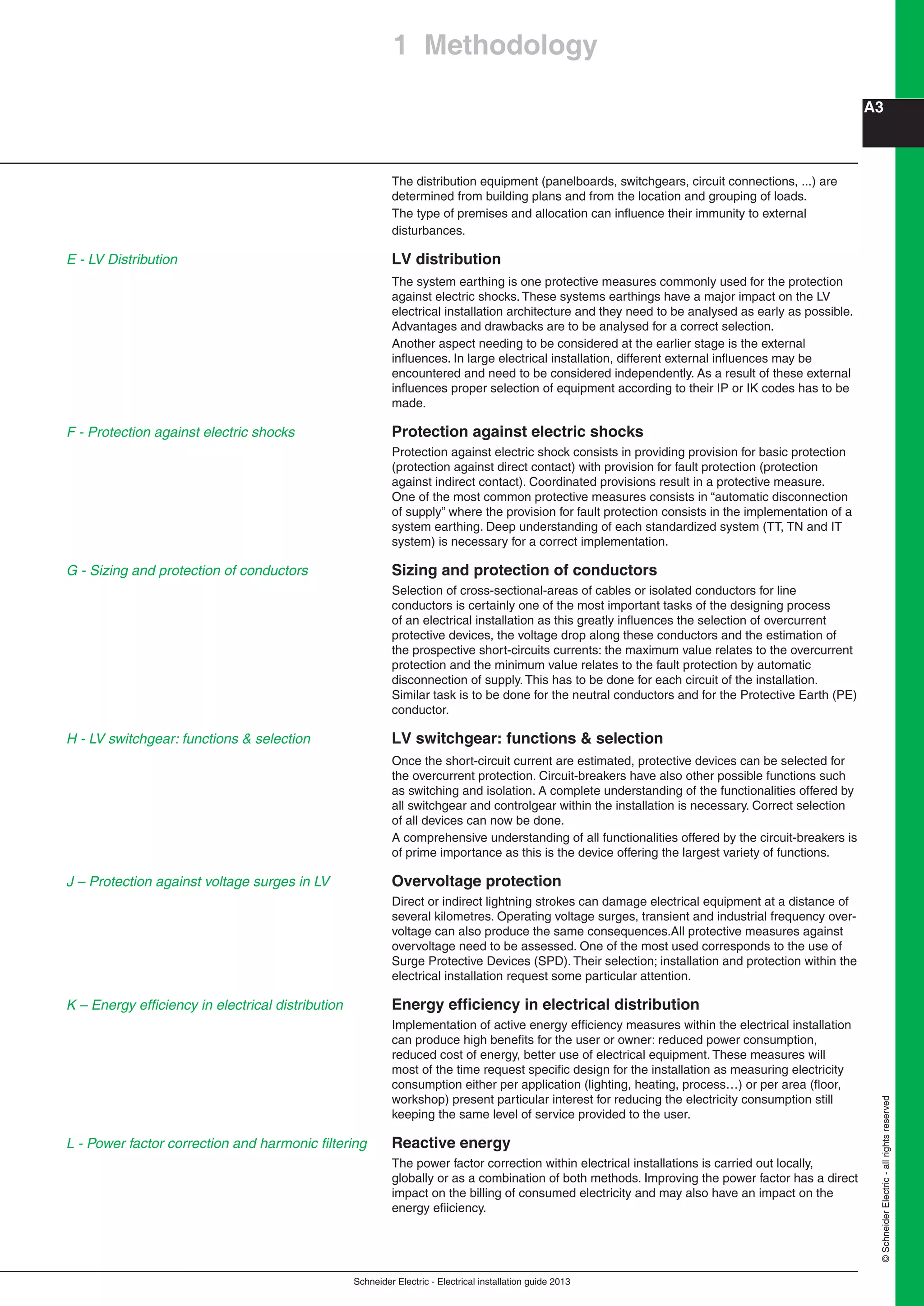
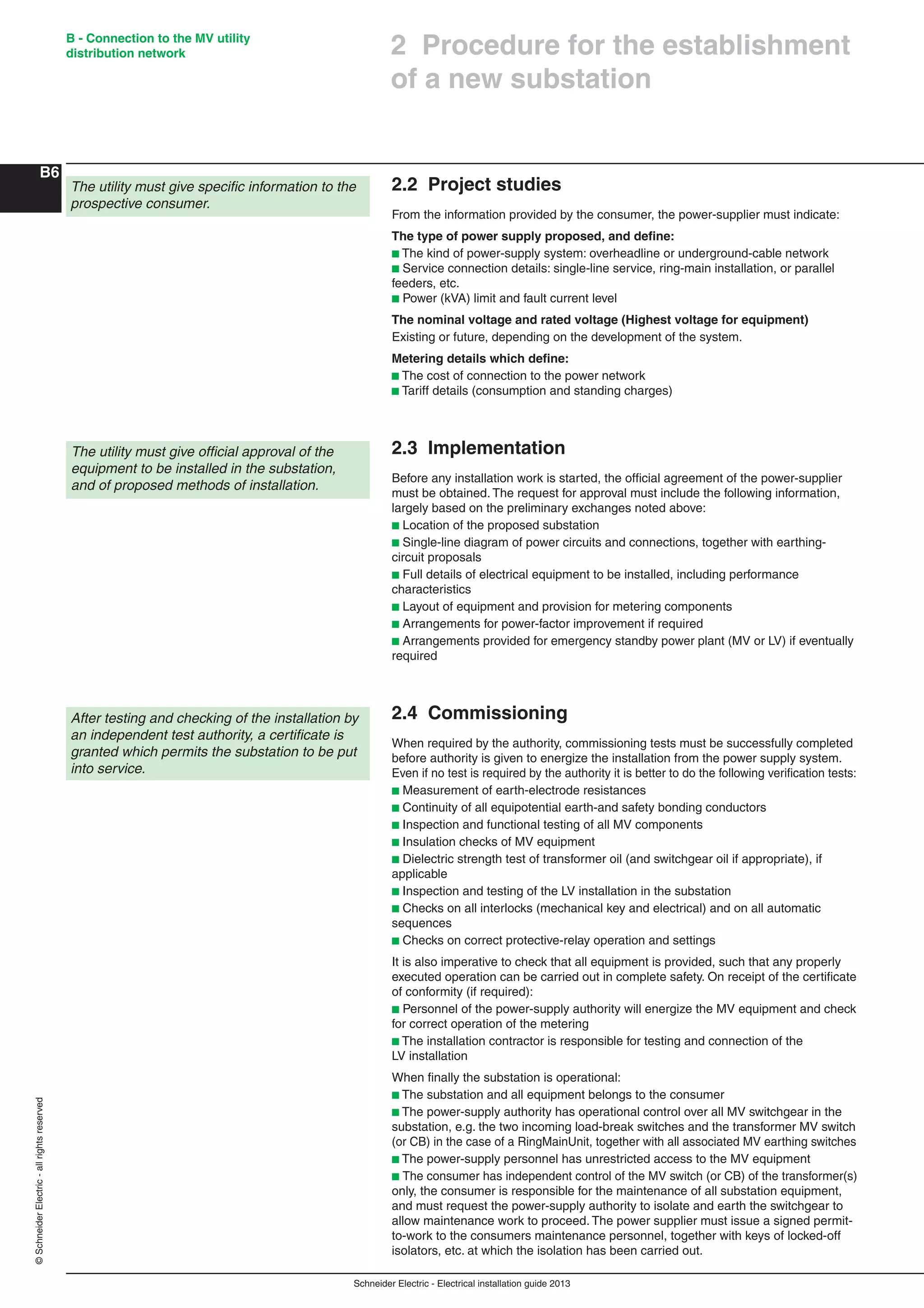
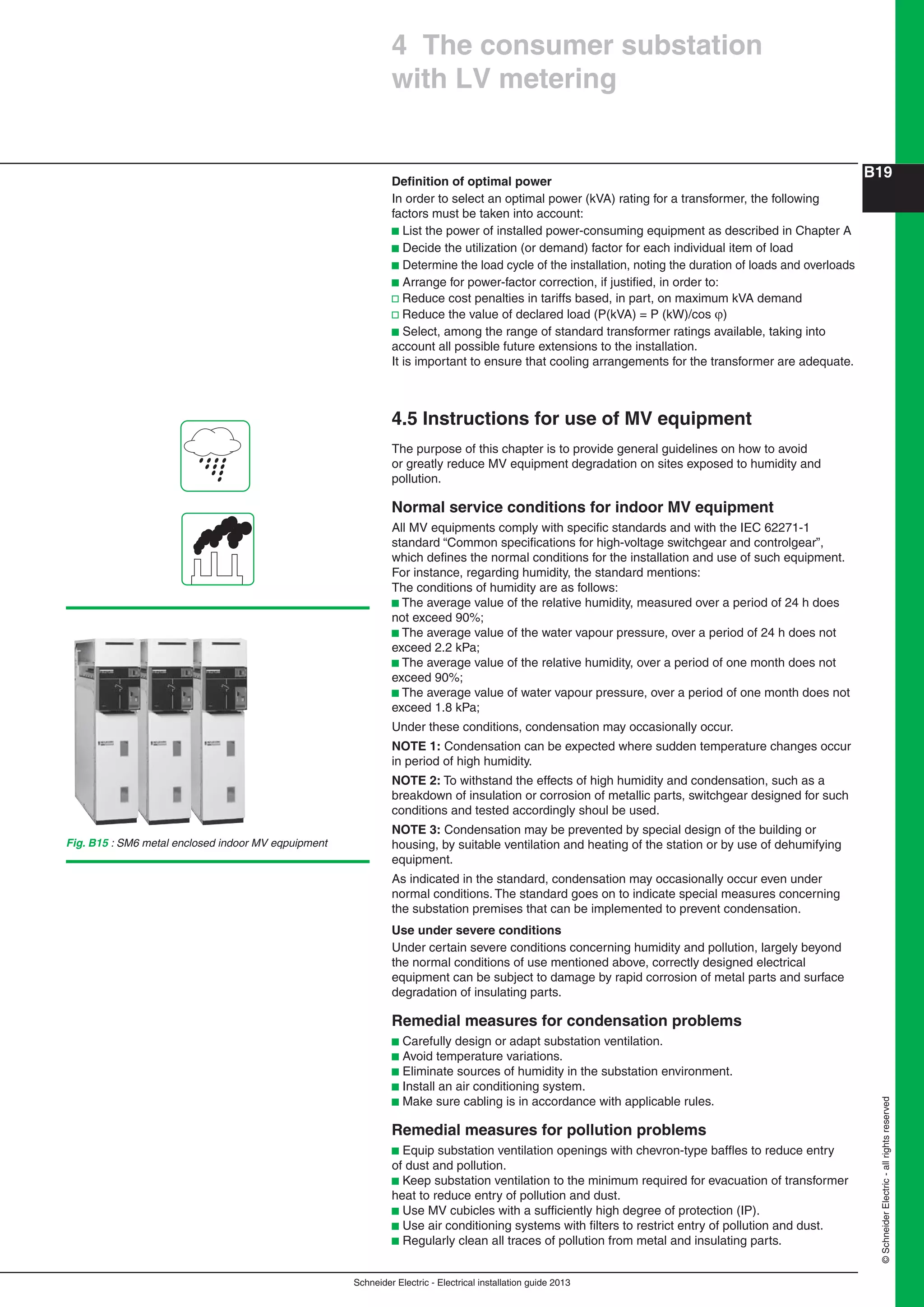
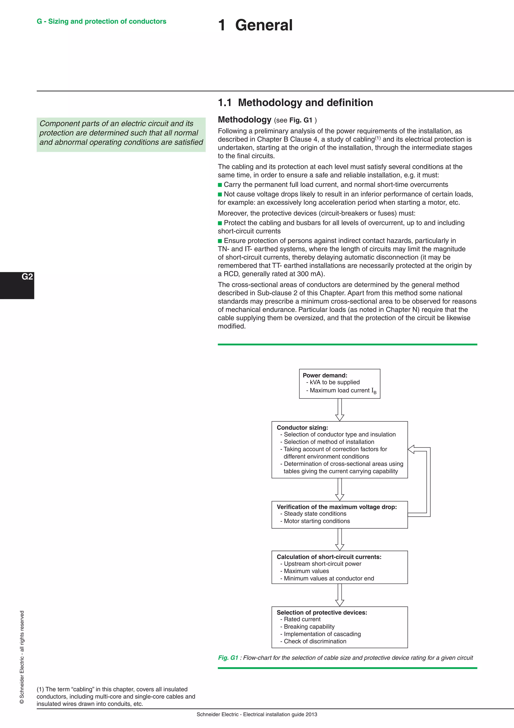
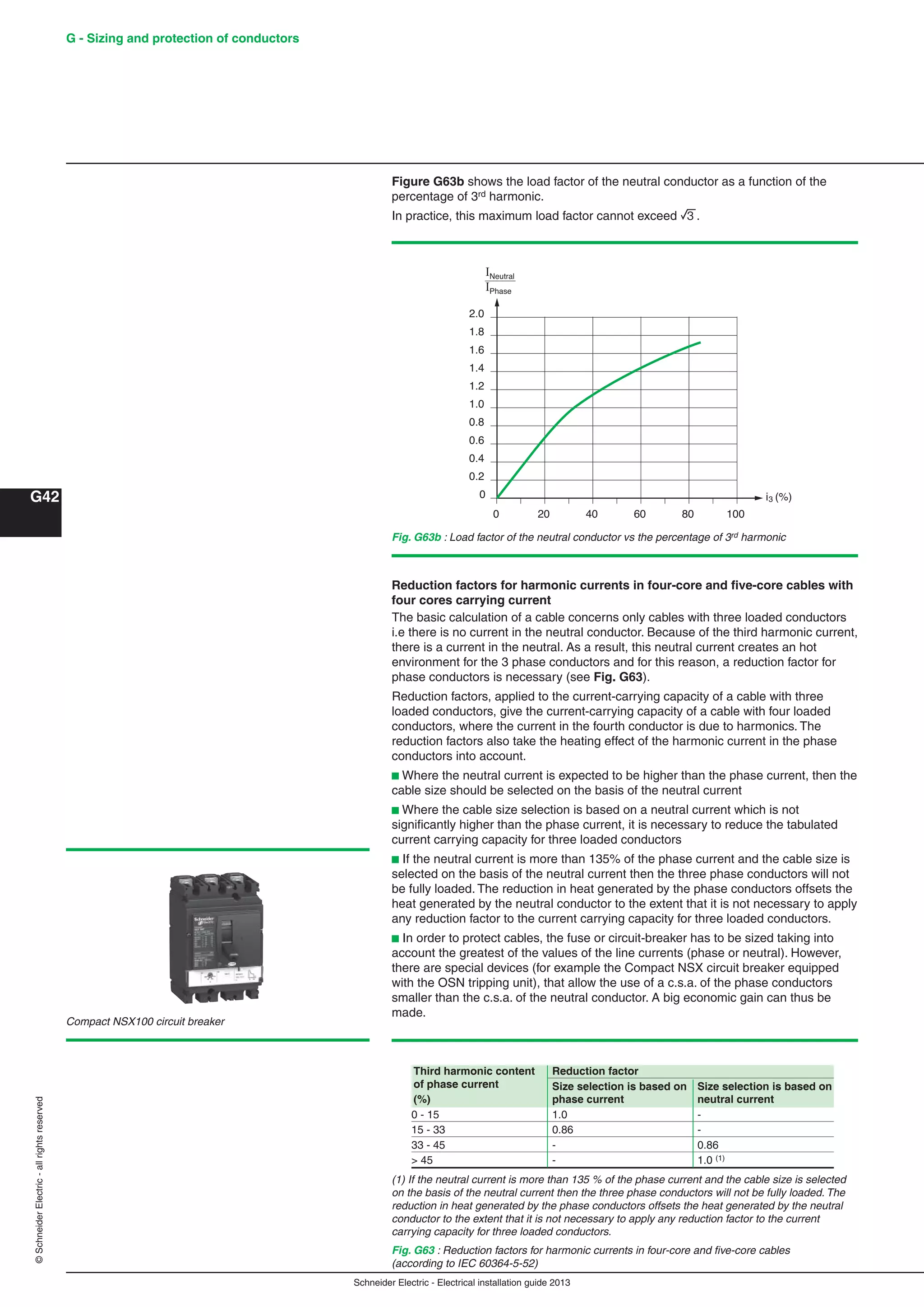
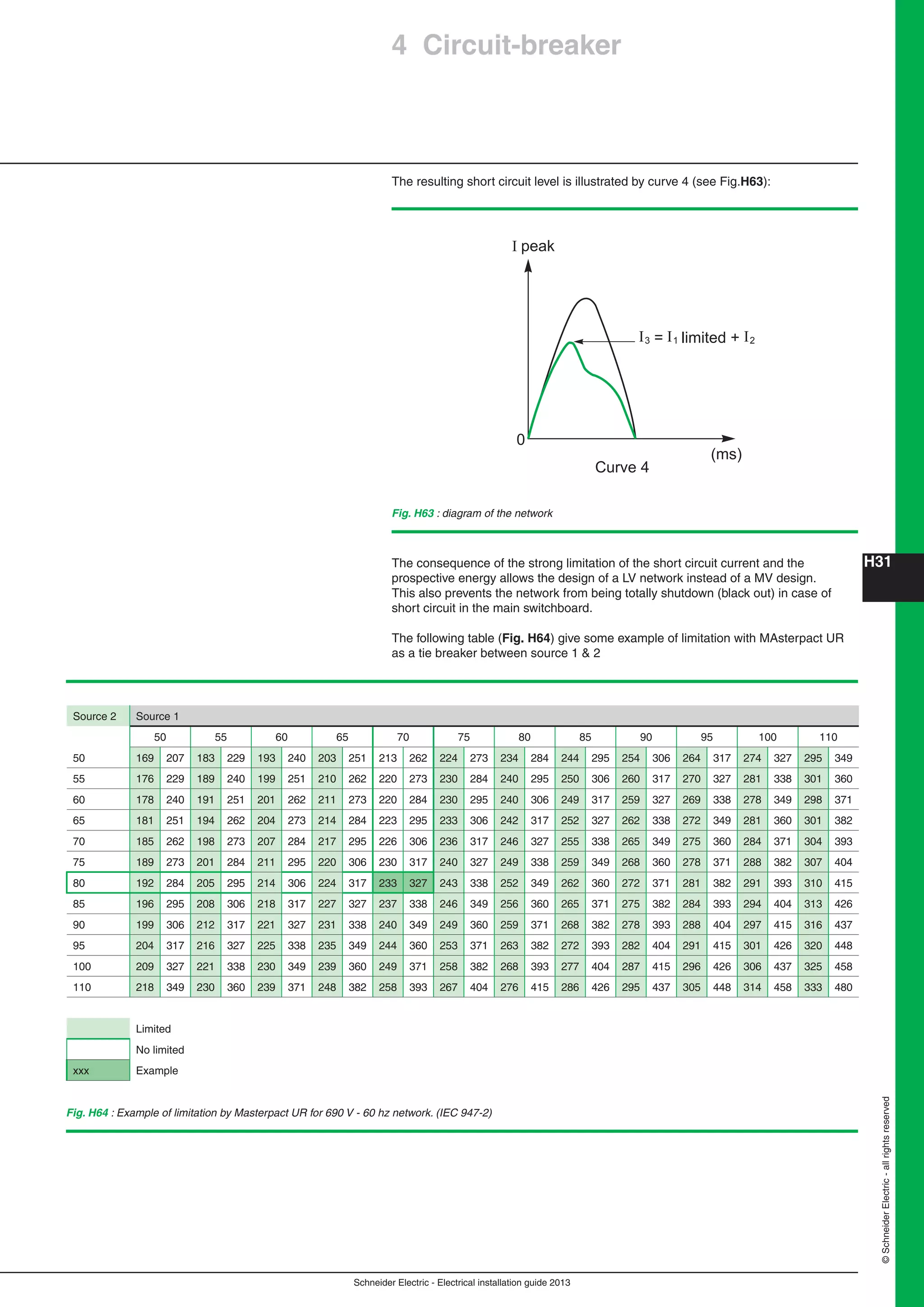
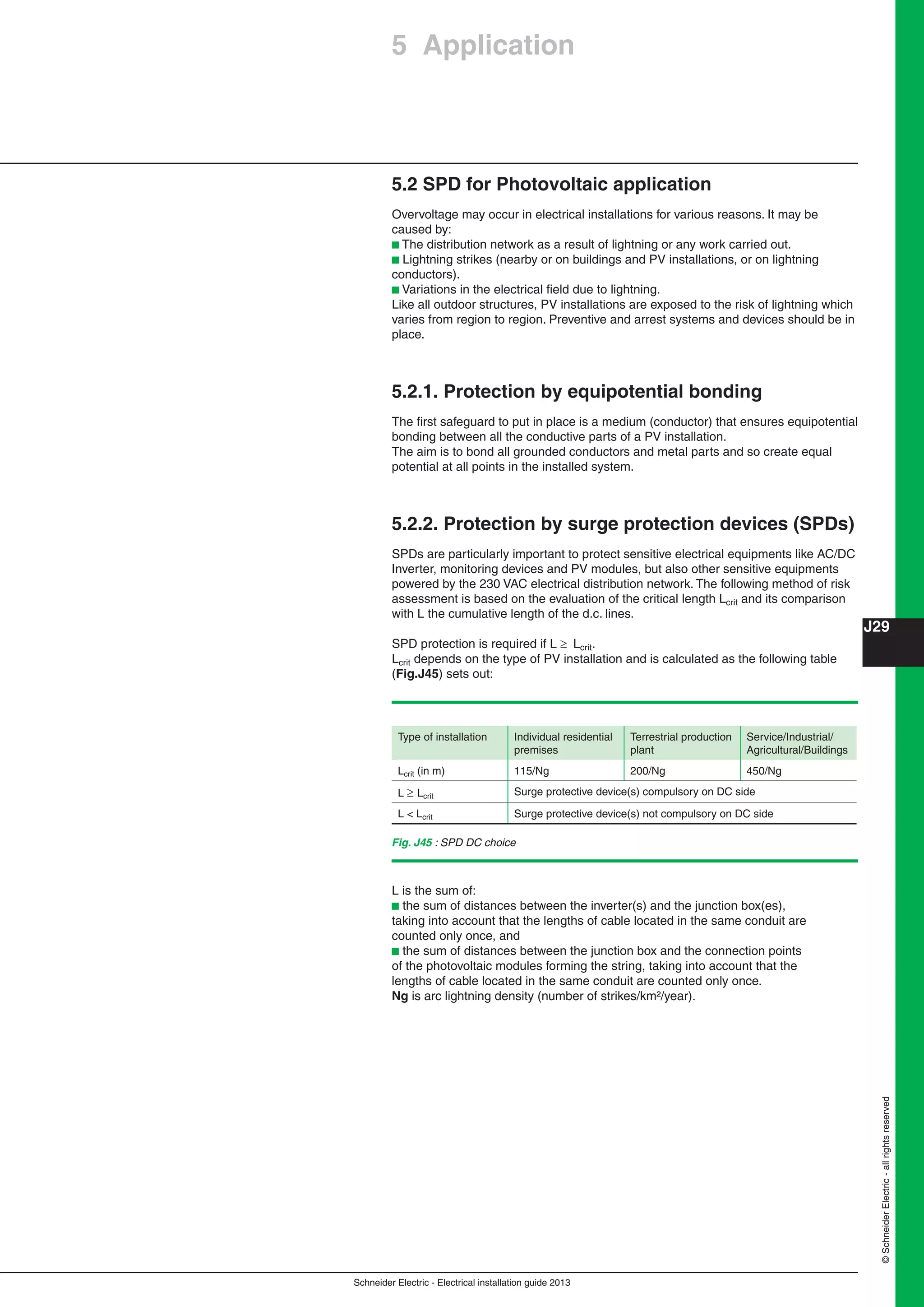
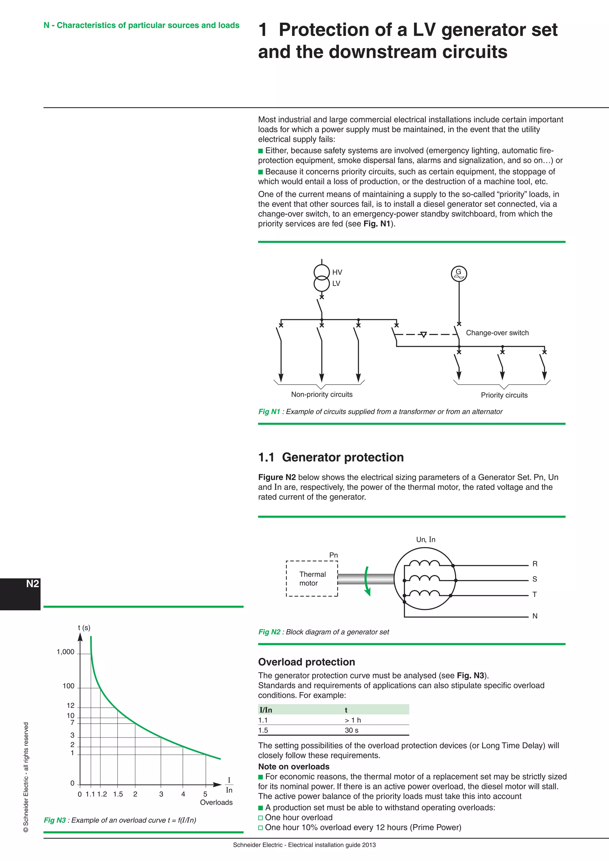
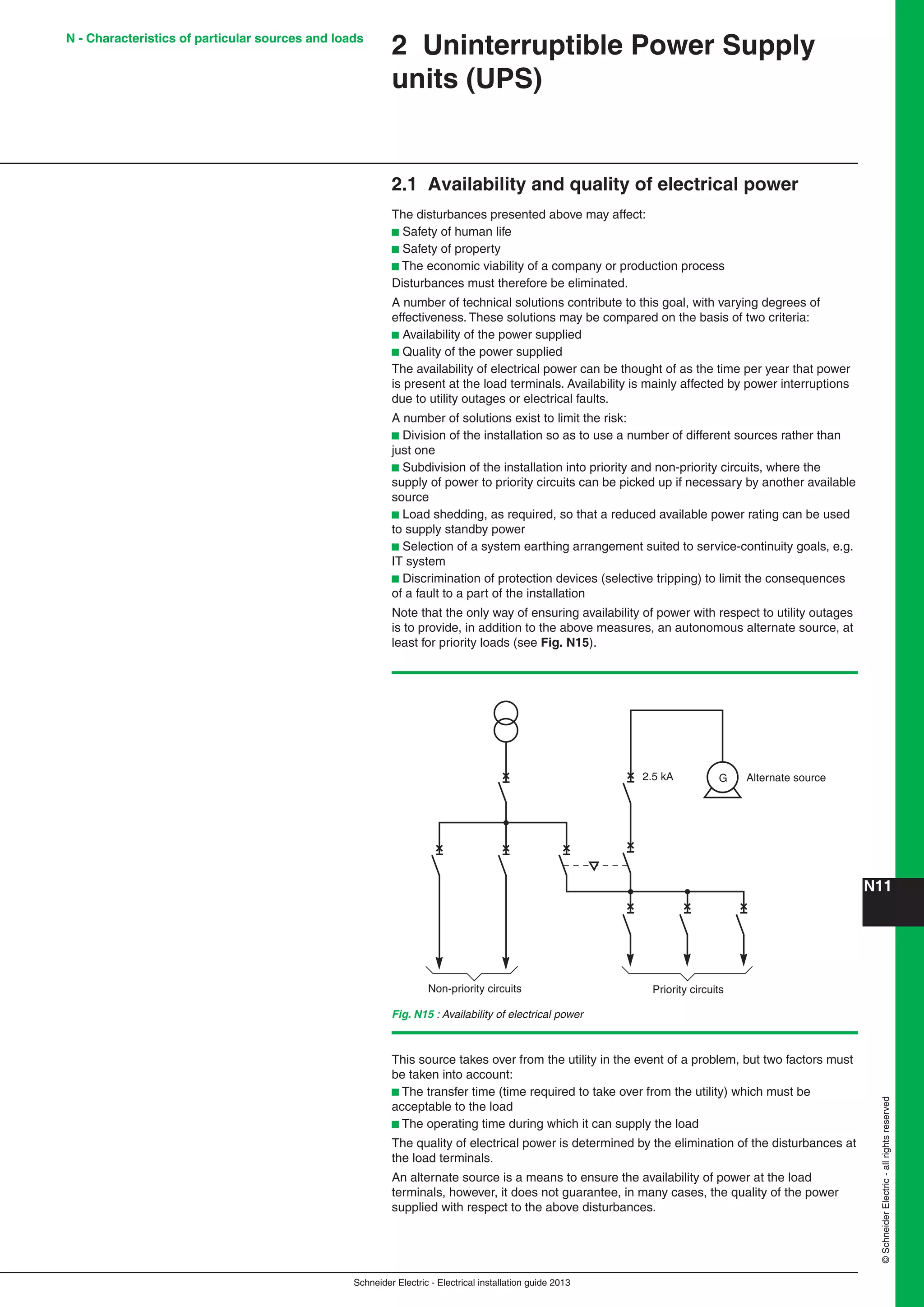
Selection tables
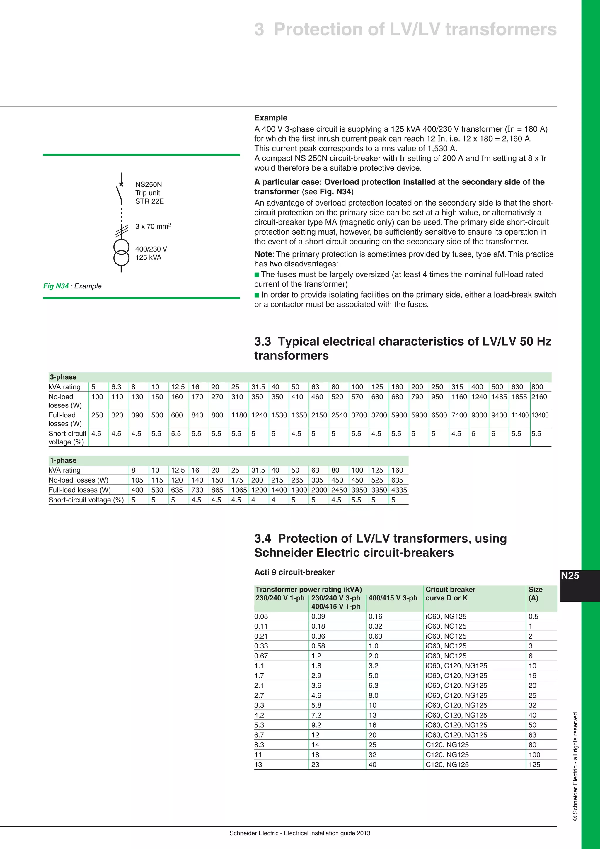
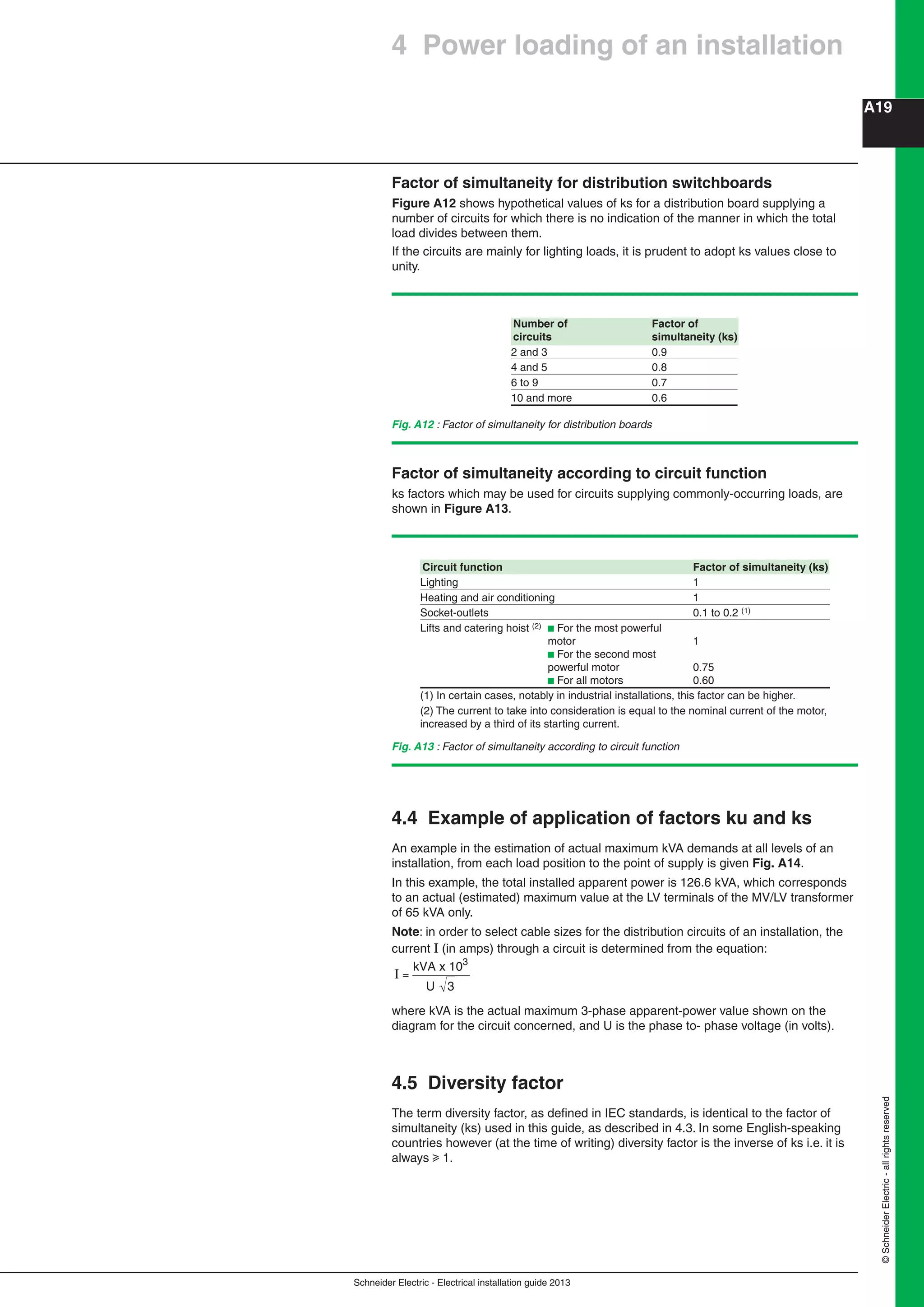
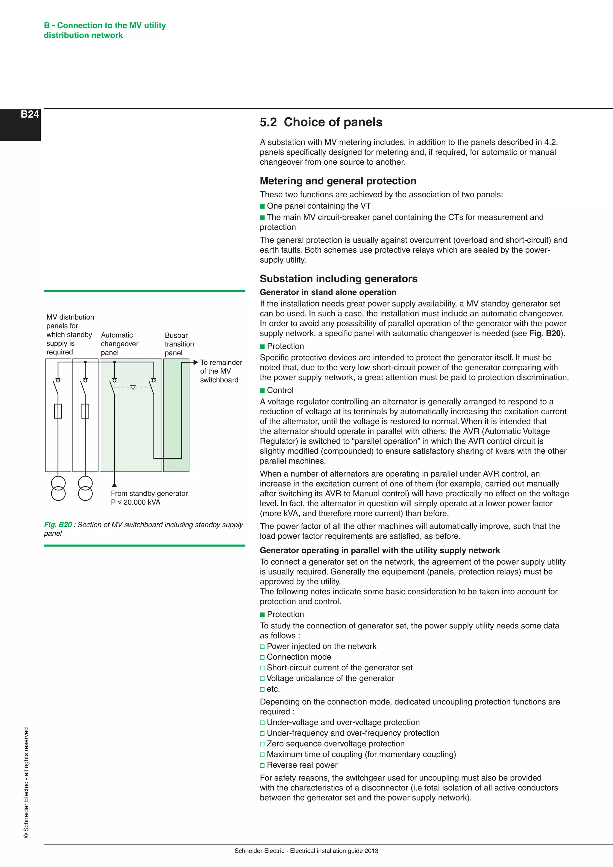
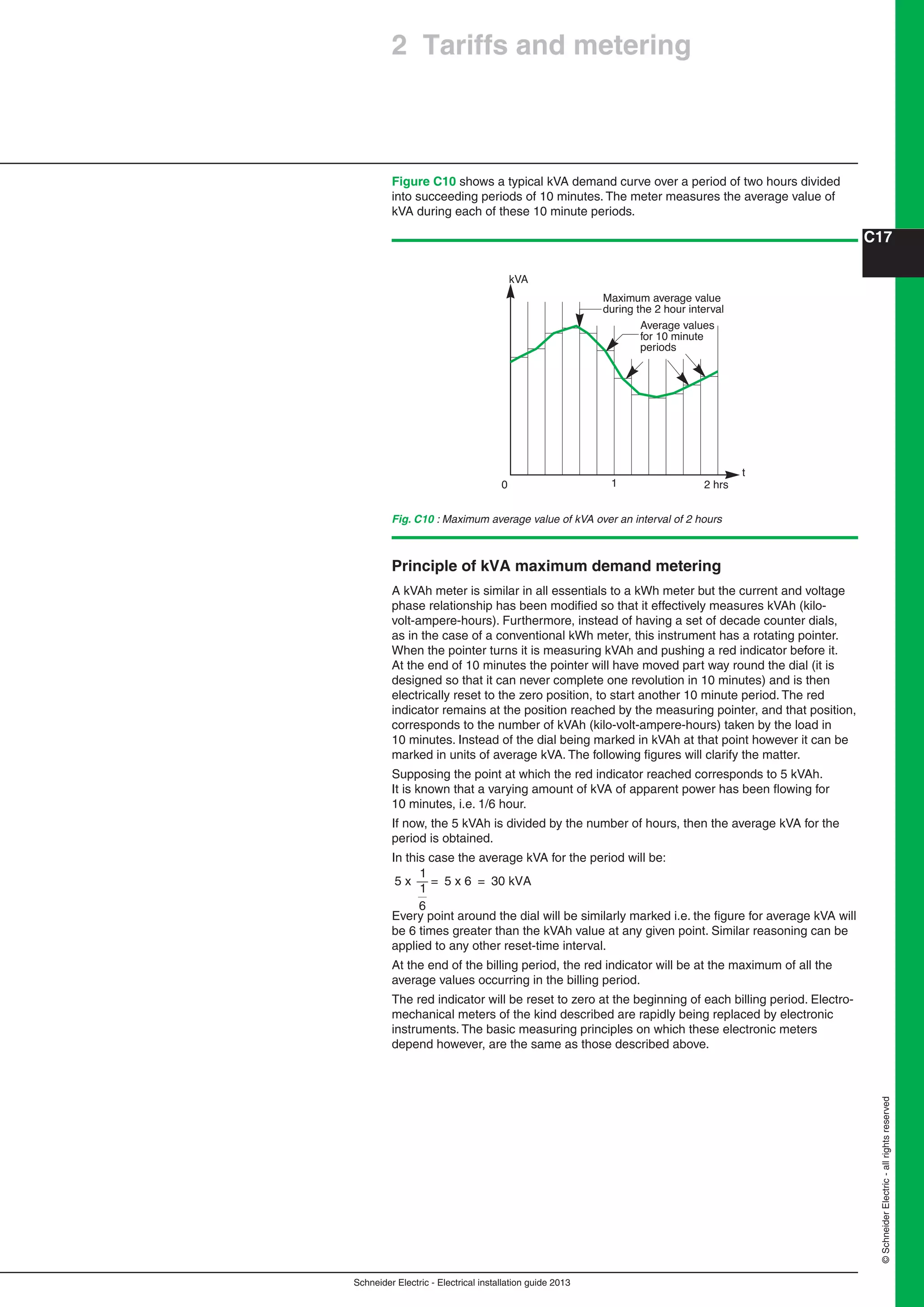
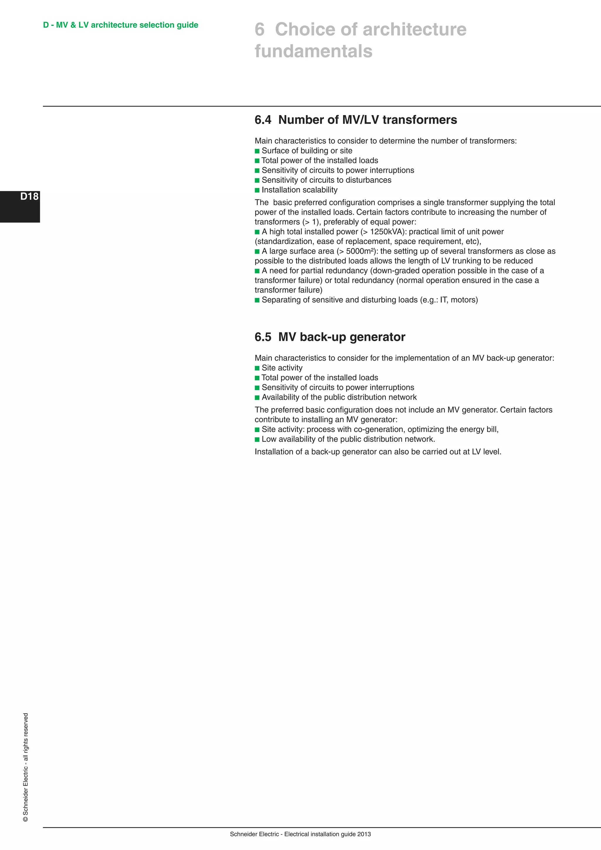
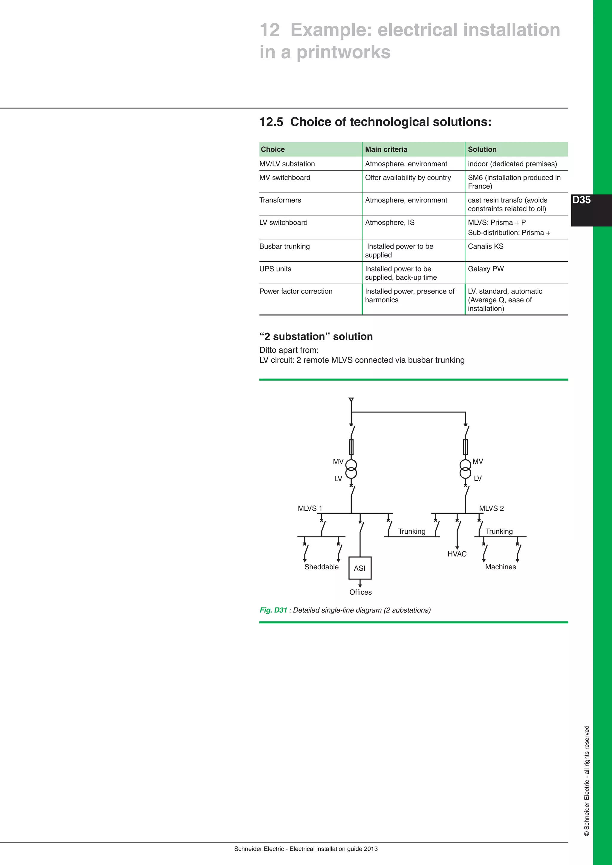
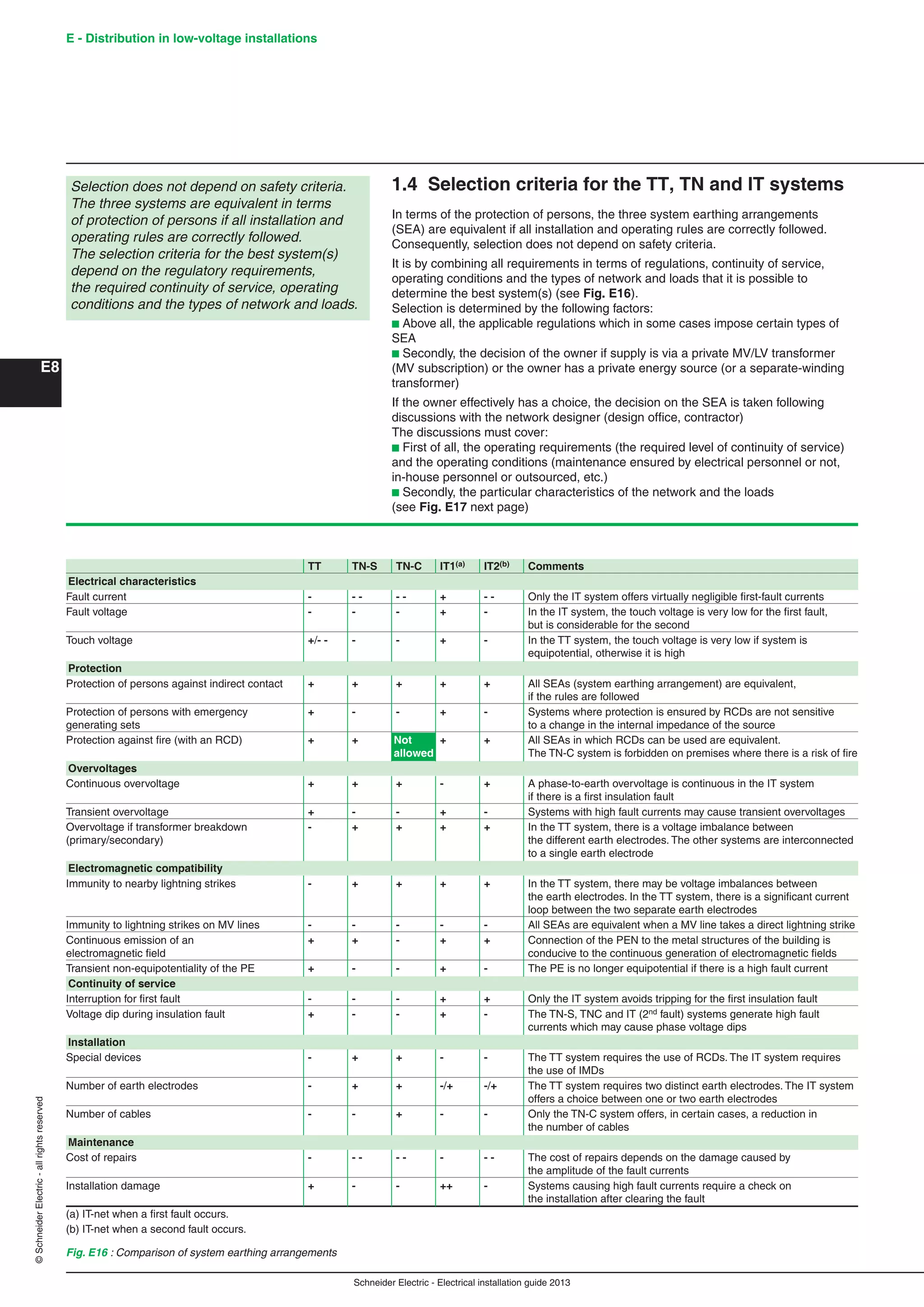
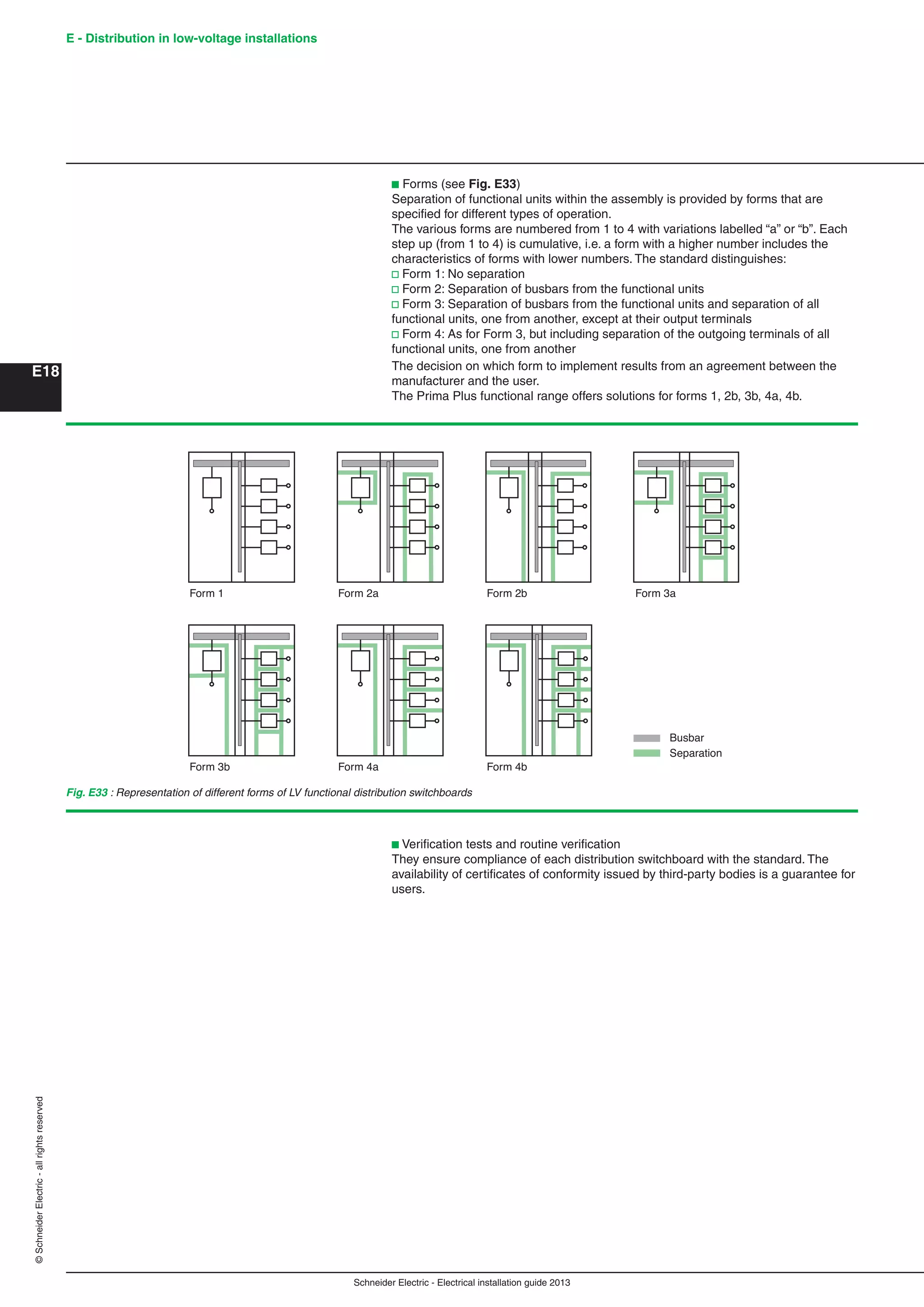
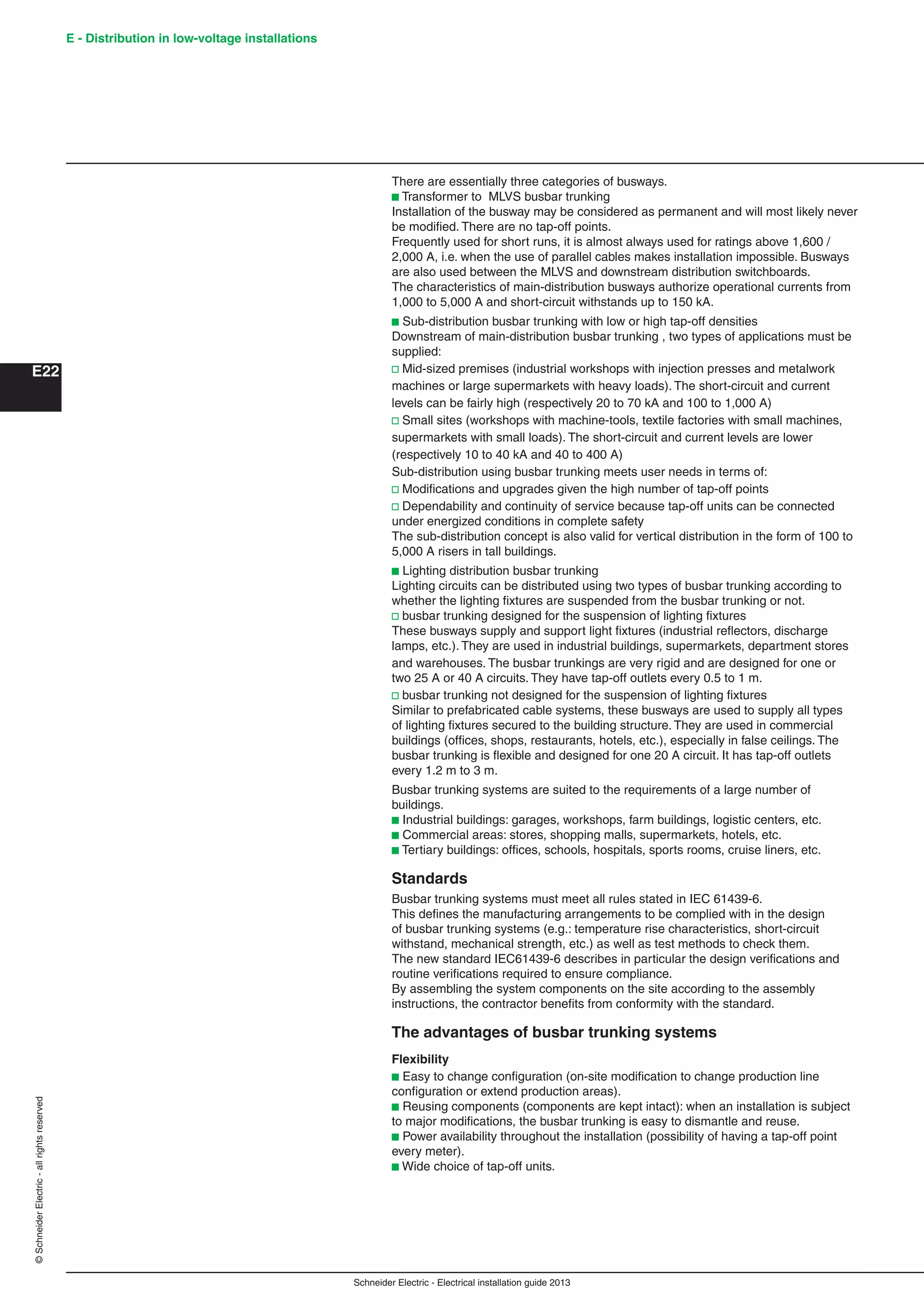
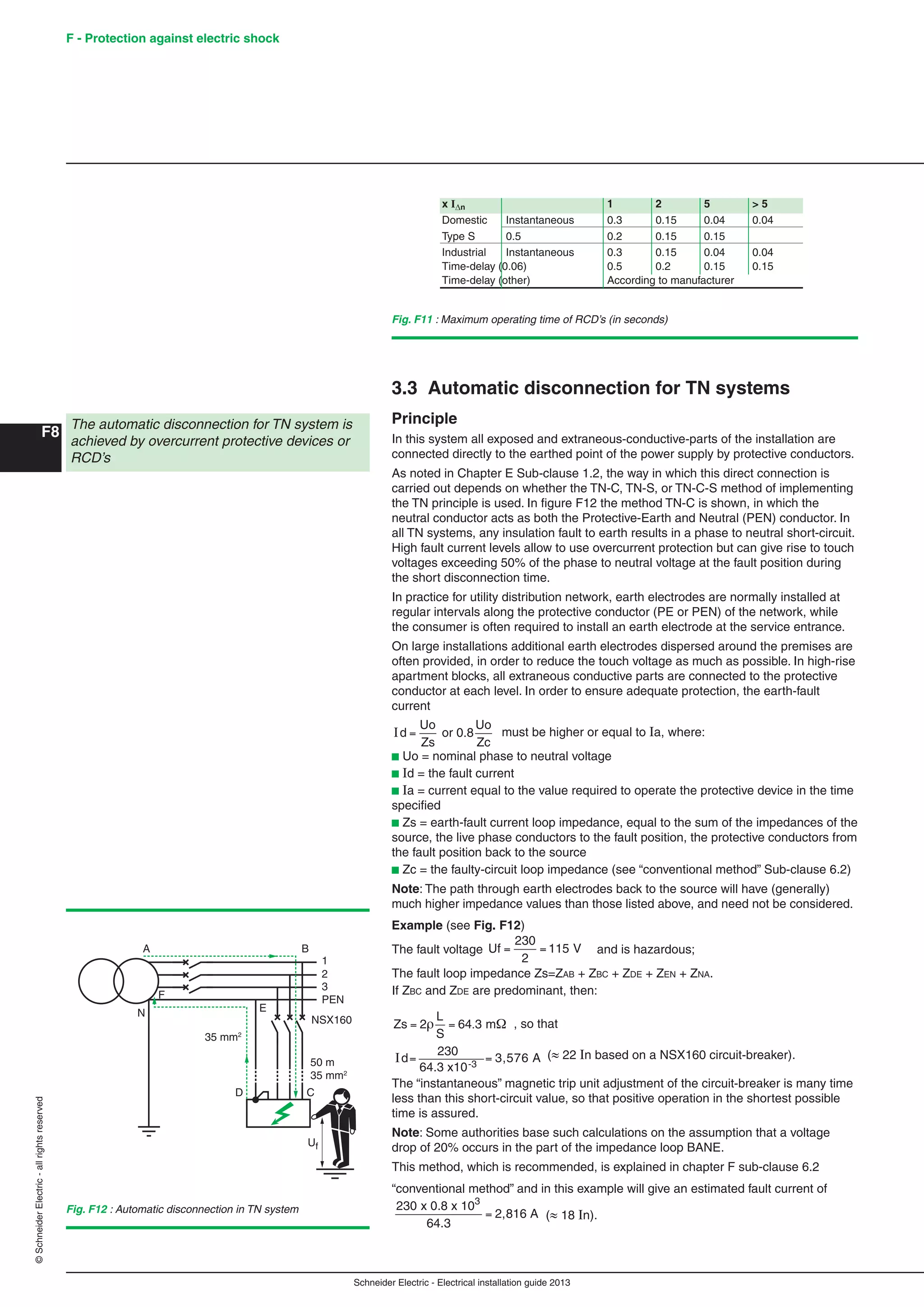
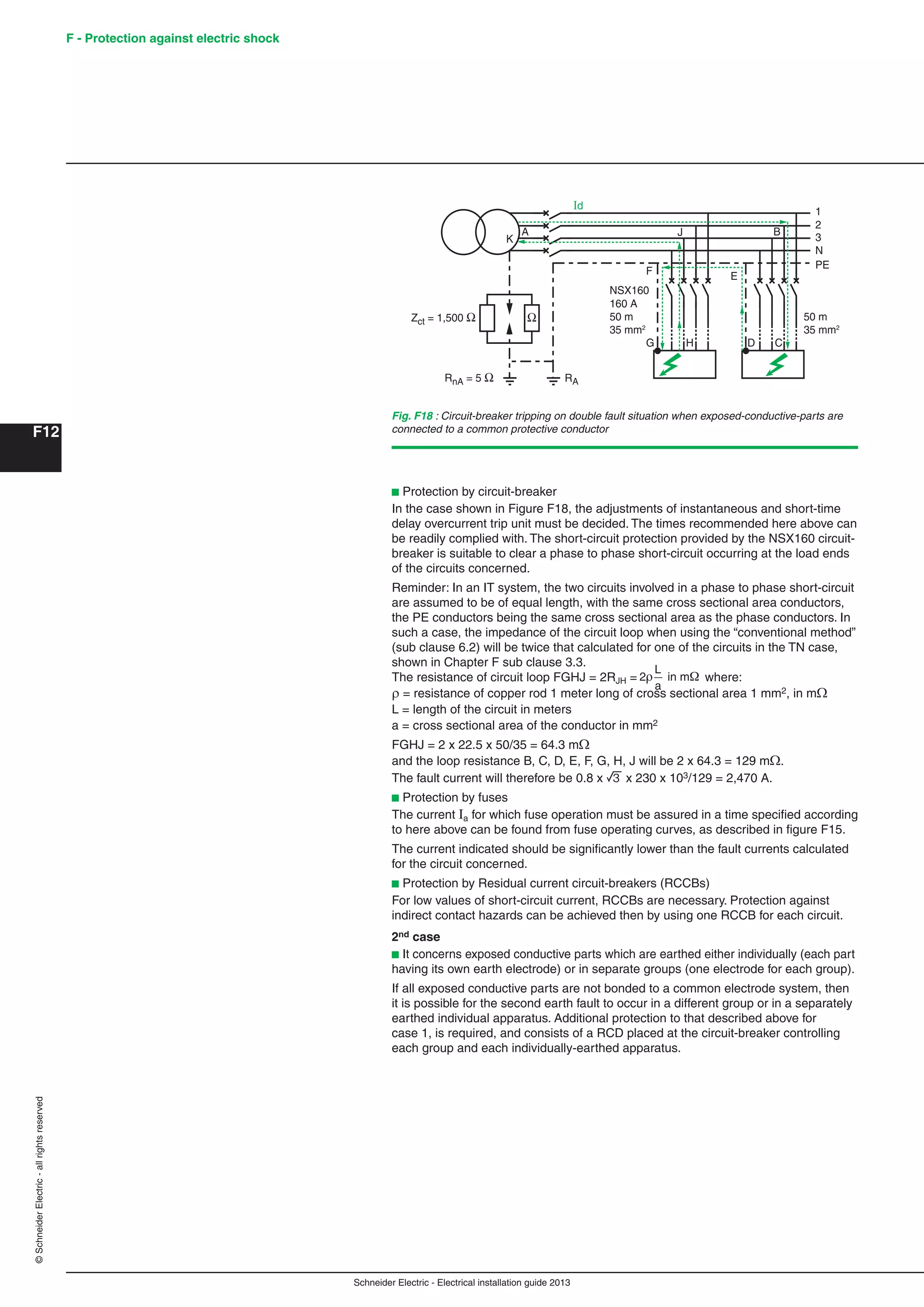
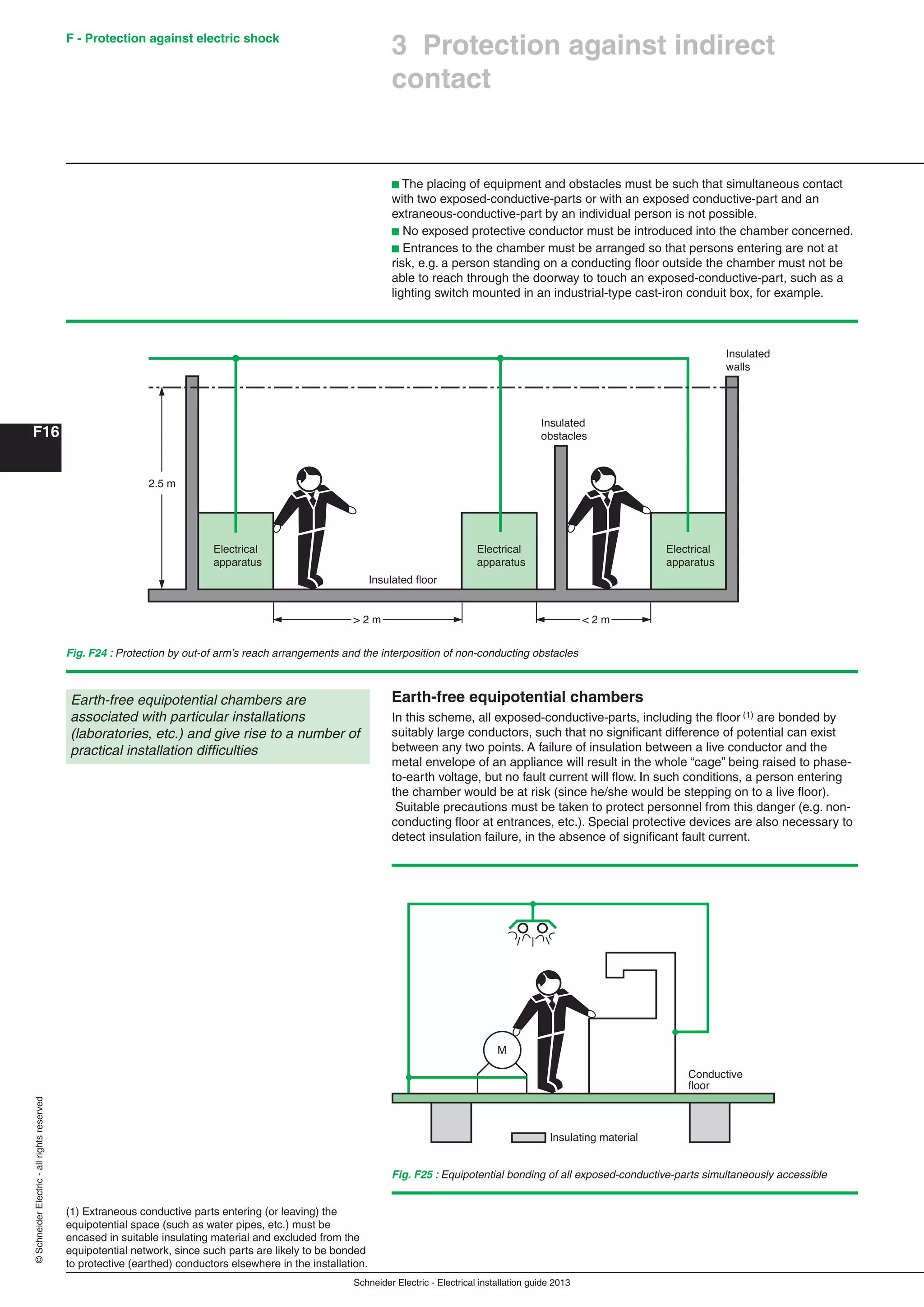
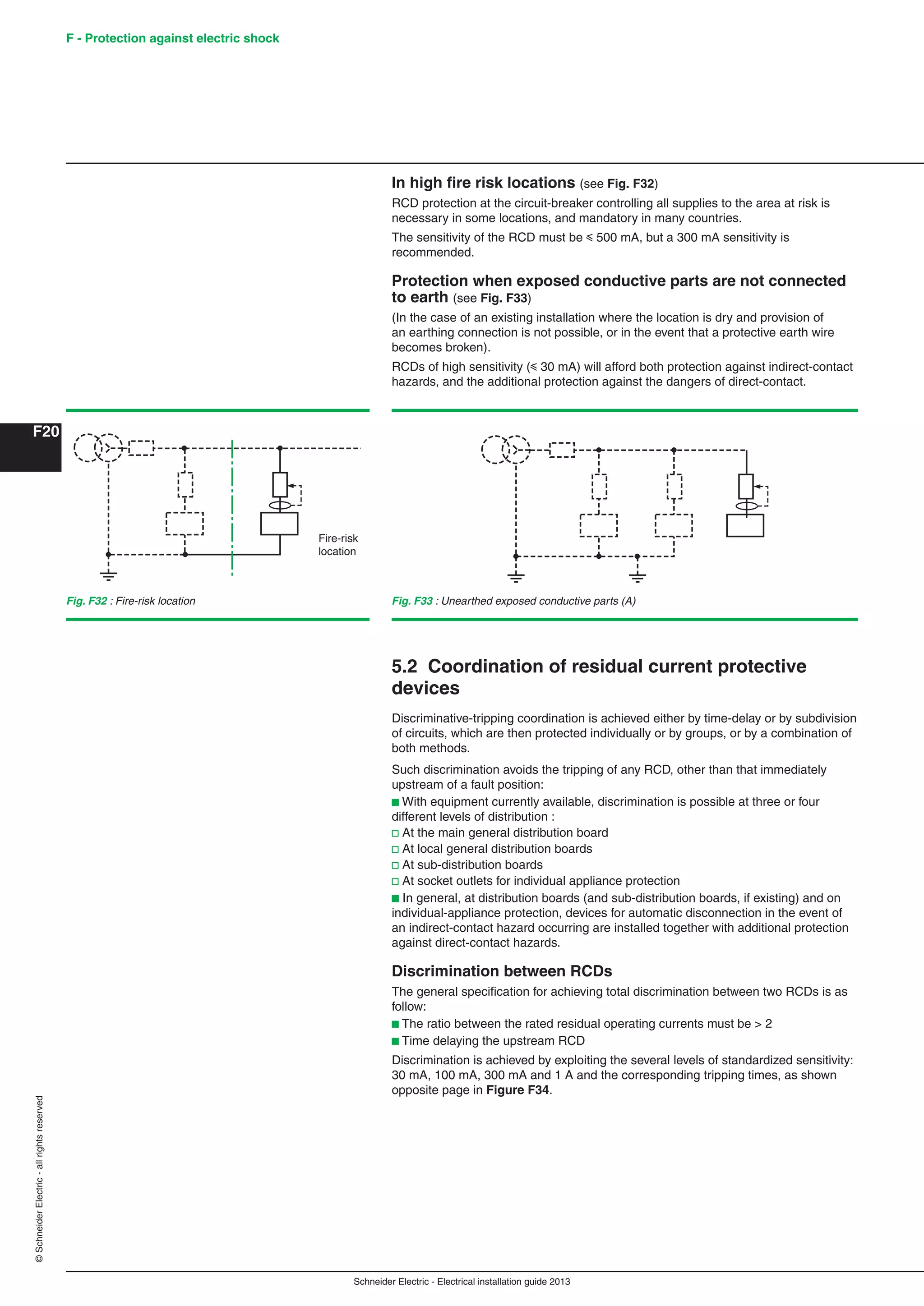
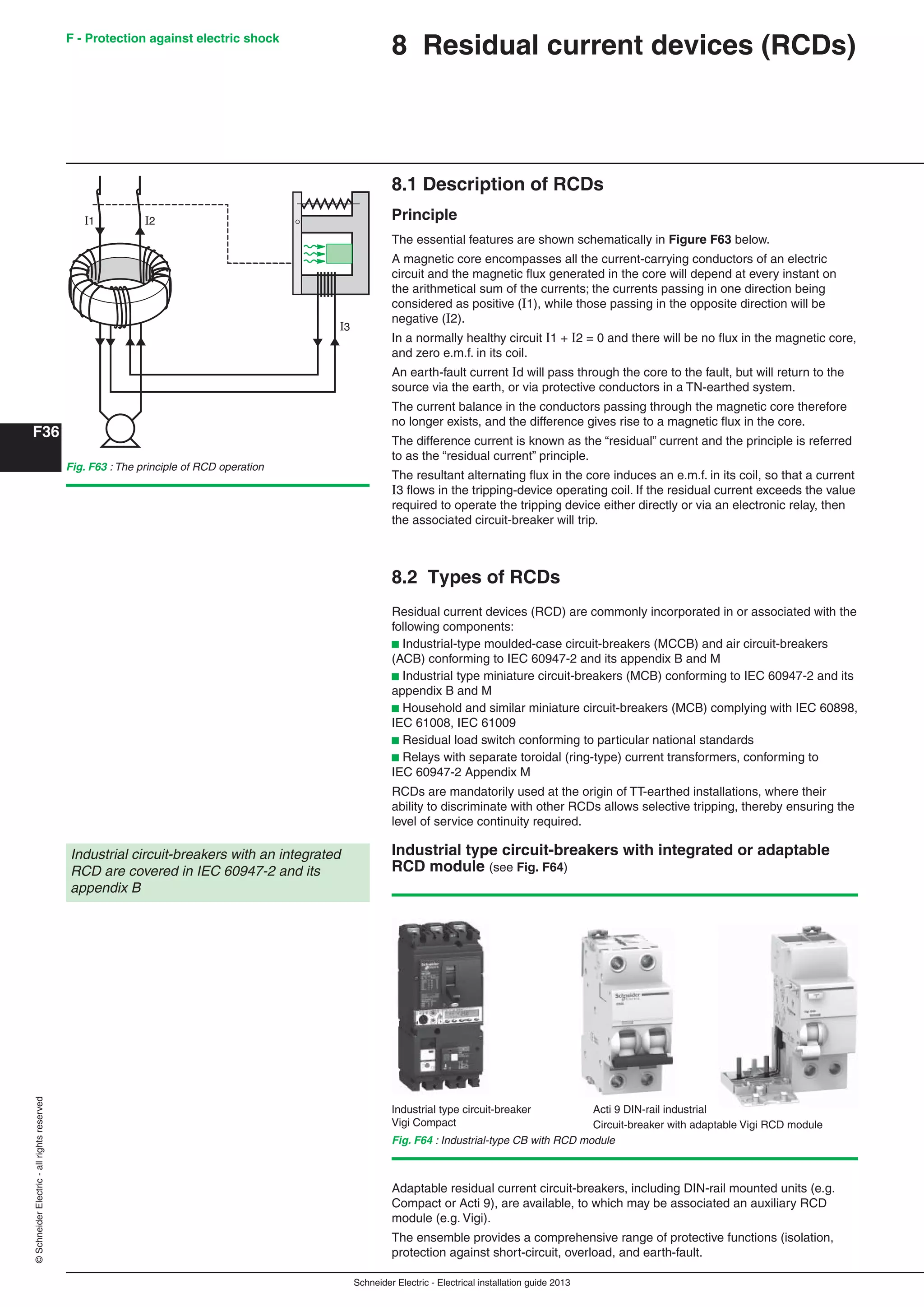
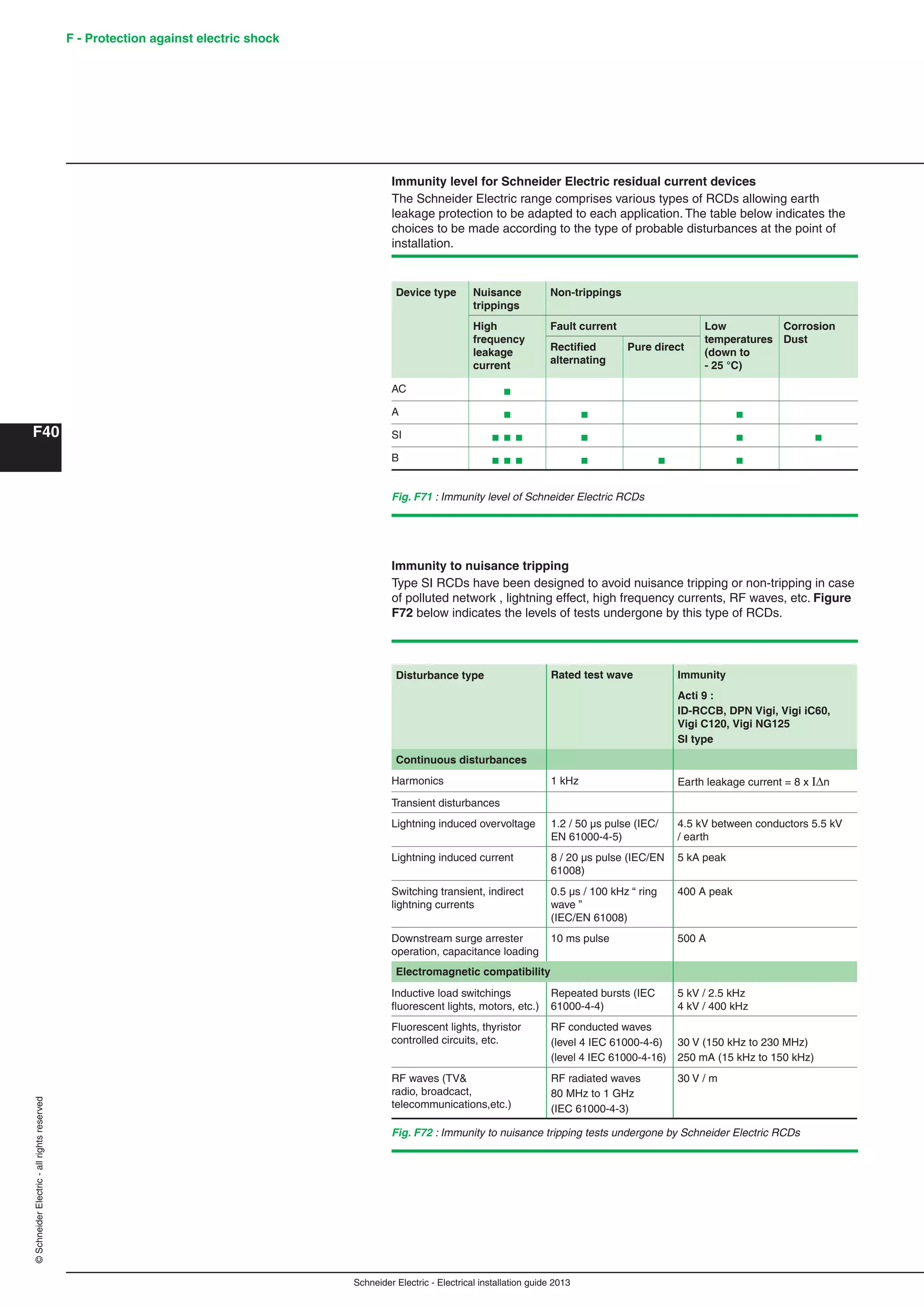
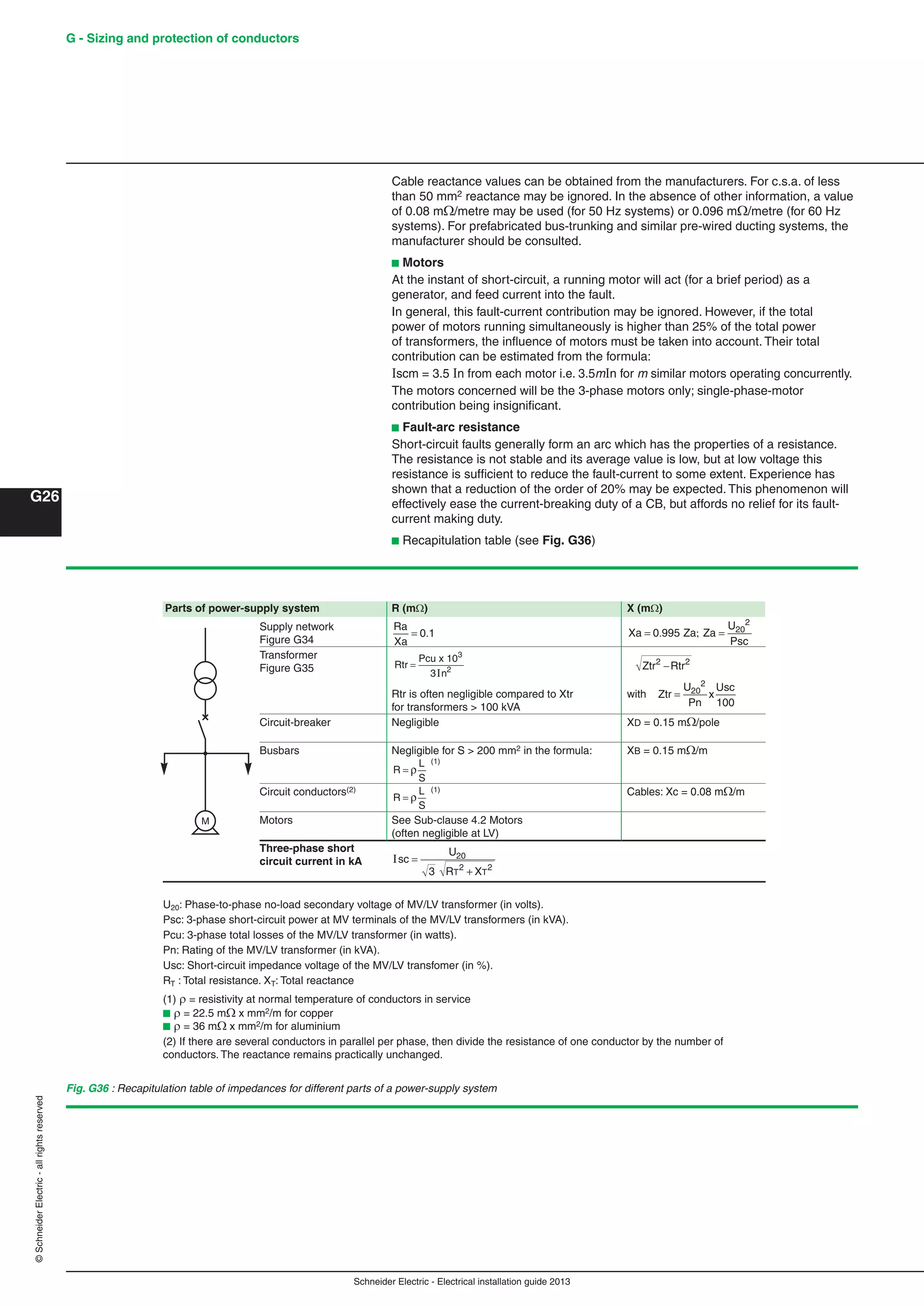
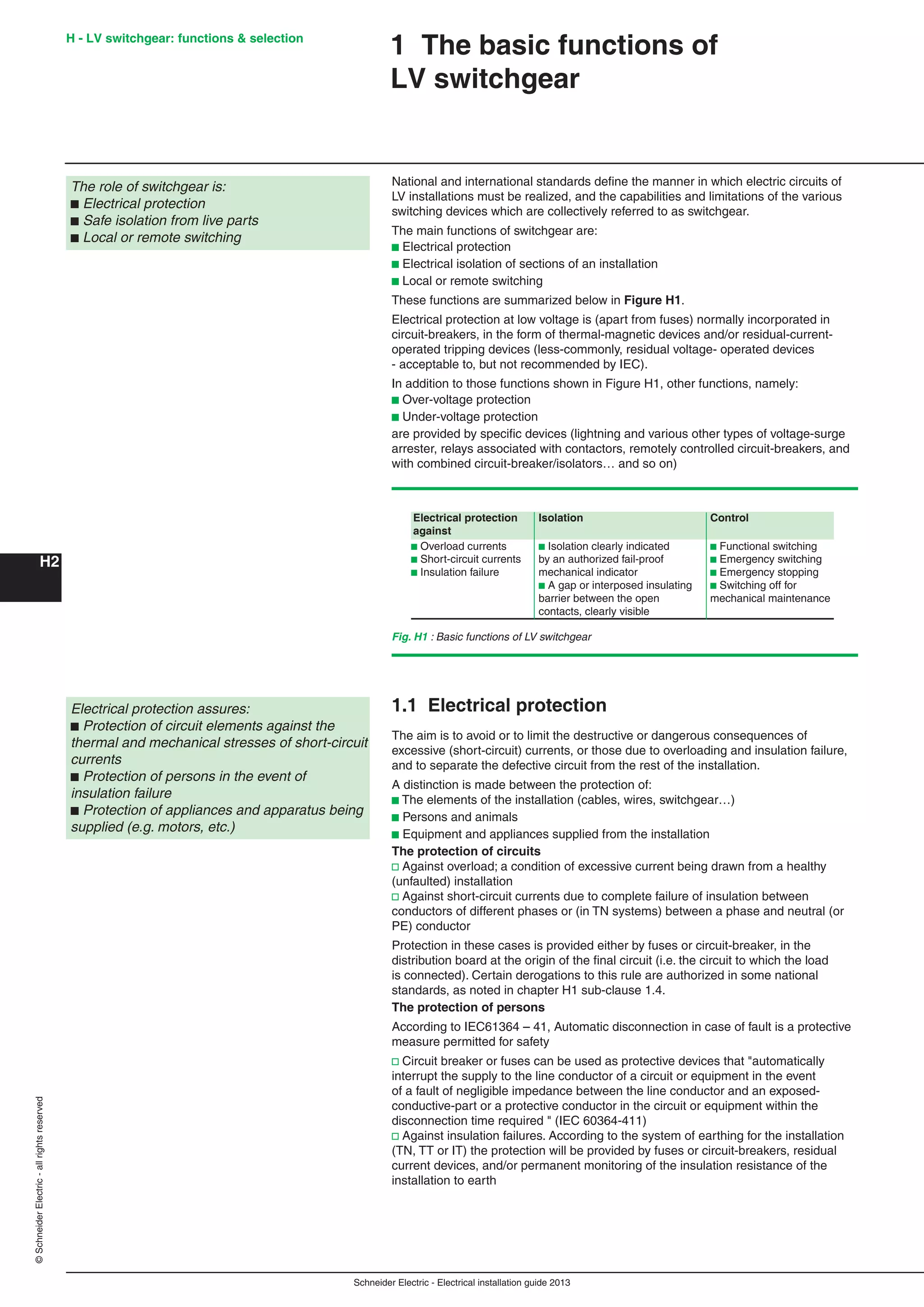
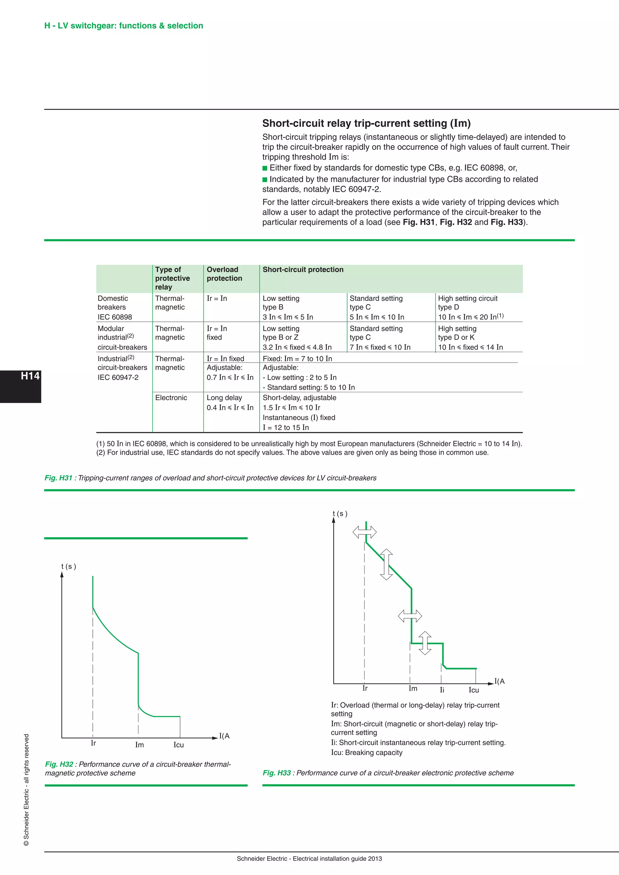
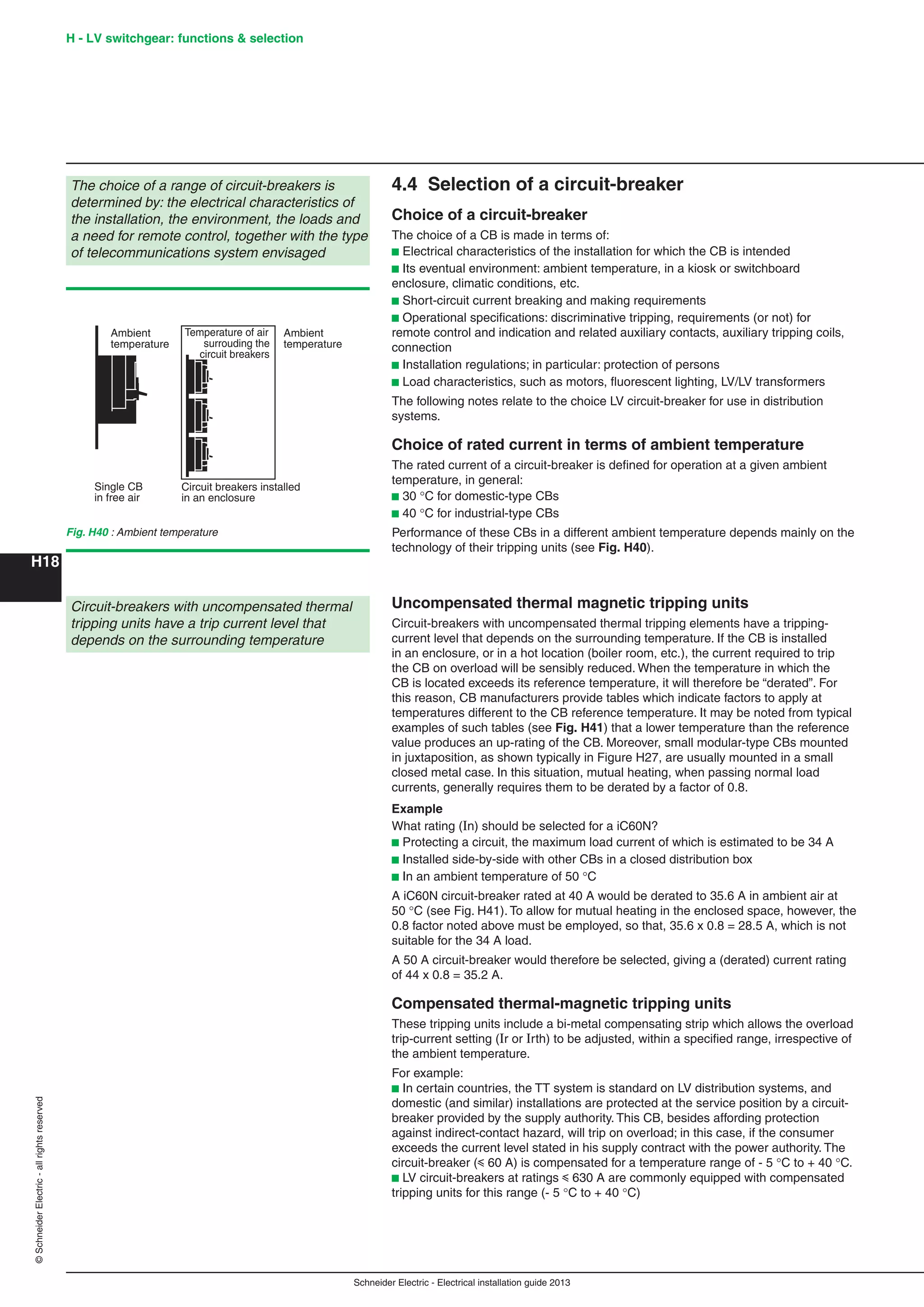
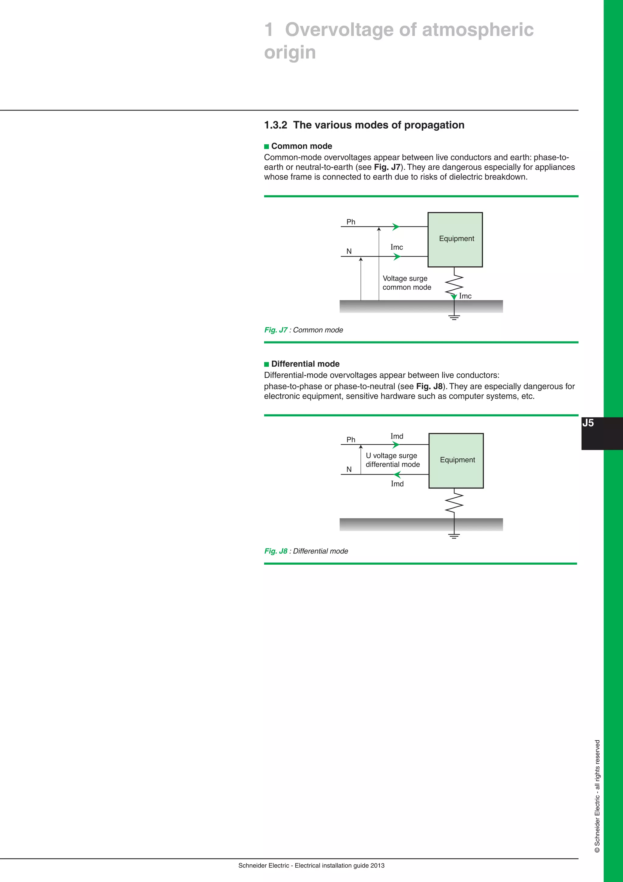
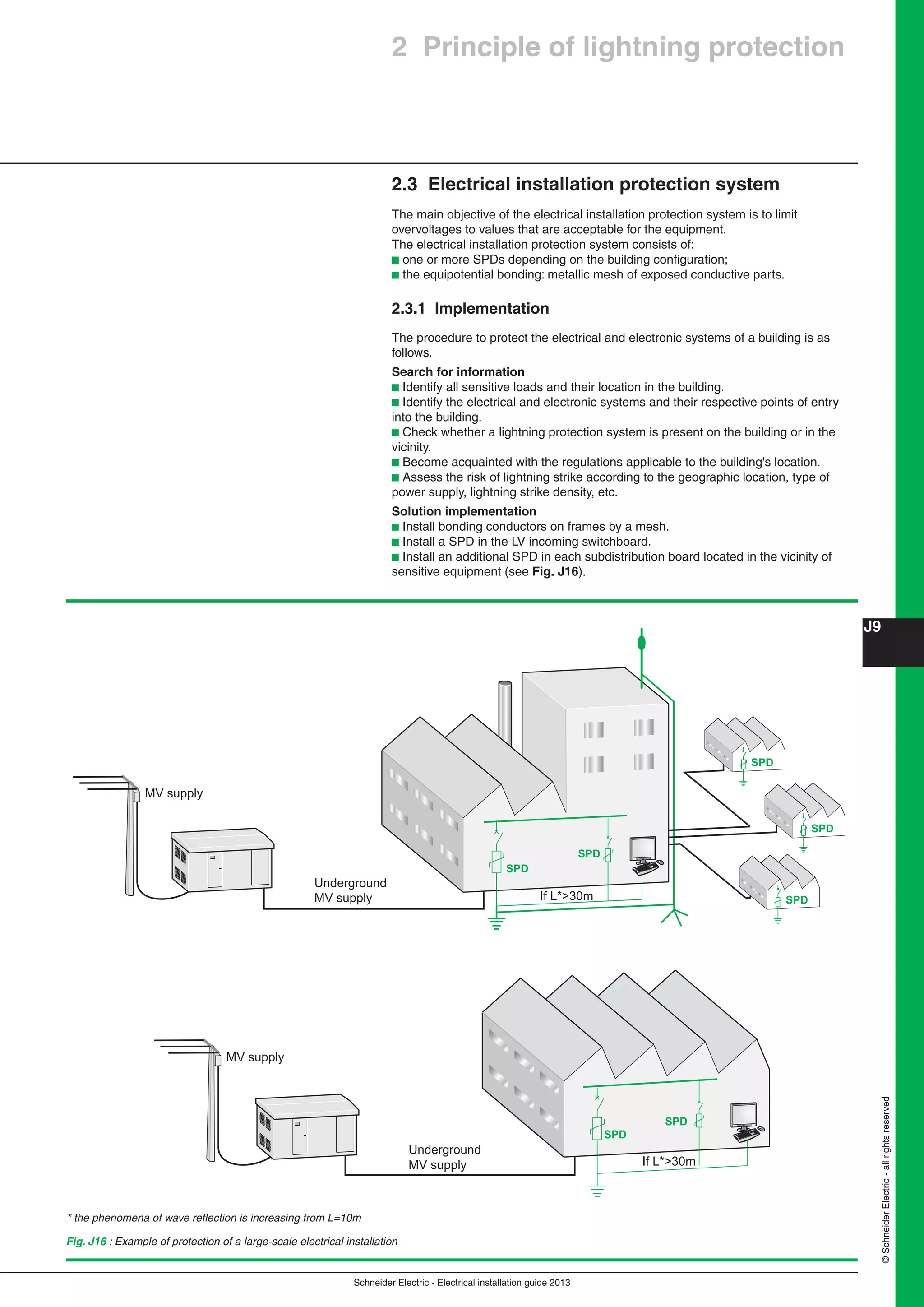
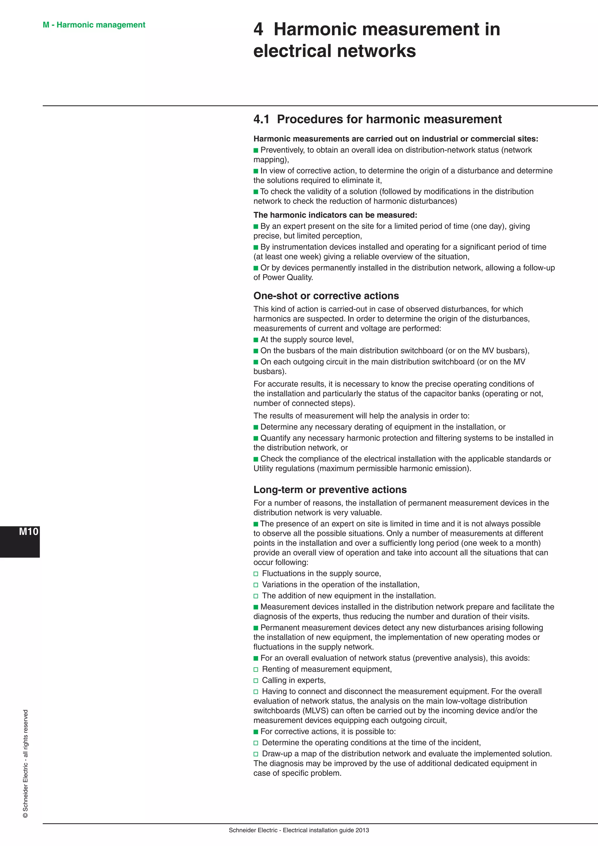
Figure N29 indicates the voltage drop in percent for a circuit made up of 100 meters
of cable. To calculate the voltage drop in a circuit with a length L, multiply the value in
the table by L/100.
b Sph: Cross section of conductors
b In: Rated current of protection devices on circuit
Three-phase circuit
If the voltage drop exceeds 3% (50-60 Hz), increase the cross section of conductors.
DC circuit
If the voltage drop exceeds 1%, increase the cross section of conductors.
a - Three-phase circuits (copper conductors)
50-60 Hz - 380 V / 400 V / 415 V three-phase, cos = 0.8, balanced system three-phase + N
In Sph (mN2)
(A) 10 16 25 35 50 70 95 120 150 185 240 300
10 0.9
15 1.2
20 1.6 1.1
25 2.0 1.3 0.9
32 2.6 1.7 1.1
40 3.3 2.1 1.4 1.0
50 4.1 2.6 1.7 1.3 1.0
63 5.1 3.3 2.2 1.6 1.2 0.9
70 5.7 3.7 2.4 1.7 1.3 1.0 0.8
80 6.5 4.2 2.7 2.1 1.5 1.2 0.9 0.7
100 8.2 5.3 3.4 2.6 2.0 2.0 1.1 0.9 0.8
125 6.6 4.3 3.2 2.4 2.4 1.4 1.1 1.0 0.8
160 5.5 4.3 3.2 3.2 1.8 1.5 1.2 1.1 0.9
200 5.3 3.9 3.9 2.2 1.8 1.6 1.3 1.2 0.9
250 4.9 4.9 2.8 2.3 1.9 1.7 1.4 1.2
320 3.5 2.9 2.5 2.1 1.9 1.5
400 4.4 3.6 3.1 2.7 2.3 1.9
500 4.5 3.9 3.4 2.9 2.4
600 4.9 4.2 3.6 3.0
800 5.3 4.4 3.8
1,000 6.5 4.7
For a three-phase 230 V circuit, multiply the result by e
For a single-phase 208/230 V circuit, multiply the result by 2
b - DC circuits (copper conductors)
In Sph (mN2)
(A) - - 25 35 50 70 95 120 150 185 240 300
100 5.1 3.6 2.6 1.9 1.3 1.0 0.8 0.7 0.5 0.4
125 4.5 3.2 2.3 1.6 1.3 1.0 0.8 0.6 0.5
160 4.0 2.9 2.2 1.6 1.2 1.1 0.6 0.7
200 3.6 2.7 2.2 1.6 1.3 1.0 0.8
250 3.3 2.7 2.2 1.7 1.3 1.0
320 3.4 2.7 2.1 1.6 1.3
400 3.4 2.8 2.1 1.6
500 3.4 2.6 2.1
600 4.3 3.3 2.7
800 4.2 3.4
1,000 5.3 4.2
1,250 5.3
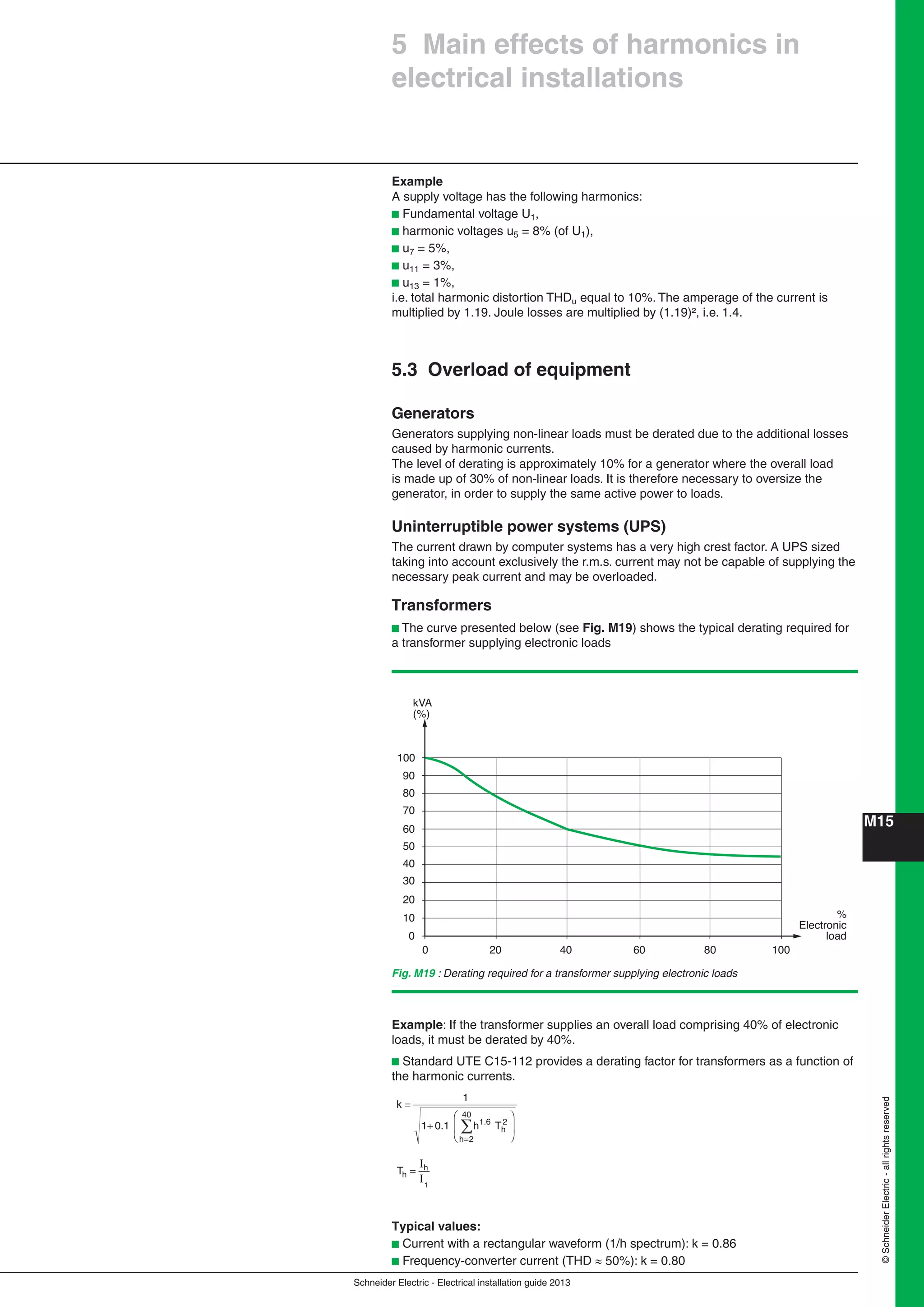
Fig. N29 : Voltage drop in percent for [a] three-phase circuits and [b] DC circuits
Special case for neutral conductors
In three-phase systems, the third-order harmonics (and their multiples) of single-
phase loads add up in the neutral conductor (sum of the currents on the three
phases).
For this reason, the following rule may be applied:
neutral cross section = 1.5 x phase cross section](https://image.slidesharecdn.com/manualinstalacioneselectricas-150309124103-conversion-gate01/75/Manual-instalaciones-electricas-411-2048.jpg)