Downloaded 500 times
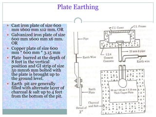
![Pipe Earthing
GI pipe [C-class] of
75 mm diameter
10 feet long welded
with welded flat
having 4 numbers of
holes for connections
Earth pits are
generally filled with
alternate layer of
charcoal & salt or
earth reactivation
compound.](https://image.slidesharecdn.com/earthinginelectricalnetwork-130426195622-phpapp02/85/Earthing-in-electrical-network-7-320.jpg)
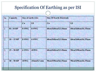
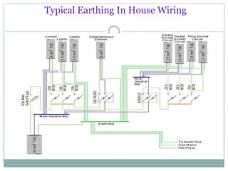


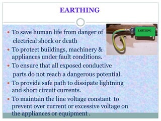
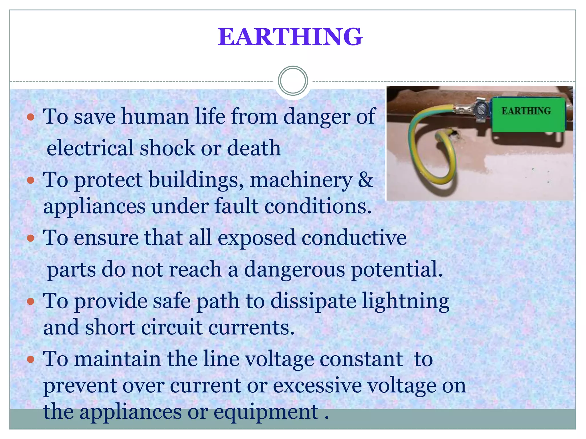
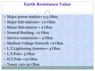
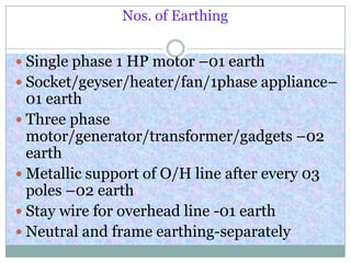
This document provides information about earthing systems including their purposes, specifications, types, and maintenance. The key points are: 1) Earthing systems are used to protect lives and equipment from electrical shock by providing a safe path for currents to travel and ensuring conductive parts do not reach dangerous potentials. 2) Recommended earth resistance values vary based on the equipment, with substations requiring lower values like 0.5-2 ohms and individual devices like poles needing 5-10 ohms. 3) Common earthing types include pipe, plate, strip, and rod systems, with factors like soil conditions determining which type is best. Pipe earthing using galvanized iron pipes 10 feet long is very


