Download to read offline
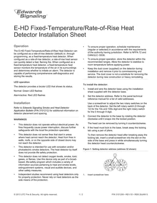

The e-hd fixed-temperature/rate-of-rise heat detector can function as either a rate-of-rise detector or a fixed-temperature heat detector, allowing for quick detection of fires or temperature monitoring. It features comprehensive self-diagnostics, a bicolor LED status indicator, and must be used alongside additional safety measures for property protection. Installation instructions and safety warnings emphasize the importance of proper maintenance and adherence to relevant standards.


![5G Explained! A High Level Overview [Introduction]](https://cdn.slidesharecdn.com/ss_thumbnails/5gexplainedahighleveloverview-260119165306-cc137a3e-thumbnail.jpg?width=640&height=640&fit=bounds)


