Download to read offline
![RSSP‑241575W‑FR Fixed‑candela retrofit strobe
plate
RSSP‑24MCW‑FR Multi‑candela retrofit strobe
plate
RSSP‑24MCWH‑FR High‑candela retrofit strobe
plate
1
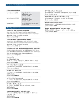
For synchronization, use the SM or DSM
Synchronization Modules. The synchronization module
must be set for 24 VDC operation. When used, the
D7022 must be set for 24 VDC operation.
2
When used with a D7039 Multiplex Expansion
Module, the FPD-7024 and D7024 become
addressable fire alarm control panels (FACPs).
Mounting Considerations
Use as Combination Appliance
Where combination appliances are required, the
AH‑24‑R Horn can be used with the RSSP‑241575W‑FR
Fixed‑candela, RSSP‑24MCW‑FR Multi‑candela, or
RSSP‑24MCWH‑FR High‑candela Retrofit Strobe Plates
that are designed to meet or exceed the latest
requirements of NFPA 72, ANSI 117.0 and UL 1971.
The horns and retrofit strobe plates are also
compatible with the SBL2‑R Retrofit Device Back Box.
Outdoor or Severe Environment Applications
For an outdoor application or a severe environment
(NEMA 3R) application, the AH‑24WP Weatherproof
Horn in combination with a WBB‑R Weatherproof Back
Box must be mounted on a flat wall such that the wall
covers the entire rear surface of the back box. The
back box must have its drain holes pointed toward the
ground. The knockouts in the rear surface of the back
box must remain intact.
The knockout hole on top of the back box is sized for a
half‑inch conduit and matching connector. A proper
watertight conduit fitting must be used.
Indoor Applications
The AH‑24‑R and AH‑24‑W Horns are equipped with a
mounting plate that mounts on the indicated back
boxes for the indicated applications:
Conduit
Applications
Surface
Mounted
Flush
Mounted
Single‑gang •
Double‑gang • •
Four‑inch square • •
100‑mm European • •
SHBB-R • •
The AH‑24WP Weatherproof Horn can be indoor
surface‑mounted on a deep (>2.125 in. [5.4 cm]), four-
inch square back box.
Wiring
Notice
Do not use these horns in coded systems in which
the voltage is cycled on and off.
The input terminals accept wires with diameters
between 18 AWG and 12 AWG (ISO 0.75 mm2
and
4 mm2
).
Parts included
Quant. Component
1 Horn
1 Mounting Plate
1 Hardware pack
1 Literature pack
Technical specifications
Environmental Considerations
Relative Humidity: Up to 95%, non‑condensing
Temperature (operating): +32°F to +120°F (0°C to +49°C)
Horn Ratings at 24 VDC
Continuous Horn
Reverberant dBA at 10 ft (3 m) per
UL464:
High: 91 dBA
Medium: 88 dBA
Low: 83 dBA
Temporal (Code 3) Horn
Reverberant dBA at 10 ft (3 m) per
UL464:
High: 87 dBA
Medium: 84 dBA
Low: 79 dBA
Notice
The sound output for the Temporal (Code 3)
mode is rated lower than in Continuous mode
because the time that the horn is off is averaged
into the sound output rating. When the horn
produces a tone in Temporal mode, its sound
pressure is the same as the Continuous mode.
Mechanical Properties
Dimensions (H x W x D): 4.125 in. x 4.125 in. x 1.25 in.
(10.5 cm x 10.5 cm x 3.2 cm)
Material: Molded plastic enclosure
2 | AH‑24 24 V Electronic Horns](https://image.slidesharecdn.com/ah-24wp-r-151223174512/85/Bosch-AH-24WP-R-Data-Sheet-2-320.jpg)

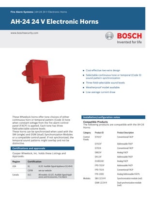
The document details the specifications and features of Bosch's AH-24 24V electronic horns, highlighting their cost-effective design, selectable sound patterns, and synchronization capabilities. It includes information on certifications, compatible products, environmental considerations, and technical specifications such as sound levels and mounting options. Additionally, ordering information for the horns and various accessories is provided.


