Downloaded 19 times


![180 E3 Series Installation/Operation Manual — P/N 9000-0574:L1 03/14/12
E3 Series System Connections Digital Alarm Communicator Transmitter (DACT-E3) Connections
3.10.5 DACT-E3 Contact ID Event Reporting Codes in CAMWorks
In the CAMWorks program, there are two (2) types of formats used to configure the DACT-E3
Contact ID Event Reporting Codes.
• Standard Format
• Custom Format
3.10.5.1 Standard Formats
The DACT-E3 can be configured to allow each SLC device to report an event by selecting the
DACT Reporting Feature. To define the Standard format for the ILI-E3/ILI95-E3 Series panel,
enable the Standard Reporting Codes in the DACT Report Format Section of the DACT Settings
screen in CAMWorks. The Custom DACT Reporting Feature is usually disabled by default. If you
disable the Custom DACT Reporting Feature, the system uses the Standard Codes. For
information on the DACT-E3 Contact ID Event Reporting Codes for Standard Formats, refer to
Table 3.10.5.1.1.
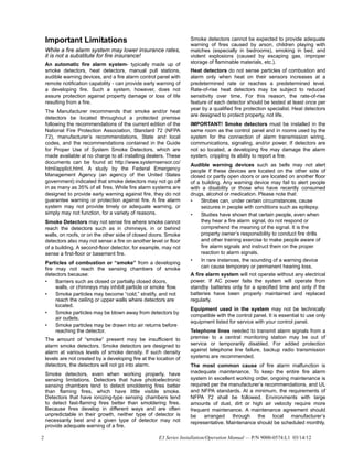
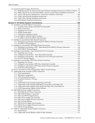
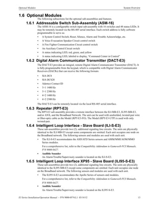
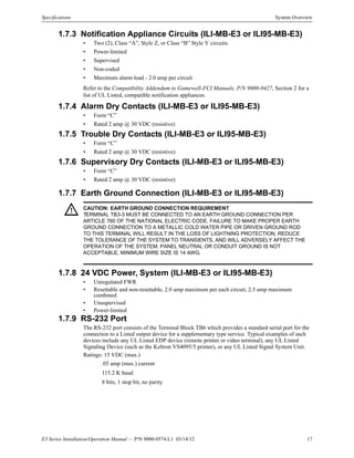
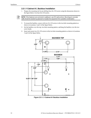
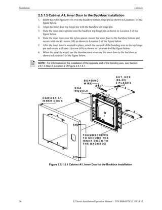
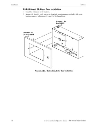
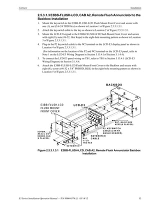
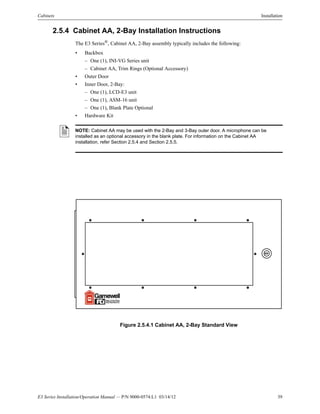
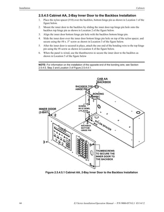
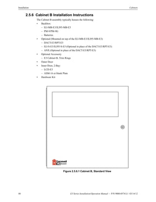
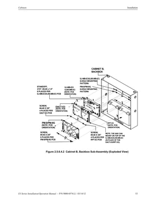
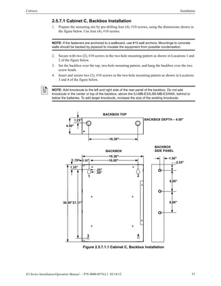
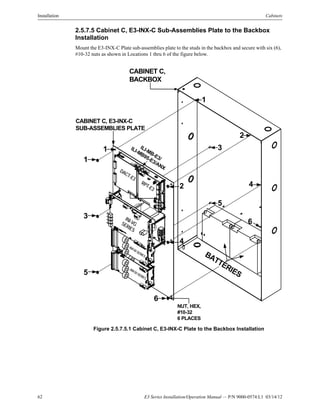
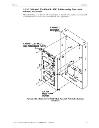
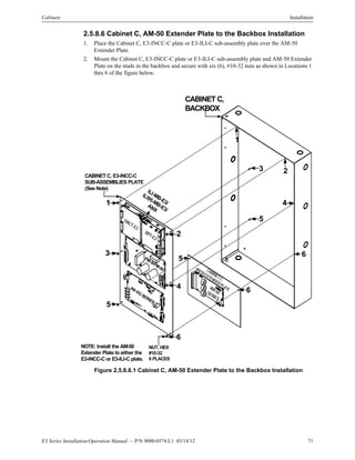
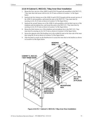
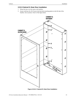
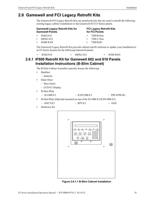
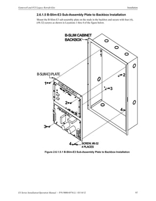
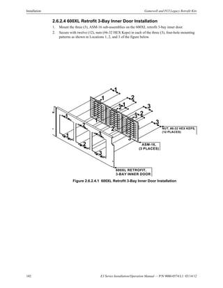
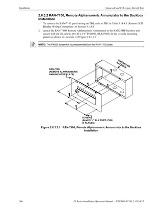
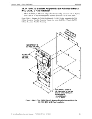
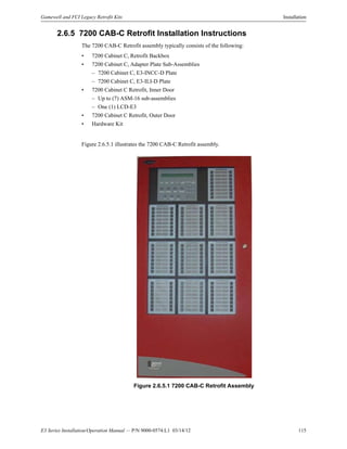
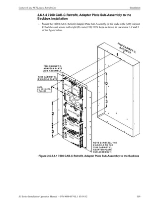
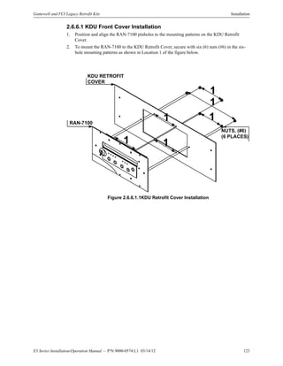
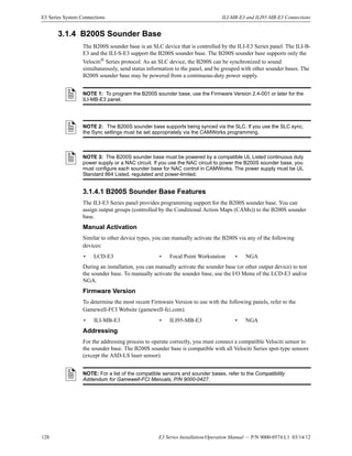
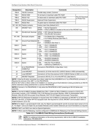
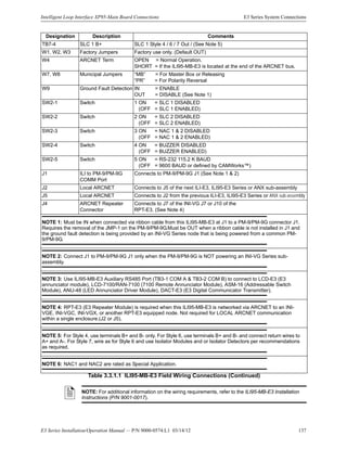
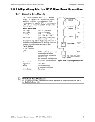
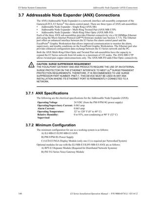
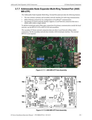
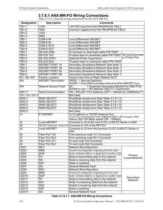
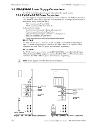
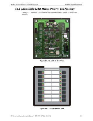
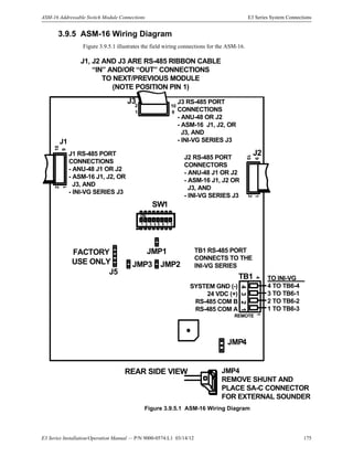
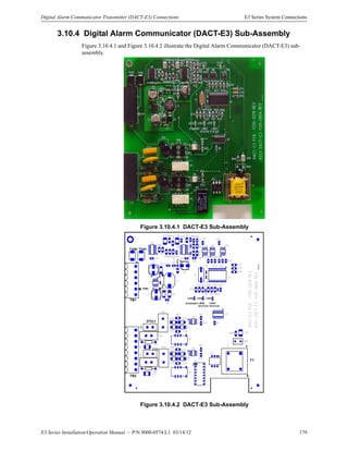
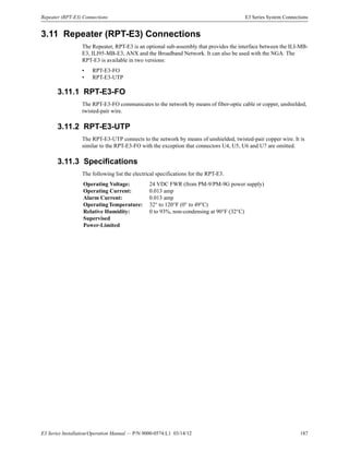
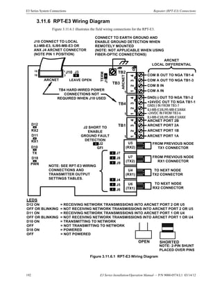
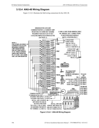
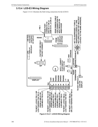
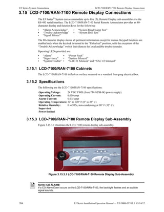
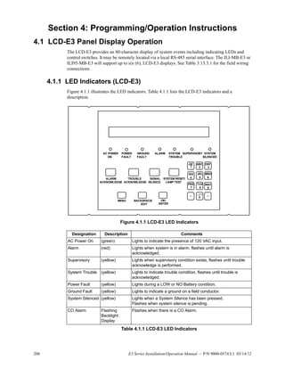
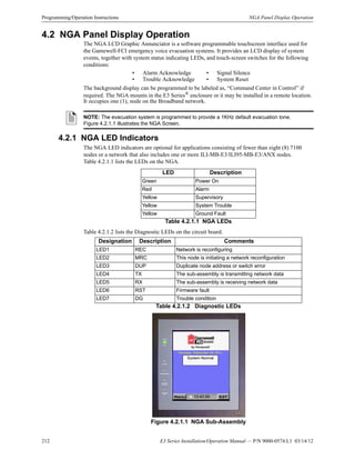
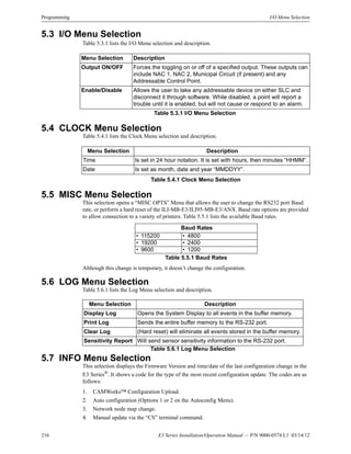
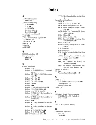
Figure 3.10.5.1.1 illustrates an example of the DACT-E3 Contact ID Reporting Codes for Standard
formats used to configure the following types of systems.
Figure 3.10.5.1.1 Example of the DACT-E3 Contact ID Event Reporting Codes
for Standard Formats
S T A N D A L O N E S Y S T E M S C O N T A C T ID F O R M A T
E X A M P L E
N O T E : G ro u p N u m b e rs a re
tru n c a ted to ran g e [0 0-99].
[1]=N ew Event
[3]=R estoral
Event Type
N ew Event
1
[R ] [E E E ] [00 ]
Fire A larm
110 00
N ot U sed
N ot U sed
C O N T A C T ID F O R M A T
G roup
N um ber
R esponse
Type
G roup 95 Sm oke A larm
S IN G L E -R IN G
N E T W O R K E D S Y S T E M S
C O N T A C T ID F O R M A T
E X A M P L E
1
Fire A larm
110 00
N ew Event
C O N T A C T ID F O R M A T
N ode 25
M U L T I-R IN G
N E T W O R K E D S Y S T E M S C O N T A C T ID F O R M A T
E X A M P L E
[1]=N ew Event
[3]=R estoral
Event Type
N ew Event
1
[R ] [E E E ] [0 N ]
Fire A larm
110 01
N ode
N um ber 100s
C O N T A C T ID F O R M A T
N ode
N um ber
10s & 1s
R esponse
Type
N ode 103
[1]=N ew Event
[3]=R estoral
[R ] [E E E ] [00 ]
Event Type N ode
N um ber
R esponse
Type
N ot U sed
Sm oke A larm
Sm oke A larm
N O T E : T h e 100 s d ig it o f th e n o d e
n u m b er is rep o rted in th e [O N ] field .
N ot U sed
[N N T ]
03 6
[N N T ]
[G G T ]
95 6
25 6](https://image.slidesharecdn.com/e3seriessystem9000-0574-140529161814-phpapp01/85/E3-series-system-9000-0574-180-320.jpg)
![E3 Series Installation/Operation Manual — P/N 9000-0574:L1 03/14/12 181
Digital Alarm Communicator Transmitter (DACT-E3) Connections E3 Series System Connections
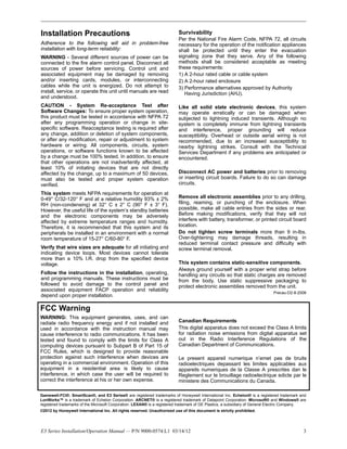
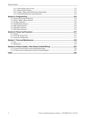
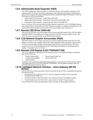
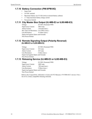
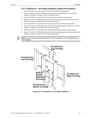
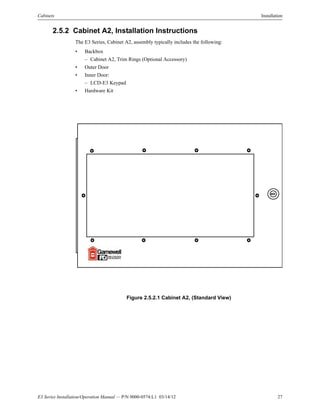
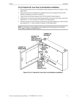
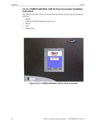
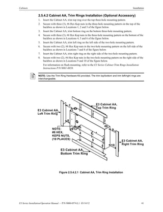
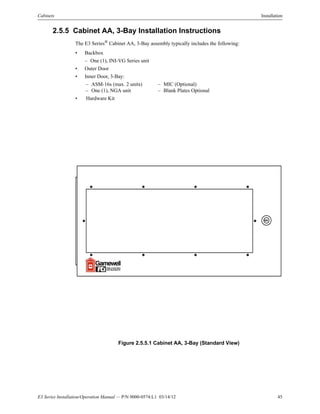
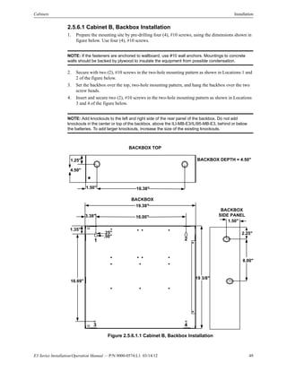
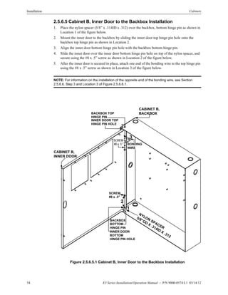
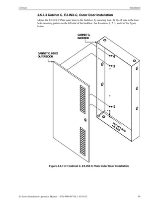
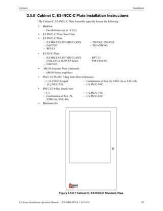
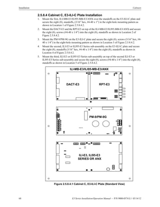
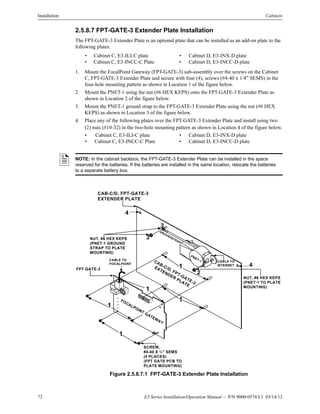
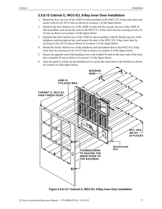
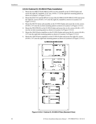
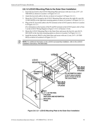
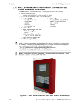
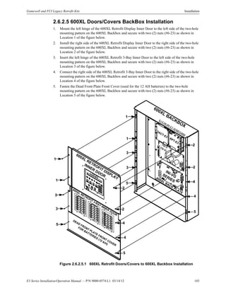
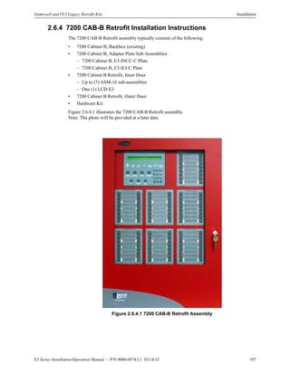
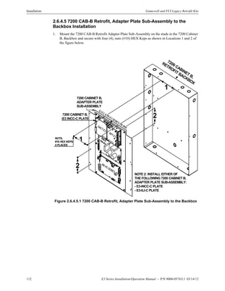
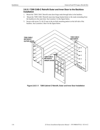
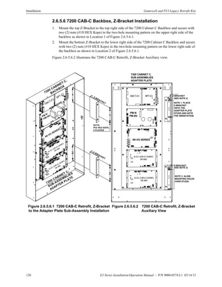
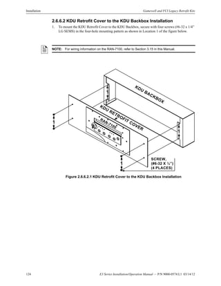
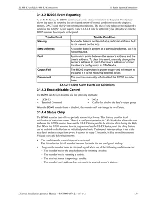
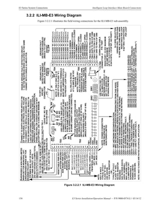
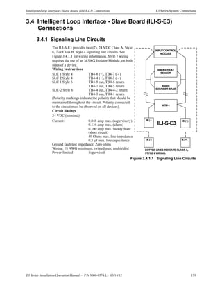
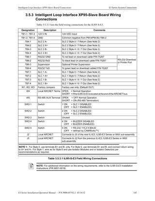
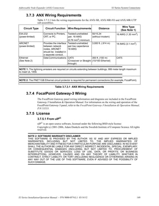
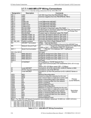
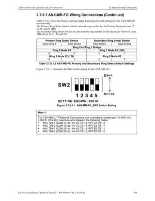
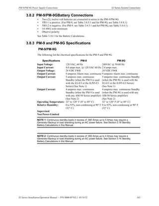
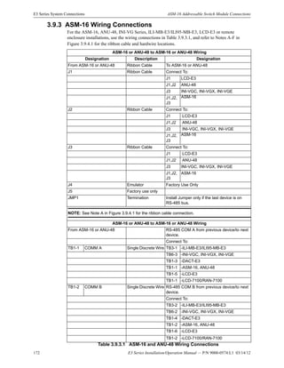
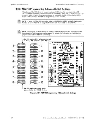
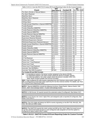
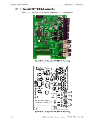
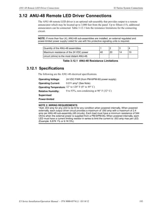
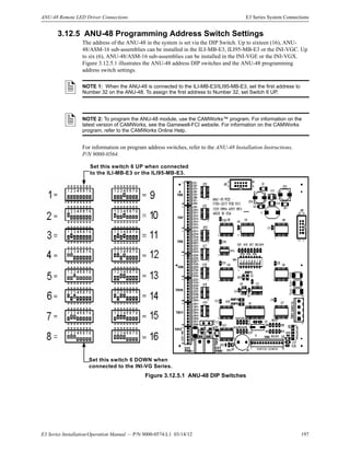
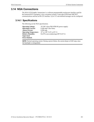
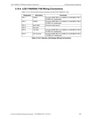
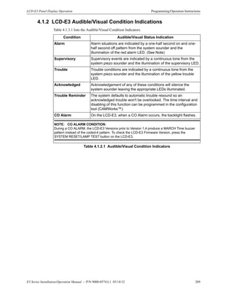
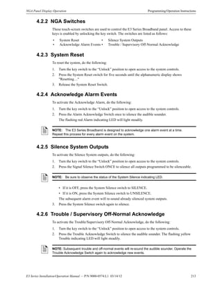
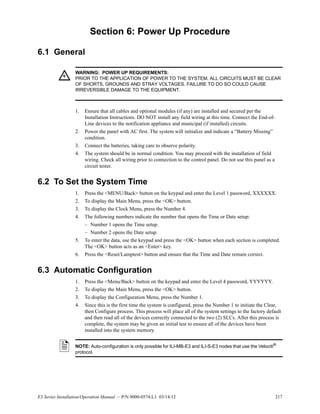
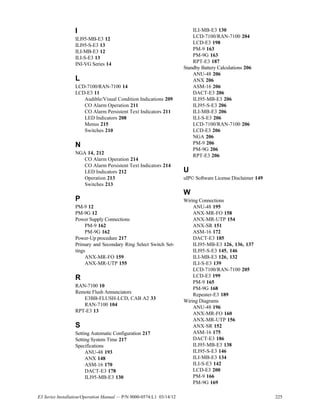
Table 3.10.5.1.1 lists the DACT-E3 Contact ID Event Reporting Codes for the Standard Formats.
Event SIA ContactID 4/2 3/1
Fire Alarm (Smoke or Manual Station) FA [GGT] 1 110 [0G] [GGT] 0 [T] 0
Fire Alarm Restored FH [GGT] 3 110 [0G] [GGT] 2 [T] 2
Waterflow Alarm SA [GGT] 1 113 [0G] [GGT] 0 [T] 0
Waterflow Alarm Restored SH [GGT] 3 113 [0G] [GGT] 2 [T] 2
CO/Gas Alarm GA [GGT] 1 151 [0G] [GGT] 0 [T] 0
CO/Gas Alarm GH [GGT] 3 151 [0G] [GGT] 2 [T] 2
Trouble (except Waterflow or Special AMM/PID) FT [GGT] 1 373 [0G] [GG0] 8 [T] 8
Trouble Restored FJ [GGT] 3 373 [0G] [GG0] 7 [T] 7
Trouble (Waterflow AMM/PID) ST [GGT] 1 370 [0G] [GG0] 8 [T] 8
Trouble Restored (Waterflow AMM/PID) SJ [GGT] 3 203 [0G] [GG0] 7 [T] 7
Trouble (Special AMM/PID) UT [GGT] 1 370 [0G] [GG0] 8 [T] 8
Trouble Restored (Special AMM/PID) UJ [GGT] 3 370 [0G] [GG0] 7 [T] 7
Supervisory / Tamper (Module) SS [GGT] 1 203 [0G] [GGT] 6 [T] 6
Supervisory Restored (Module) SR [GGT] 3 203 [0G] [GGT] 7 [T] 7
PAS/Action/Supervisory (Sensor) FS [GGT] 1 200 [0G] [GGT] 6 [T] 6
PAS/Action/Supervisory Restored (Sensor) FR [GGT] 3 110 [0G] [GGT] 7 [T] 7
Disable (except Waterflow or Special AMM/PID) FB [GGT] 1 571 [0G] [GGT] 8 [T] 8
Disable Restored FU [GGT] 3 571 [0G] [GGT] 7 [T] 7
Disable (Waterflow AMM/PID) SB [GGT] 1 570 [0G] [GGT] 8 [T] 8
Disable Restored (Waterflow AMM/PID) SU [GGT] 3 570 [0G] [GGT] 7 [T] 7
Disable (Special AMM/PID) UB [GGT] 1 570 [0G] [GGT] 8 [T] 8
Disable Restored (Special AMM/PID) UU [GGT] 3 570 [0G] [GGT] 7 [T] 7
AC Fail AT 0 1 301 [0G] [000] 80 8
AC Fail Restored AR 0 3 301 [0G] [000] 70 7
Phone Line 1 Fault LT 1 1 351 [0G] [000] 81 8
Phone Line 1 Fault Restored LR 1 3 351 [0G] [000] 71 7
Phone Line 2 Fault LT 2 1 352 [0G] [000] 82 8
Phone Line 2 Fault Restored LR 2 3 352 [0G] [000] 72 7
Automatic Test (NORMAL) RP 0 1 602 [0G] [000] 90 9
Automatic Test (With Exception) RP 991 1 602 [0G] [991] 91 9
For Contact ID and SIA Formats:
GG = In standalone systems, the group number assigned to the device, 00-99.
= In networked systems, the node number where the device is located, 00-64 (000-122 in
multi-ring networks).
0G = In only multi-ring systems, represents the 100s digit of the node address.
T = Type of device or event causing the event to be reported.
0 = Any Device not listed below
1 = General Alarm Device
2 = Manual Station Alarm
3 = Supervisory Device (Non-latching)
4 = Supervisory Device (Latching)
5 = Waterflow (Non-silenceable)
6 = Smoke Alarm
7 = Non-reporting Device
8 = Multi-level Device
9 = CO/Gas Alarm Device
NOTE 1: Special AMM/PIDs include the following functions: Reset Switch, Silence Switch, Drill
Switch, Alarm Acknowledge Switch, Trouble Acknowledge Switch.
Table 3.10.5.1.1 DACT-E3 Contact ID Event Reporting Codes for Standard Formats](https://image.slidesharecdn.com/e3seriessystem9000-0574-140529161814-phpapp01/85/E3-series-system-9000-0574-181-320.jpg)
![182 E3 Series Installation/Operation Manual — P/N 9000-0574:L1 03/14/12
E3 Series System Connections Digital Alarm Communicator Transmitter (DACT-E3) Connections
3.10.5.2 Custom Formats
The DACT-E3 can be configured to allow each SLC device to report a unique 3-digit code by
selecting the Custom DACT Reporting Feature. The user must specifically enable this feature
through configuration programming using CAMWorks™. If you enable the Custom DACT
Reporting feature, the system uses the Custom codes or optional fields. The system substitutes the
custom formats or optional fields in place of the standard codes. To enable this feature, each ILI-
MB-E3 and ILI-S-E3 must have V2.4-001 or higher ILI Firmware installed. This feature is also
available for the ILI95-MB-E3 and ILI95-S-E3. For information on the DACT-E3 Contact ID
Event Reporting Codes for Custom Formats, refer to Table 3.10.5.2.1.
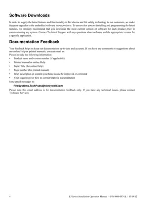
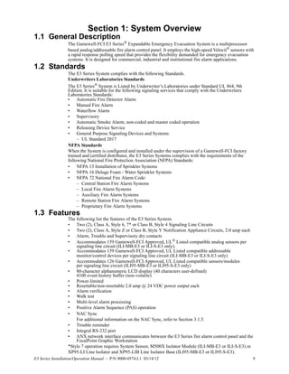
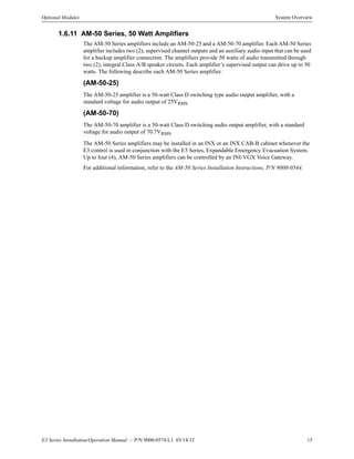
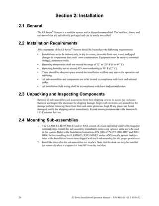
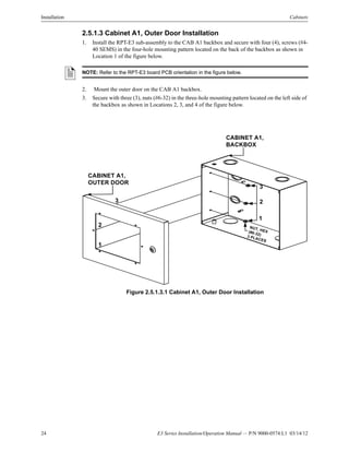
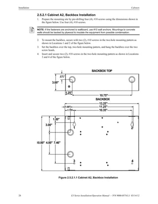
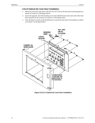
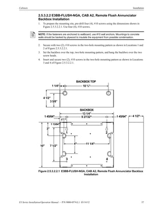
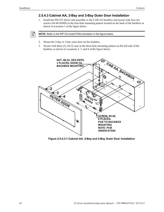
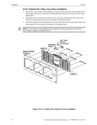
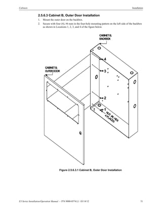
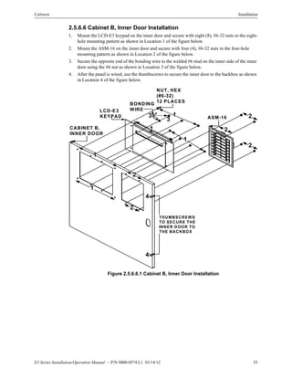
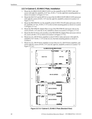
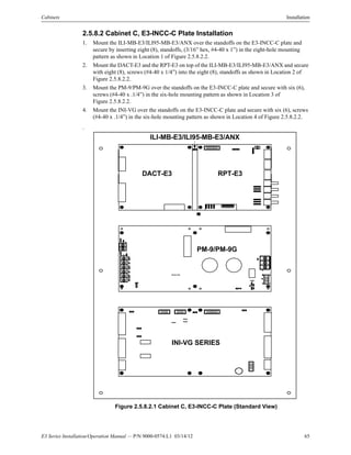
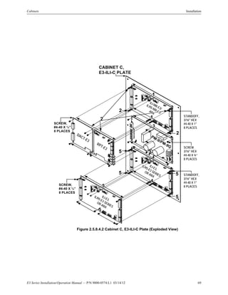
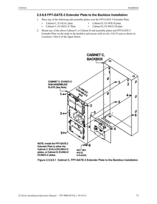
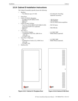
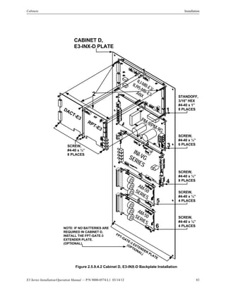
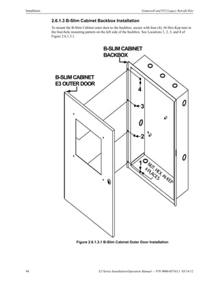
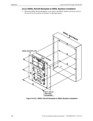
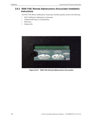
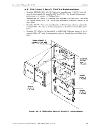
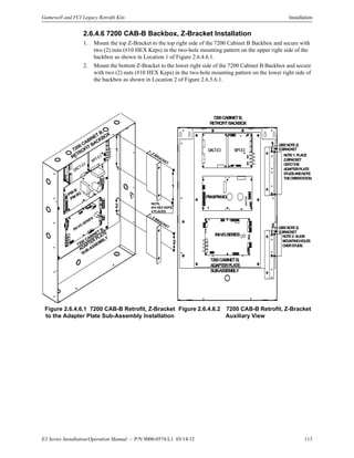
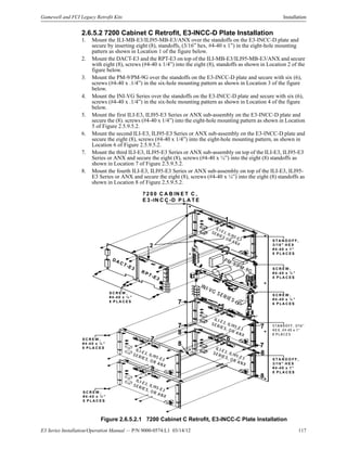
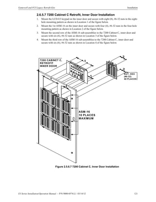
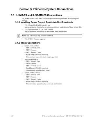
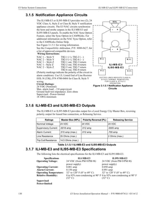
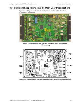
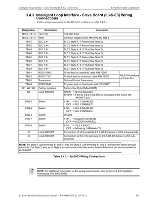
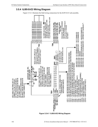
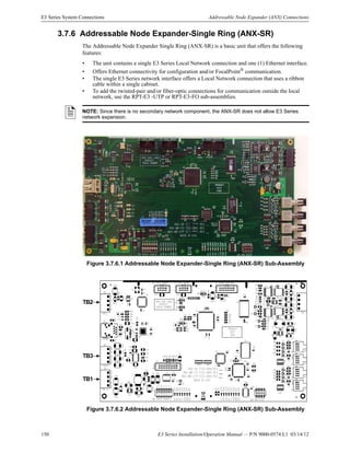
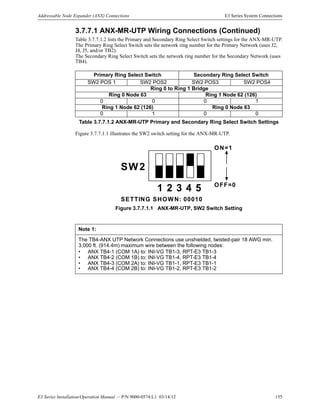
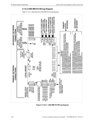
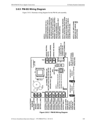
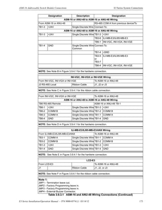
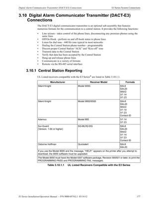
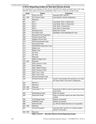
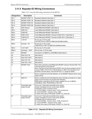
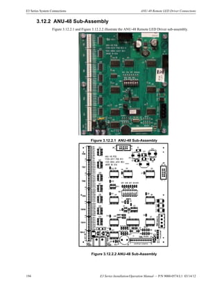
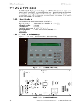
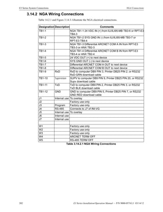
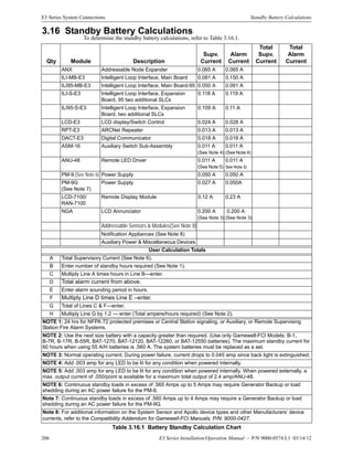
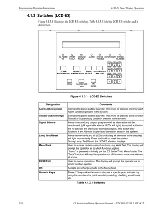
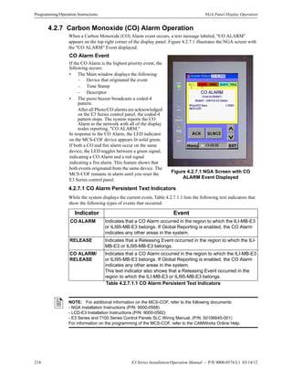
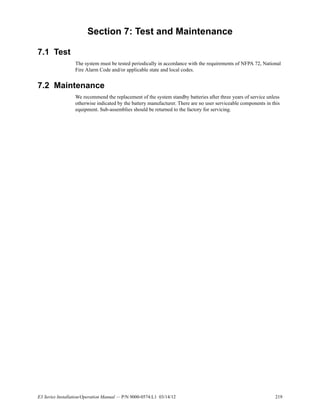
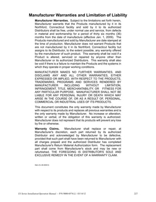
Figure 3.10.5.2.1 illustrates an example of the DACT Contact ID Reporting Codes for Custom
formats used to configure the following types of systems.
Figure 3.10.5.2.1 Example of the DACT-E3 Contact ID Event Reporting Codes
for Custom Formats..
S TA N D A LO N E S Y S T E M S C O N T A C T ID F O R M A T
E X A M P L E
N O T E : G ro u p N u m b ers are
tru n cated to ran ge [00-99].
[1]=New Event
[3]=Restoral
Event Type
New Event
1
[R ] [E E E ] [G G ] [U U U ]
Fire Alarm
110 00 095
G roup 00
G roup
Num ber
C O N T A C T ID F O R M A T
Custom Device ID
S IN G L E -R IN G
N E TW O R K E D S Y S T E M S
C O N T A C T ID F O R M A T
E X A M P L E
1
Fire Alarm
110 09
New Event
C O N T A C T ID F O R M A T
M U L T I-R IN G
N E T W O R K S Y S TE M S C O N T A C T ID F O R M A T
E X A M P L E
[1]=New Event
[3]=Restoral
Event Type
New Event
1
[R ] [E E E ] [N N ]
Fire Alarm
110 09
Node
Num ber
C O N T A C T ID F O R M A T
Node 09
or 109
Node 09
[1]=New Event
[3]=Restoral
[R ] [E E E ] [N N ]
Event Type Node
Num ber
Custom ID 095
500
Custom ID 500
[U U U ]
Custom Device ID
[U U U ]
Custom Device ID
880
Custom ID 880
N O T E : N o de N u m b ers ab o ve 99
are tru n cated to ran g e [00-99].
NOTE: To use the Custom DACT Reporting Feature, all ILI-MB-E3 and ILI-S-E3 nodes on the
network must have V2.4-001 or higher ILI Firmware installed. For additional information, refer to
the CAMWorks Online Help.](https://image.slidesharecdn.com/e3seriessystem9000-0574-140529161814-phpapp01/85/E3-series-system-9000-0574-182-320.jpg)


This document provides important limitations and installation precautions for an Expandable Emergency Evacuation System. It summarizes that while fire alarm systems can detect fires early, they do not ensure protection from fire damage or guarantee warning. Smoke and fire can spread in ways detectors cannot sense. Additionally, the system requires proper installation and maintenance to function correctly.


![[011725].pptx fire safety project alarm](https://cdn.slidesharecdn.com/ss_thumbnails/011725-250411173003-4d91703a-thumbnail.jpg?width=640&height=640&fit=bounds)
![[000417].pptxbasic fire alarm system over](https://cdn.slidesharecdn.com/ss_thumbnails/000417-250411172939-041c5442-thumbnail.jpg?width=640&height=640&fit=bounds)


