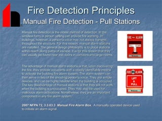
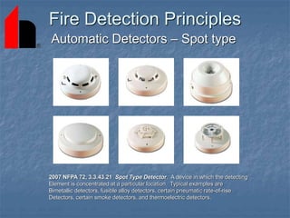
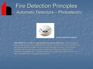
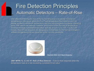
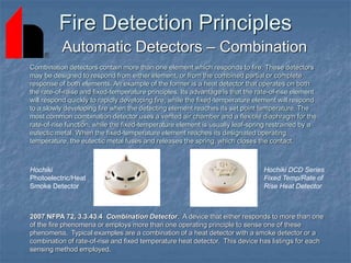
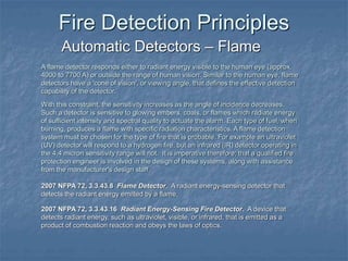
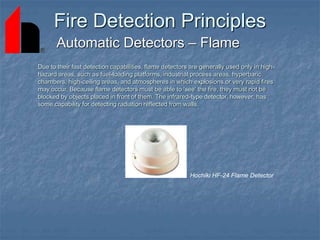
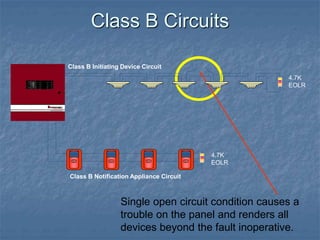
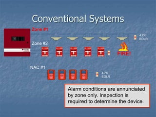
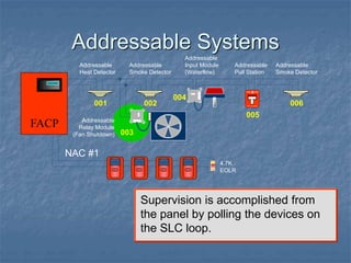
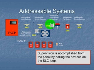
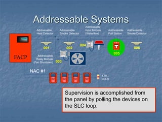
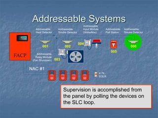
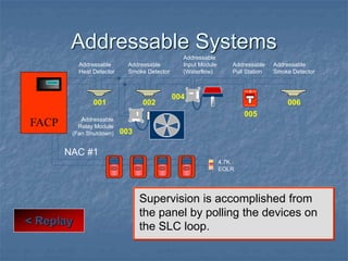
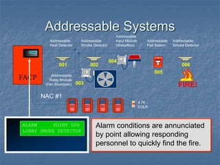
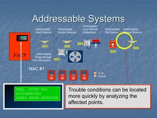
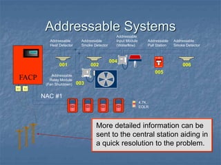
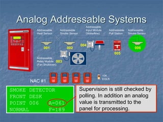
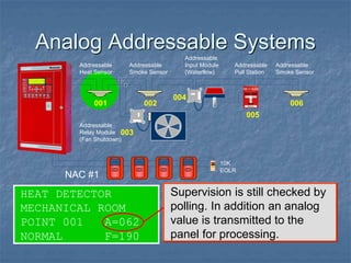
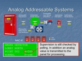
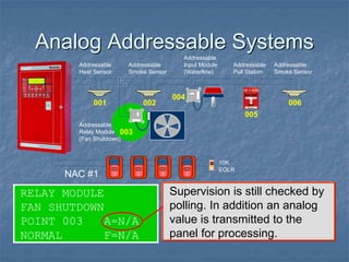
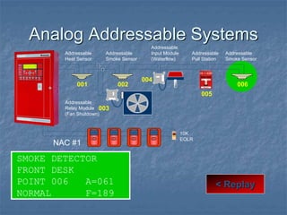
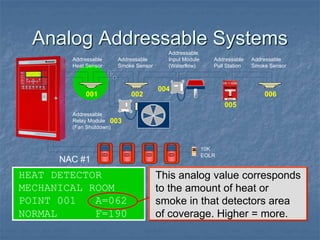
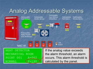
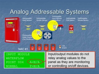
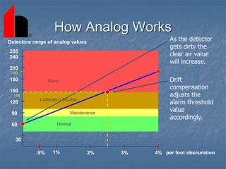
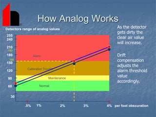
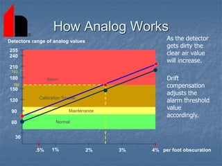
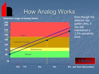
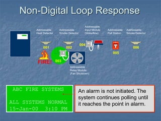
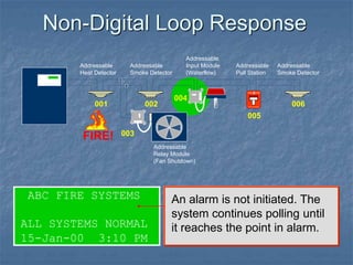
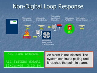
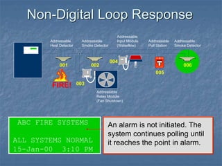
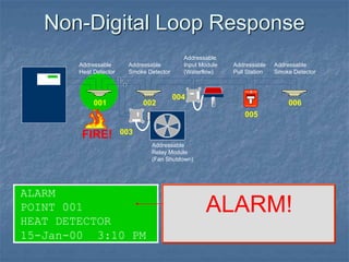
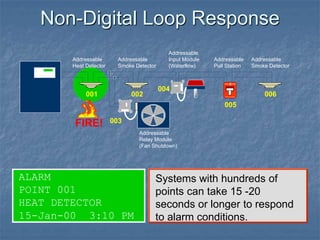
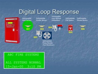
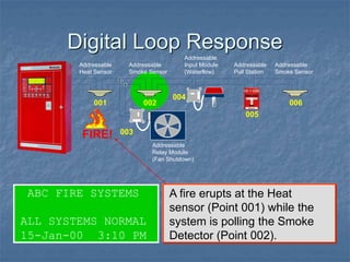
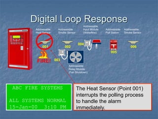
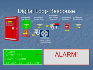
SlideShare a Scribd company logo
1 of 115
Fire Detection and Alarm
System Basics
Hochiki America Corporation
7051 Village Drive, Suite 100
Buena Park, California 90621
www.hochiki.com
Fire Detection and Alarm Systems
A key aspect of fire protection is to identify a developing fire emergency in
a timely manner, and to alert the building's occupants and fire emergency
organizations.
This is the role of fire detection and alarm systems. Depending on the
anticipated fire scenario, building and use type, number and type of
occupants and criticality of contents and mission, these systems can
provide several main functions:
First, they provide a means to identify a developing fire through either
manual or automatic methods.
Second, they alert building occupants to a fire condition and the need to
evacuate.
Another common function is the transmission of an alarm notification signal
to the fire department or other emergency response organization.
They may also shut down electrical, air handling equipment or special
process operations, and they may be used to initiate automatic
suppression systems.
Fire Detection Principles
Manual Fire Detection - Pull Stations
Manual fire detection is the oldest method of detection. In the
simplest form, a person yelling can provide fire warning. In
buildings, however, a person's voice may not always transmit
throughout the structure. For this reason, manual alarm stations
are installed. The general design philosophy is to place stations
within reach along paths of escape. It is for this reason that they
can usually be found near exit doors in corridors and large rooms.
The advantage of manual alarm stations is that, upon discovering
the fire, they provide occupants with a readily identifiable means
to activate the building fire alarm system. The alarm system can
then serve in lieu of the shouting person's voice. They are simple
devices, and can be highly reliable when the building is occupied.
The key disadvantage of manual stations is that they will not work
when the building is unoccupied. They may also be used for
malicious alarm activations. Nonetheless, they are an important
component in any fire alarm system.
2007 NFPA 72, 3.3.63.3 Manual Fire Alarm Box. A manually operated device used
to initiate an alarm signal.
Fire Detection Principles
Automatic Detectors – Spot type
2007 NFPA 72, 3.3.43.21 Spot Type Detector. A device in which the detecting
Element is concentrated at a particular location. Typical examples are
Bimetallic detectors, fusible alloy detectors, certain pneumatic rate-of-rise
Detectors, certain smoke detectors, and thermoelectric detectors.
Fire Detection Principles
Automatic Detectors – Photoelectric
2007 NFPA 72, 3.3.181.4 Light Scattering Smoke Detection. The principle of
using a light source and a photosensitive sensor arranged so that the rays from the
light source do not normally fall onto the photosensitive sensor. When smoke
particles inter the light path, some of the light is scattered by reflection and
refraction onto the sensor. The light signal is processed and used to convey an
alarm condition when it meets preset criteria.
Hochiki SLR-24V detector
Fire Detection Principles
Automatic Detectors – Photoelectric
A – Light Source
B – Photo Sensor
In the normal case, the light from the light source on the left shoots straight
across and misses the sensor.
When smoke enters the chamber, however, the smoke particles scatter the
light and some amount of light hits the sensor.
Fire Detection Principles
Automatic Detectors – Ionization
Ionization smoke detectors use an ionization chamber and a source of ionizing radiation
to detect smoke. This type of smoke detector is more common because it is inexpensive and
better at detecting the smaller amounts of smoke produced by flaming fires.
Inside the ionization detector is a small amount (perhaps 1/5000th of a gram) of Americium-
241. The radioactive element americium has a half-life of 432 years, and is a good source of
alpha particles.
An ionization chamber is very simple. It consists of two plates with a voltage across them,
along with a radioactive source of ionizing radiation.
2007 NFPA 72, 3.3.181.2 Ionization Smoke Detection. The principle of using a small amount of
radioactive material to ionize the air between two differentially charged electrodes to sense the
presence of smoke particles. Smoke Particles entering the ionization volume decrease the
conductance of the air by reducing ion mobility. The reduced conductance signal is processed and
used to convey an alarm condition when it meets preset criteria.
Hochiki SIJ-24 detector
Fire Detection Principles
Automatic Detectors – Ionization
Ionization Smoke detectors
The alpha particles generated by the americium have the following property: They ionize the
oxygen and nitrogen atoms of the air in the chamber. To "ionize" means to "knock an electron off
of." When you knock an electron off of an atom, you end up with a free electron (with a negative
charge) and an atom missing one electron (with a positive charge). The negative electron is
attracted to the plate with a positive voltage, and the positive atom is attracted to the plate with a
negative voltage (opposites attract, just like with magnets). The electronics in the smoke detector
sense the small amount of electrical current that these electrons and ions moving toward the
plates represent.
When smoke enters the ionization chamber, it disrupts this current -- the smoke particles attach
to the ions and neutralize them. The smoke detector senses the drop in current between the
plates and sets off the horn.
Fire Detection Principles
Automatic Detectors – Heat/Thermal
2007 NFPA 72, 3.3.43.9 Heat Detector. A fire detector that detects either abnormally
high temperature, or rate of temperature rise, or both.
Heat detectors are the oldest type of automatic fire detection device. They began
development of automatic sprinklers in the 1860s and have continued to the present
with proliferation of various types of devices.
Heat detectors that only initiate an alarm and have no extinguishing function are still in use.
Although they have the lowest false alarm rate of all automatic fire detector devices, they
also are the slowest in fire detecting. A heat detector is best situated for fire detection in a
small confined space where rapidly building high-output fires are expected, in areas where
ambient conditions would not allow the use of other fire detection devices, or when speed of
detection is not a prime consideration.
Heat detectors are generally located on or near the ceiling and respond to the convected
thermal energy of a fire. They respond either when the detecting element reaches a
predetermined fixed temperature or to a specified rate of temperature change. In general,
heat detectors are designed to operate when heat causes a prescribed change in a
physical or electrical property of a material or gas.
Heat detectors can be sub-divided by their operating principles:
Fire Detection Principles
Automatic Detectors – Fixed Temp.
2007 NFPA 72, 3.3.43.7 Fixed-Temperature Detector. A device that responds when
its operating element becomes heated to a predetermined level.
Fixed-temperature heat detectors are designed to alarm when the temperature of the
operating elements reaches a specific point. The air temperature at the time of alarm is
usually considerably higher than the rated temperature because it takes time for the air
to raise the temperature of the operating element to its set point. This condition is called
thermal lag. Fixed-temperature heat detectors are available to cover a wide range of
operating temperatures - from about 135'F (57'C) and higher. Higher temperatures
detectors are also necessary so that detection can be provided in areas normally subject
to high ambient temperatures, or in areas zoned so that only detectors in the immediate
fire area operate.
Hochiki DFE Series Heat Detector
Fire Detection Principles
Automatic Detectors – Rate-of-Rise
2007 NFPA 72, 3.3.43.18 Rate-of-Rise Detector. A device that responds when the
temperature rises at a rate exceeding a predetermined value
One effect that flaming fire has on the surrounding area is to rapidly increase air
temperature in the space above the fire. Fixed-temperature heat detectors will not
initiate an alarm until the air temperature near the ceiling exceeds the design operating
point. The rate-of-rise detector, however, will function when the rate of temperature
increase exceeds a predetermined value, typically around 12 to 15'F (7 to 8'C) per
minute. Rate-of-rise detectors are designed to compensate for the normal changes in
ambient temperature that are expected under non-fire conditions.
Hochiki DSC-EA Heat Detector
Fire Detection Principles
Automatic Detectors – Combination
2007 NFPA 72, 3.3.43.4 Combination Detector. A device that either responds to more than one
of the fire phenomena or employs more than one operating principle to sense one of these
phenomena. Typical examples are a combination of a heat detector with a smoke detector or a
combination of rate-of-rise and fixed temperature heat detector. This device has listings for each
sensing method employed.
Combination detectors contain more than one element which responds to fire. These detectors
may be designed to respond from either element, or from the combined partial or complete
response of both elements. An example of the former is a heat detector that operates on both
the rate-of-raise and fixed-temperature principles. Its advantage is that the rate-of-rise element
will respond quickly to rapidly developing fire, while the fixed-temperature element will respond
to a slowly developing fire when the detecting element reaches its set point temperature. The
most common combination detector uses a vented air chamber and a flexible diaphragm for the
rate-of-rise function, while the fixed-temperature element is usually leaf-spring restrained by a
eutectic metal. When the fixed-temperature element reaches its designated operating
temperature, the eutectic metal fuses and releases the spring, which closes the contact.
Hochiki DCD Series
Fixed Temp/Rate of
Rise Heat Detector
Hochiki
Photoelectric/Heat
Smoke Detector
Fire Detection Principles
Automatic Detectors – Flame
2007 NFPA 72, 3.3.43.8 Flame Detector. A radiant energy-sensing detector that
detects the radiant energy emitted by a flame.
2007 NFPA 72, 3.3.43.16 Radiant Energy-Sensing Fire Detector. A device that
detects radiant energy, such as ultraviolet, visible, or infrared, that is emitted as a
product of combustion reaction and obeys the laws of optics.
A flame detector responds either to radiant energy visible to the human eye (approx.
4000 to 7700 A) or outside the range of human vision. Similar to the human eye, flame
detectors have a 'cone of vision', or viewing angle, that defines the effective detection
capability of the detector.
With this constraint, the sensitivity increases as the angle of incidence decreases.
Such a detector is sensitive to glowing embers, coals, or flames which radiate energy
of sufficient intensity and spectral quality to actuate the alarm. Each type of fuel, when
burning, produces a flame with specific radiation characteristics. A flame detection
system must be chosen for the type of fire that is probable. For example an ultraviolet
(UV) detector will respond to a hydrogen fire, but an infrared (IR) detector operating in
the 4.4 micron sensitivity range will not. It is imperative therefore; that a qualified fire
protection engineer is involved in the design of these systems, along with assistance
from the manufacturer's design staff.
Fire Detection Principles
Automatic Detectors – Flame
Due to their fast detection capabilities, flame detectors are generally used only in high-
hazard areas, such as fuel-loading platforms, industrial process areas, hyperbaric
chambers, high-ceiling areas, and atmospheres in which explosions or very rapid fires
may occur. Because flame detectors must be able to 'see' the fire, they must not be
blocked by objects placed in front of them. The infrared-type detector, however, has
some capability for detecting radiation reflected from walls.
Hochiki HF-24 Flame Detector
Fire Detection Principles
Automatic Detectors – Linear Type
2007 NFPA 72, 3.3.43.10 Line-Type Detector. A device in which detection is continuous
along a path. Typical examples are rate-of-rise pneumatic tubing detectors, projected
beam smoke detectors, and heat sensitive cable.
2007 NFPA 72, 3.3.43.15 Projected Beam-Type Detector. A type of photoelectric light
obscuration smoke detector wherein the beam spans the protected area.
2007 NFPA 72, 3.3.181.3 Photoelectric Light Obscuration Detection. The principle
of using a light source and a photosensitive sensor onto which the principal portion of
the source emission is focused. When smoke particles enter the light path, some of the
light is scattered and some of the light is absorbed, thereby reducing the light reaching
the receiving sensor. The light reduction signal is processed and used to convey an
alarm condition when it meets preset criteria.
Fire Detection Principles
Automatic Detectors – Air Sampling
2007 NFPA 72, 3.3.43.1 Air Sampling-Type Detector. A detector that
consists of a piping or tubing distribution network that runs from the detector to
the area(s) to be protected. An aspiration fan in the detector draws air form the
protected area back to the detector through air sampling ports, piping, or
tubing. At the detector, the air is analyzed for fire products.
Building Notification
Notification Appliances
2007 NFPA 72, 3.3.113 Notification Appliance. A fire alarm system
component such as a bell, horn, speaker, light or text display that provides
audible, tactile, or visible outputs, or any combination thereof.
2007 NFPA 72, 3.3.113.1 Audible Notification Appliance. A notification
appliance that alerts by the sense of hearing.
2007 NFPA 72, 3.3.113.3 Visible Notification Appliance. A notification
appliance that alerts by the sense of sight.
Fire Alarm Circuit Classes
2007 NFPA 72, 6.4.2.1 Class. Initiating device circuits, notification appliance
circuits, and signaling line circuits shall be permitted to be designated as either
Class A or Class B, depending on their performance during nonsimultaneous
single circuit fault conditions as specified by the following:
(1) Initiating device circuits and signaling line circuits that transmit an alarm or
supervisory signal, or notification appliance circuits that allow all connected
devices to operate during a single open or a nonsimultaneous single ground
fault on any circuit conductor, shall be designated as Class A
(2) Initiating device circuits and signaling line circuits that do not transmit an
alarm or supervisory signal, or notification appliance circuits that do not allow
all connected devices to operate beyond the location of a single open on any
circuit conductor, shall be designated as Class B
2007 NFPA 72, 6.4.2.2. An open or ground fault condition shall result in the
annunciation of a trouble signal at the protected premise within 200 seconds as
required in 4.4.7
Class B Initiating Device Circuit
4.7K
EOLR
4.7K
EOLR
Class B Notification Appliance Circuit
Class B Circuits
End of line supervision resistors
are required to supervise the
integrity of the loop.
Single open circuit condition causes a
trouble on the panel and renders all
devices beyond the fault inoperative.
Class B Initiating Device Circuit
4.7K
EOLR
4.7K
EOLR
Class B Notification Appliance Circuit
Class B Circuits
Class A Initiating Device Circuit
Class A Notification Appliance Circuit
Class A Circuits
End of line supervision resistors are not
necessary as the loop returns to the
panel and is driven from both ends.
Class A Initiating Device Circuit
Class A Notification Appliance Circuit
Class A Circuits
Single open circuit condition causes a
trouble on the panel. All devices on the
loop remain operative.
Addressable Device - A fire alarm system component with discreet identification that can
have its status individually identified or that is used to individually control other functions.
Analog Addressable Sensor - An initiating device that transmits a signal indicating varying
degrees of condition as contrasted with a conventional or addressable initiating device, which
can only indicate an off/on condition.
Signaling Line Circuit (SLC) - A circuit or path between any combination of circuit interfaces,
control units, or transmitters over which multiple system input signals or out put signals or
both are carried.
SLC Interface - A system component that connects a signaling line circuit to any
combination of initiating devices, initiating device circuits, notification appliances,
notification appliance circuits, system control outputs and other signaling line
circuits.
Protocol - A language for communicating between control panels and their proprietary devices.
Additional Fire Alarm Terminology
 Conventional control panels range in size from 1 zone
to over 100 zones.
 Zones typically consist of some or all of the initiating
devices in an area or floor of a building.
 Some control panels zone capacity is expandable
while others are not, limiting its usefulness if a facility
adds additional buildings or rooms.
Comparing System Types
To better understand today’s newer technology, a firm understanding of the types of systems
available is necessary. The three most popular types of systems installed today are:
•Conventional
•Addressable
•Analog Addressable
Conventional Systems
Zone 1
4.7K
EOLR
Zone 2
FIRE
FIRE
SILENT KNIGHT
FIRE
FIRE
SILENT KNIGHT
FIRE
FIRE
SILENT KNIGHT
FIRE
FIRE
SILENT KNIGHT
FIRE
FIRE
SILENT KNIGHT
FACP
NAC 1
Multiple devices are combined
into a single zone. Zones can
contain 30 or more devices.
4.7K
EOLR
Conventional Systems
Care must be taken when laying
out zones to comply with code
requirements.
Zone 1
4.7K
EOLR
Zone 2
FIRE
FIRE
SILENT KNIGHT
NAC 1
4.7K
EOLR
Zone Considerations
 2007 NFPA 72 6.8.5.5.2 Limits the number of waterflow
switches in a single zone to 5.
 2007 NFPA 72 6.8.5.6.2 Limits the number of
supervisory devices in a single zone to 20.
 2007 NFPA 72 Annex A.4.4.6.6 Suggests that the
maximum number of square feet in a single zone be
limited to no more than 22,500.
Conventional Systems
Wiring must be installed in a
supervised manner either Class A,
or Class B with an EOLR.
Zone #1
4.7K
EOLR
4.7K
EOLR
Zone #2
NAC #1
Conventional Systems
Alarm conditions are annunciated
by zone only. Inspection is
required to determine the device.
Zone #1
4.7K
EOLR
4.7K
EOLR
Zone #2
NAC #1
FIRE!
Conventional Systems
Trouble conditions are annunciated
by zone only. Inspection is required
to determine the cause.
4.7K
EOLR
Zone #1
4.7K
EOLR
4.7K
EOLR
Zone #2
NAC #1
Conventional Systems
Information transmitted to the central
station is by zone at best. Many
panels send Alarm, Supv, Trbl only.
RJ RJ
Zone #1
4.7K
EOLR
4.7K
EOLR
Zone #2
NAC #1
Addressable Systems
 An addressable systems point capacity is
determined by the amount of SLC “Signaling
Line Circuits” it contains.
 Each SLC circuit provides power,
communication, & supervision for all of the
devices connected to it.
 Each SLC can accommodate over 100
addressable devices, depending upon the
manufacturer.
FACP
Addressable Systems
FACP
Each SLC loop can contain a variety of
addressable devices. Non-addressable devices
are connected via addressable module.
FIRE
FIRE
SILENT KNIGHT
Addressable
Pull Station
Addressable
Heat Detector
4.7K
EOLR
NAC #1
Addressable
Smoke Detector
Addressable
Input Module
(Waterflow)
Addressable
Smoke Detector
Addressable
Relay Module
(Fan Shutdown)
Addressable Systems
Each point on the SLC loop is given
a unique address when installed.
001 002
003
004
005
006
FACP
FIRE
FIRE
SILENT KNIGHT
Addressable
Pull Station
Addressable
Relay Module
(Fan Shutdown)
Addressable
Heat Detector
4.7K
EOLR
NAC #1
Addressable
Smoke Detector
Addressable
Input Module
(Waterflow)
Addressable
Smoke Detector
Addressable Systems
Supervision is accomplished from
the panel by polling the devices on
the SLC loop.
001 002
003
004
005
006
FACP
FIRE
FIRE
SILENT KNIGHT
Addressable
Pull Station
Addressable
Relay Module
(Fan Shutdown)
Addressable
Heat Detector
4.7K
EOLR
Addressable
Smoke Detector
Addressable
Input Module
(Waterflow)
Addressable
Smoke Detector
NAC #1
Addressable Systems
Supervision is accomplished from
the panel by polling the devices on
the SLC loop.
001 002
003
004
005
006
FIRE
FIRE
SILENT KNIGHT
Addressable
Pull Station
Addressable
Relay Module
(Fan Shutdown)
Addressable
Heat Detector
4.7K
EOLR
Addressable
Smoke Detector
Addressable
Input Module
(Waterflow)
Addressable
Smoke Detector
FACP
NAC #1
Addressable Systems
Supervision is accomplished from
the panel by polling the devices on
the SLC loop.
< Replay
001 002
003
004
005
006
FACP
FIRE
FIRE
SILENT KNIGHT
Addressable
Pull Station
Addressable
Relay Module
(Fan Shutdown)
Addressable
Heat Detector
4.7K
EOLR
Addressable
Smoke Detector
Addressable
Input Module
(Waterflow)
Addressable
Smoke Detector
NAC #1
Addressable Systems
Alarm conditions are annunciated
by point allowing responding
personnel to quickly find the fire.
ALARM POINT 006
LOBBY SMOKE DETECTOR
001 002
003
004
005
006
FACP
FIRE
FIRE
SILENT KNIGHT
Addressable
Pull Station
Addressable
Relay Module
(Fan Shutdown)
Addressable
Heat Detector
4.7K
EOLR
Addressable
Smoke Detector
Addressable
Input Module
(Waterflow)
Addressable
Smoke Detector
NAC #1
FIRE!
Addressable Systems
Trouble conditions can be located
more quickly by analyzing the
affected points.
TRBL POINT 006
DISCONNECTED
LOBBY SMOKE DETECTOR
001 002
003
004
005
006
FACP
FIRE
FIRE
SILENT KNIGHT
Addressable
Pull Station
Addressable
Relay Module
(Fan Shutdown)
Addressable
Heat Detector
4.7K
EOLR
Addressable
Smoke Detector
Addressable
Input Module
(Waterflow)
Addressable
Smoke Detector
NAC #1
Addressable Systems
More detailed information can be
sent to the central station aiding in
a quick resolution to the problem.
RJ
RJ
001 002
003
004
005
006
FACP
FIRE
FIRE
SILENT KNIGHT
Addressable
Pull Station
Addressable
Relay Module
(Fan Shutdown)
Addressable
Heat Detector
4.7K
EOLR
Addressable
Smoke Detector
Addressable
Input Module
(Waterflow)
Addressable
Smoke Detector
NAC #1
Addressable Systems
Since supervision is accomplished
through polling, t-tapped wiring is
permitted. (Class B wiring)
001 002
003
004
005
006
FACP
FIRE
FIRE
SILENT KNIGHT
Addressable
Pull Station
Addressable
Relay Module
(Fan Shutdown)
Addressable
Heat Detector
4.7K
EOLR
Addressable
Smoke Detector
Addressable
Input Module
(Waterflow)
Addressable
Smoke Detector
NAC #1
Addressable Systems
Many systems support flexible
input/output programming to link
initiating devices to outputs.
001 002
003
004
005
006
FACP
FIRE
FIRE
SILENT KNIGHT
Addressable
Pull Station
Addressable
Relay Module
(Fan Shutdown)
Addressable
Heat Detector
4.7K
EOLR
Addressable
Smoke Detector
Addressable
Input Module
(Waterflow)
Addressable
Smoke Detector
NAC #1
FIRE!
Comparison
 Conventional
 Lower initial
equipment costs.
 Wide range of
compatible devices.
 Can be easier to
program.
 Limited expansion
capability.
 Addressable
 Easier to install.
 More system status
information at the
panel and central
station.
 Input/Output
programming much
more flexible.
 Usually much more
room available to
expand.
Analog Addressable Systems
 Detectors in an analog addressable systems
become “sensors” relaying information to the
control panel corresponding to how much
smoke or heat that detector is sensing.
 The control panel makes the decisions based
on this information when to alarm etc.
Analog Addressable Systems
Addressable
Relay Module
(Fan Shutdown)
Addressable
Heat Sensor
10K
EOLR
Addressable
Smoke Sensor
Addressable
Input Module
(Waterflow)
001 002
003
004
005
Addressable
Pull Station
Addressable
Smoke Sensor
006
HEAT DETECTOR
MECHANICAL ROOM
POINT 001 A=062
NORMAL F=190
Supervision is still checked by
polling. In addition an analog
value is transmitted to the
panel for processing.
NAC #1
Analog Addressable Systems
SMOKE DETECTOR
LOBBY NORTH
POINT 002 A=060
NORMAL F=188
Supervision is still checked by
polling. In addition an analog
value is transmitted to the
panel for processing.
Addressable
Relay Module
(Fan Shutdown)
Addressable
Heat Sensor
Addressable
Smoke Sensor
Addressable
Input Module
(Waterflow)
001 002
003
004
005
Addressable
Pull Station
Addressable
Smoke Detector
006
10K
EOLR
NAC #1
Analog Addressable Systems
RELAY MODULE
FAN SHUTDOWN
POINT 003 A=N/A
NORMAL F=N/A
Supervision is still checked by
polling. In addition an analog
value is transmitted to the
panel for processing.
Addressable
Relay Module
(Fan Shutdown)
Addressable
Heat Sensor
Addressable
Smoke Sensor
Addressable
Input Module
(Waterflow)
001 002
003
004
005
Addressable
Pull Station
Addressable
Smoke Sensor
006
10K
EOLR
NAC #1
Analog Addressable Systems
INPUT MODULE
WATERFLOW
POINT 004 A=N/A
NORMAL F=N/A
Supervision is still checked by
polling. In addition an analog
value is transmitted to the
panel for processing.
Addressable
Relay Module
(Fan Shutdown)
Addressable
Heat Sensor
Addressable
Smoke Sensor
Addressable
Input Module
(Waterflow)
001 002
003
004
005
Addressable
Pull Station
Addressable
Smoke Sensor
006
10K
EOLR
NAC #1
Analog Addressable Systems
Supervision is still checked by
polling. In addition an analog
value is transmitted to the
panel for processing.
INPUT MODULE
MANUAL PULL
POINT 005 A=N/A
NORMAL F=N/A
Addressable
Relay Module
(Fan Shutdown)
Addressable
Heat Sensor
Addressable
Smoke Sensor
Addressable
Input Module
(Waterflow)
001 002
003
004
005
Addressable
Pull Station
Addressable
Smoke Sensor
006
10K
EOLR
NAC #1
Analog Addressable Systems
SMOKE DETECTOR
FRONT DESK
POINT 006 A=061
NORMAL F=189
Supervision is still checked by
polling. In addition an analog
value is transmitted to the
panel for processing.
Addressable
Relay Module
(Fan Shutdown)
Addressable
Heat Sensor
Addressable
Smoke Sensor
Addressable
Input Module
(Waterflow)
001 002
003
004
005
Addressable
Pull Station
Addressable
Smoke Sensor
006
10K
EOLR
NAC #1
Analog Addressable Systems
HEAT DETECTOR
MECHANICAL ROOM
POINT 001 A=062
NORMAL F=190
Supervision is still checked by
polling. In addition an analog
value is transmitted to the
panel for processing.
Addressable
Relay Module
(Fan Shutdown)
Addressable
Heat Sensor
Addressable
Smoke Sensor
Addressable
Input Module
(Waterflow)
001 002
003
004
005
Addressable
Pull Station
Addressable
Smoke Sensor
006
10K
EOLR
NAC #1
Analog Addressable Systems
SMOKE DETECTOR
LOBBY NORTH
POINT 002 A=060
NORMAL F=188
Supervision is still checked by
polling. In addition an analog
value is transmitted to the
panel for processing.
Addressable
Relay Module
(Fan Shutdown)
Addressable
Heat Sensor
Addressable
Smoke Sensor
Addressable
Input Module
(Waterflow)
001 002
003
004
005
Addressable
Pull Station
Addressable
Smoke Sensor
006
10K
EOLR
NAC #1
Analog Addressable Systems
RELAY MODULE
FAN SHUTDOWN
POINT 003 A=N/A
NORMAL F=N/A
Supervision is still checked by
polling. In addition an analog
value is transmitted to the
panel for processing.
Addressable
Relay Module
(Fan Shutdown)
Addressable
Heat Sensor
Addressable
Smoke Sensor
Addressable
Input Module
(Waterflow)
001 002
003
004
005
Addressable
Pull Station
Addressable
Smoke Sensor
006
10K
EOLR
NAC #1
Analog Addressable Systems
INPUT MODULE
WATERFLOW
POINT 004 A=N/A
NORMAL F=N/A
Supervision is still checked by
polling. In addition an analog
value is transmitted to the
panel for processing.
Addressable
Relay Module
(Fan Shutdown)
Addressable
Heat Sensor
Addressable
Smoke Sensor
Addressable
Input Module
(Waterflow)
001 002
003
004
005
Addressable
Pull Station
Addressable
Smoke Sensor
006
10K
EOLR
NAC #1
Analog Addressable Systems
Supervision is still checked by
polling. In addition an analog
value is transmitted to the
panel for processing.
INPUT MODULE
MANUAL PULL
POINT 005 A=N/A
NORMAL F=N/A
Addressable
Relay Module
(Fan Shutdown)
Addressable
Heat Sensor
Addressable
Smoke Sensor
Addressable
Input Module
(Waterflow)
001 002
003
004
005
Addressable
Pull Station
Addressable
Smoke Sensor
006
10K
EOLR
NAC #1
Analog Addressable Systems
SMOKE DETECTOR
FRONT DESK
POINT 006 A=061
NORMAL F=189
< Replay
Addressable
Relay Module
(Fan Shutdown)
Addressable
Heat Sensor
Addressable
Smoke Sensor
Addressable
Input Module
(Waterflow)
001 002
003
004
005
Addressable
Pull Station
Addressable
Smoke Sensor
006
10K
EOLR
NAC #1
Analog Addressable Systems
This analog value corresponds
to the amount of heat or
smoke in that detectors area
of coverage. Higher = more.
HEAT DETECTOR
MECHANICAL ROOM
POINT 001 A=062
NORMAL F=190
Addressable
Relay Module
(Fan Shutdown)
Addressable
Heat Sensor
Addressable
Smoke Sensor
Addressable
Input Module
(Waterflow)
001 002
003
004
005
Addressable
Pull Station
Addressable
Smoke Sensor
006
10K
EOLR
NAC #1
Analog Addressable Systems
If the analog value exceeds
the alarm threshold, an alarm
occurs. This alarm threshold is
calculated by the panel.
HEAT DETECTOR
MECHANICAL ROOM
POINT 001 A=062
NORMAL F=190
Addressable
Relay Module
(Fan Shutdown)
Addressable
Heat Sensor
Addressable
Smoke Sensor
Addressable
Input Module
(Waterflow)
001 002
003
004
005
Addressable
Pull Station
Addressable
Smoke Sensor
006
10K
EOLR
NAC #1
Analog Addressable Systems
INPUT MODULE
WATERFLOW
POINT 004 A=N/A
NORMAL F=N/A
Input/output modules do not
relay analog values to the
panel as they are monitoring
or controlling on/off devices.
Addressable
Relay Module
(Fan Shutdown)
Addressable
Heat Sensor
Addressable
Smoke Sensor
Addressable
Input Module
(Waterflow)
001 002
003
004
005
Addressable
Pull Station
Addressable
Smoke Sensor
006
10K
EOLR
NAC #1
Analog Addressable
Features
 An analog addressable control panel is capable of
several enhanced features not available on conventional,
and some addressable systems.
 Drift Compensation / Maintenance Alert
 Adjustable Detector Sensitivity
 Day/Night Detector Sensitivity Adjustment
 U.L. Calibrated Sensitivity Test Instrument
Drift Compensation
 Drift compensation is the process by which an analog
addressable control panel automatically adjusts an
analog detectors alarm threshold to compensate for
contaminants such as dust.
 This ensures the detector maintains a consistent
sensitivity level, helping to avoid false alarms due to
dirty detectors.
Maintenance Alert
 Drift compensation occurs until it is nearing a point
where it can no longer compensate and remain within
U.L. requirements. This point is called “Maintenance
Alert”
 Some systems handle a maintenance alert condition as
a trouble while others flag the condition only, and
continue to operate normally.
Calibration Trouble
 A detector in a maintenance alert condition will
eventually go into calibration trouble if not serviced.
 A detector in calibration trouble is not functioning
correctly and requires service immediately.
Adjustable (Day/Night)
Sensitivity
 In order to allow for varying environmental conditions or
to provide quicker detection, analog systems typically
allow you to change the sensitivity of a detector within a
range of U.L. tolerances.
 This is typically made user friendly by giving the installer
choices such as high-medium-low.
Adjustable (Day/Night)
Sensitivity
 By changing a detectors sensitivity you are instructing
the panel to adjust its alarm threshold (analog) value up
or down accordingly.
 Some systems allow this sensitivity adjustment to
happen automatically on a day/night schedule.
U.L. Calibrated Sensitivity Test
 1996 NFPA 72 7-3.2.1
Detector sensitivity shall be tested within 1 year after installation and
every alternate year thereafter. After the second required calibration
test, where sensitivity tests indicate that the detector has remained
within its listed and marked sensitivity range, the length of time shall be
permitted to be extended to a maximum of 5 years. …
 Testing Methods
 A calibrated test method; or
 Manufacturers calibrated sensitivity test instrument; or
 Listed control equipment arranged for the purpose; or
 Smoke detector/control unit arrangement whereby the
detector causes a signal at the control unit where its
sensitivity is outside the acceptable range; or
 Other approved calibrated method acceptable to AHJ
 Analog addressable control panels are UL listed for the
purpose of performing the calibrated sensitivity testing
internally.
 A printout from the panel is usually available to provide
evidence to the AHJ that the test was performed.
U.L. Calibrated Sensitivity Test
How Analog Works
1% 2% 3% 4%
.5% per foot obscuration
210
60
90
120
150
180
30
240
255
Detectors range of analog values
Range (.5% - 4% per foot obscuration)
that U.L. requires, to be listed as a
smoke detector.
How Analog Works
On the other side of the graph, the range
of analog values for the detector is
plotted. In this case the range is 0-255.
1% 2% 3% 4%
.5% per foot obscuration
210
60
90
120
150
180
30
240
255
Detectors range of analog values
How Analog Works
193
During power-
up the detector
performs a self
test simulating
4% per foot
obscuration.
This value is
plotted, in this
case 193.
1% 2% 3% 4%
.5% per foot obscuration
210
60
90
120
150
180
30
240
255
Detectors range of analog values
How Analog Works
193
The system
them initializes
and records the
0% per foot
obscuration
(normal no
smoke) value
for that
detector. In this
case 60.
1% 2% 3% 4%
.5% per foot obscuration
210
60
90
120
150
180
30
240
255
Detectors range of analog values
How Analog Works
193
A line is drawn
connecting
these two
points. This line
is referred to as
the detectors
calibration
curve.
Calibration Curve
1% 2% 3% 4%
.5% per foot obscuration
210
60
90
120
150
180
30
240
255
Detectors range of analog values
How Analog Works
Once the
calibration curve
is established
the panel can
calculate an
alarm threshold
value for any
valid sensitivity
setting.
145
193
1% 2% 3% 4%
.5% per foot obscuration
210
60
90
120
150
180
30
240
255
Detectors range of analog values
112
How Analog Works
The panel also
calculates the
initial ranges for
the drift
compensation &
maintenance
alert functions.
Normal
Maintenance
Calibration Trouble
Alarm
193
1% 2% 3% 4%
.5% per foot obscuration
210
60
90
120
150
180
30
240
255
Detectors range of analog values
145
How Analog Works
As the detector
gets dirty the
clear air value
will increase.
Drift
compensation
adjusts the
alarm threshold
value
accordingly.
Normal
Maintenance
Calibration Trouble
Alarm
Normal
Maintenance
Calibration Trouble
Alarm
193
1% 2% 3% 4%
.5% per foot obscuration
210
60
90
120
150
180
30
240
255
Detectors range of analog values
155
How Analog Works
As the detector
gets dirty the
clear air value
will increase.
Drift
compensation
adjusts the
alarm threshold
value
accordingly.
Normal
Maintenance
Calibration Trouble
Alarm
Normal
Maintenance
Calibration Trouble
Alarm
193
1% 2% 3% 4%
.5% per foot obscuration
210
60
90
120
150
180
30
240
255
Detectors range of analog values
160
How Analog Works
< Replay
Even though the
detector has
gotten dirty, it
has still
maintained a
2.5% sensitivity
level.
Normal
Maintenance
Calibration Trouble
Alarm
Normal
Maintenance
Calibration Trouble
Alarm
193
1% 2% 3% 4%
.5% per foot obscuration
210
60
90
120
150
180
30
240
255
Detectors range of analog values
165
Communication Protocols
 Each manufacturer of (analog) addressable fire alarm systems
utilize a unique communications protocol on the SLC loop to
communicate between the control panel and the addressable
devices.
 Most protocols are developed by detector manufacturers.
 Many manufacturers subtly modify standard protocols, developed by
detector manufacturers, to provide a proprietary environment for
their equipment & distributors.
Communication Protocols
 Many of the panels installation requirements and
operational parameters are based on the communication
protocol used.
 SLC Loop Length
 SLC Loop Wire Type
 SLC Loop Communications Speed
 SLC Loop Alarm Response Time
 Communication protocols can be broken down into two
categories.
 Non-Digital
 Digital
Comparing Protocols
To take a closer look at
communication protocols we
can look at non-digital and
digital SLC Loops through an
oscilloscope.
Addressable
Relay Module
(Fan Shutdown)
Addressable
Heat Detector
Addressable
Smoke Detector
Addressable
Input Module
(Waterflow)
001 002
003
004
005
Addressable
Pull Station
Addressable
Smoke Detector
006
Non-Digital Protocol
Each detector when
polled responds to the
panel with square wave
pulses.
Non-Digital Protocol
The panel reads these
square wave pulses and
determines the values by
measuring the length
(time) of each.
Non-Digital Protocol
Various sources of
interference can cause
these square wave pulses
to round off. This makes
an accurate reading very
difficult.
?
Non-Digital Protocol
Most manufacturers that
utilize a non-digital
protocol will specify
special requirements
such as twisted or
shielded wire to
counteract this problem.
?
Digital Protocol
Using a digital protocol
the panel looks for for a
series of “1” or “on” bits
that are detected by
looking for voltage rather
than the length of a pulse.
0
1 1 1 1
0 0
24v
Digital Protocol
Even if a source of
interference causes
rounding off of the digital
pulses the voltage is still
present for the panel to
determine the digital
value.
0
1 1 1 1
0 0
24v
Digital Protocol
Digital protocol panels do
not typically require
special cabling since
interference does not
pose any substantial
signal problems.
Retrofits can be done
using existing cable.
0
1 1 1 1
0 0
24v
Non-digital Loop Response
 When an alarm occurs on many non-digital protocol
systems, some panels must continue polling until it
reaches the alarming device, before an alarm is initiated.
 Larger systems with hundreds of points can cause
delays initiating an alarm.
Non-Digital Loop Response
FIRE
FIRE
SILENT KNIGHT
Addressable
Heat Detector
Addressable
Smoke Detector
Addressable
Input Module
(Waterflow)
001 002
003
004
005
Addressable
Pull Station
Addressable
Smoke Detector
006
ABC FIRE SYSTEMS
ALL SYSTEMS NORMAL
15-Jan-00 3:10 PM
Addressable
Relay Module
(Fan Shutdown)
Non-Digital Loop Response
ABC FIRE SYSTEMS
ALL SYSTEMS NORMAL
15-Jan-00 3:10 PM
FIRE!
A fire erupts at the Heat
Detector (Point 001) while the
system is polling the Smoke
Detector (Point 002).
FIRE
FIRE
SILENT KNIGHT
Addressable
Heat Detector
Addressable
Smoke Detector
Addressable
Input Module
(Waterflow)
001 002
003
004
005
Addressable
Pull Station
Addressable
Smoke Detector
006
Addressable
Relay Module
(Fan Shutdown)
Non-Digital Loop Response
ABC FIRE SYSTEMS
ALL SYSTEMS NORMAL
15-Jan-00 3:10 PM
An alarm is not initiated. The
system continues polling until
it reaches the point in alarm.
FIRE
FIRE
SILENT KNIGHT
Addressable
Heat Detector
Addressable
Smoke Detector
Addressable
Input Module
(Waterflow)
001 002
003
004
005
Addressable
Pull Station
Addressable
Smoke Detector
006
FIRE!
Addressable
Relay Module
(Fan Shutdown)
Non-Digital Loop Response
ALARM
POINT 001
HEAT DETECTOR
15-Jan-00 3:10 PM
ALARM!
FIRE
FIRE
SILENT KNIGHT
Addressable
Heat Detector
Addressable
Smoke Detector
Addressable
Input Module
(Waterflow)
001 002
003
004
005
Addressable
Pull Station
Addressable
Smoke Detector
006
FIRE!
Addressable
Relay Module
(Fan Shutdown)
Non-Digital Loop Response
ALARM
POINT 001
HEAT DETECTOR
15-Jan-00 3:10 PM
Systems with hundreds of
points can take 15 -20
seconds or longer to respond
to alarm conditions.
FIRE
FIRE
SILENT KNIGHT
Addressable
Relay Module
(Fan Shutdown)
Addressable
Heat Detector
Addressable
Smoke Detector
Addressable
Input Module
(Waterflow)
001 002
003
004
005
Addressable
Pull Station
Addressable
Smoke Detector
006
FIRE!
Digital Loop Response
 When an alarm occurs on most digital protocol systems,
an interrupt request from the device sensing the alarm
interrupts the polling sequence to immediately handle
the alarm.
 Systems with hundreds of points will respond to
alarms in the same amount of time that they would to
smaller systems with very few points.
Digital Loop Response
ABC FIRE SYSTEMS
ALL SYSTEMS NORMAL
15-Jan-00 3:10 PM
Addressable
Heat Sensor
Addressable
Smoke Sensor
001 002
003
004
005
Addressable
Pull Station
Addressable
Smoke Sensor
006
Addressable
Relay Module
(Fan Shutdown)
Addressable
Input Module
(Waterflow)
Digital Loop Response
ABC FIRE SYSTEMS
ALL SYSTEMS NORMAL
15-Jan-00 3:10 PM
A fire erupts at the Heat
sensor (Point 001) while the
system is polling the Smoke
Detector (Point 002).
Addressable
Heat Sensor
Addressable
Smoke Sensor
001 002
003
004
005
Addressable
Pull Station
Addressable
Smoke Sensor
006
FIRE!
Addressable
Relay Module
(Fan Shutdown)
Addressable
Input Module
(Waterflow)
Digital Loop Response
ABC FIRE SYSTEMS
ALL SYSTEMS NORMAL
15-Jan-00 3:10 PM
The Heat Sensor (Point 001)
interrupts the polling process
to handle the alarm
immediately.
Addressable
Heat Sensor
Addressable
Smoke Sensor
001 002
003
004
005
Addressable
Pull Station
Addressable
Smoke Sensor
006
FIRE!
Addressable
Relay Module
(Fan Shutdown)
Addressable
Input Module
(Waterflow)
Digital Loop Response
ALARM!
ALARM
POINT 001
HEAT SENSOR
15-Jan-00 3:10 PM
Addressable
Heat Sensor
Addressable
Smoke Sensor
001 002
003
004
005
Addressable
Pull Station
Addressable
Smoke Sensor
006
FIRE!
Addressable
Relay Module
(Fan Shutdown)
Addressable
Input Module
(Waterflow)
THE END
Hochiki America Corporation
7051 Village Drive, Suite 100
Buena Park, California 90621
www.hochiki.com

More Related Content

Similar to Fire Detection and Alarm System Basics.ppt

Fire alarm system and common types of detectors
Fire alarm system and common types of detectorsFire alarm system and common types of detectors
Fire alarm system and common types of detectorsMuhammad Farid
 
Fire, flame & smoke detectors
Fire, flame & smoke detectorsFire, flame & smoke detectors
Fire, flame & smoke detectorsAkaash Sahoo
 
fire alarm system
 fire alarm system fire alarm system
fire alarm systemashwitamane
 
Fire Alarm System.pdf
Fire Alarm System.pdfFire Alarm System.pdf
Fire Alarm System.pdfssuser06d7b51
 
cdocumentsandsettingsdeedesktopfda-1-090226130600-phpapp01 (2).pdf
cdocumentsandsettingsdeedesktopfda-1-090226130600-phpapp01 (2).pdfcdocumentsandsettingsdeedesktopfda-1-090226130600-phpapp01 (2).pdf
cdocumentsandsettingsdeedesktopfda-1-090226130600-phpapp01 (2).pdfnipunwijewardhana
 
Heat and smoke detectors
Heat and smoke detectors Heat and smoke detectors
Heat and smoke detectors wasim shaikh
 
Fire Detection and Alarm Systems
Fire Detection and Alarm SystemsFire Detection and Alarm Systems
Fire Detection and Alarm SystemsJ.T.A.JONES
 
K041246468
K041246468K041246468
K041246468IOSR-JEN
 
1505 Ch 14 PowerPoint.pptx
1505 Ch 14 PowerPoint.pptx1505 Ch 14 PowerPoint.pptx
1505 Ch 14 PowerPoint.pptxNickPalmisano2
 
Burner Management Flame Detection Requirements and Exceptions
Burner Management Flame Detection Requirements and ExceptionsBurner Management Flame Detection Requirements and Exceptions
Burner Management Flame Detection Requirements and ExceptionsKevin Maki
 
Bserve report (final)
Bserve report (final)Bserve report (final)
Bserve report (final)Tay Jit Ying
 

Similar to Fire Detection and Alarm System Basics.ppt (20)

Fire alarm system and common types of detectors
Fire alarm system and common types of detectorsFire alarm system and common types of detectors
Fire alarm system and common types of detectors
 
Fire, flame & smoke detectors
Fire, flame & smoke detectorsFire, flame & smoke detectors
Fire, flame & smoke detectors
 
fire alarm system
 fire alarm system fire alarm system
fire alarm system
 
Fire safety
Fire safetyFire safety
Fire safety
 
smoke detector.pptx
smoke detector.pptxsmoke detector.pptx
smoke detector.pptx
 
FIRE ALARM SYSTEM.pdf
FIRE ALARM SYSTEM.pdfFIRE ALARM SYSTEM.pdf
FIRE ALARM SYSTEM.pdf
 
Fire Alarm System.pdf
Fire Alarm System.pdfFire Alarm System.pdf
Fire Alarm System.pdf
 
Fire & bilge elarm systems
Fire & bilge elarm systemsFire & bilge elarm systems
Fire & bilge elarm systems
 
cdocumentsandsettingsdeedesktopfda-1-090226130600-phpapp01 (2).pdf
cdocumentsandsettingsdeedesktopfda-1-090226130600-phpapp01 (2).pdfcdocumentsandsettingsdeedesktopfda-1-090226130600-phpapp01 (2).pdf
cdocumentsandsettingsdeedesktopfda-1-090226130600-phpapp01 (2).pdf
 
Heat and smoke detectors
Heat and smoke detectors Heat and smoke detectors
Heat and smoke detectors
 
Smoke detector
Smoke detectorSmoke detector
Smoke detector
 
Fire Detection and Alarm Systems
Fire Detection and Alarm SystemsFire Detection and Alarm Systems
Fire Detection and Alarm Systems
 
K041246468
K041246468K041246468
K041246468
 
fire protection
fire protectionfire protection
fire protection
 
Ndtm 3-thermography
Ndtm 3-thermographyNdtm 3-thermography
Ndtm 3-thermography
 
1505 Ch 14 PowerPoint.pptx
1505 Ch 14 PowerPoint.pptx1505 Ch 14 PowerPoint.pptx
1505 Ch 14 PowerPoint.pptx
 
Smoke detector
Smoke detectorSmoke detector
Smoke detector
 
Radiationpyrometers
RadiationpyrometersRadiationpyrometers
Radiationpyrometers
 
Burner Management Flame Detection Requirements and Exceptions
Burner Management Flame Detection Requirements and ExceptionsBurner Management Flame Detection Requirements and Exceptions
Burner Management Flame Detection Requirements and Exceptions
 
Bserve report (final)
Bserve report (final)Bserve report (final)
Bserve report (final)
 

Recently uploaded

Processing & Properties of Floor and Wall Tiles.pptx
Processing & Properties of Floor and Wall Tiles.pptxProcessing & Properties of Floor and Wall Tiles.pptx
Processing & Properties of Floor and Wall Tiles.pptxpranjaldaimarysona
 
247267395-1-Symmetric-and-distributed-shared-memory-architectures-ppt (1).ppt
247267395-1-Symmetric-and-distributed-shared-memory-architectures-ppt (1).ppt247267395-1-Symmetric-and-distributed-shared-memory-architectures-ppt (1).ppt
247267395-1-Symmetric-and-distributed-shared-memory-architectures-ppt (1).pptssuser5c9d4b1
 
Call Girls Service Nashik Vaishnavi 7001305949 Independent Escort Service Nashik
Call Girls Service Nashik Vaishnavi 7001305949 Independent Escort Service NashikCall Girls Service Nashik Vaishnavi 7001305949 Independent Escort Service Nashik
Call Girls Service Nashik Vaishnavi 7001305949 Independent Escort Service NashikCall Girls in Nagpur High Profile
 
Structural Analysis and Design of Foundations: A Comprehensive Handbook for S...
Structural Analysis and Design of Foundations: A Comprehensive Handbook for S...Structural Analysis and Design of Foundations: A Comprehensive Handbook for S...
Structural Analysis and Design of Foundations: A Comprehensive Handbook for S...Dr.Costas Sachpazis
 
HARMONY IN THE NATURE AND EXISTENCE - Unit-IV
HARMONY IN THE NATURE AND EXISTENCE - Unit-IVHARMONY IN THE NATURE AND EXISTENCE - Unit-IV
HARMONY IN THE NATURE AND EXISTENCE - Unit-IVRajaP95
 
High Profile Call Girls Dahisar Arpita 9907093804 Independent Escort Service ...
High Profile Call Girls Dahisar Arpita 9907093804 Independent Escort Service ...High Profile Call Girls Dahisar Arpita 9907093804 Independent Escort Service ...
High Profile Call Girls Dahisar Arpita 9907093804 Independent Escort Service ...Call girls in Ahmedabad High profile
 
SPICE PARK APR2024 ( 6,793 SPICE Models )
SPICE PARK APR2024 ( 6,793 SPICE Models )SPICE PARK APR2024 ( 6,793 SPICE Models )
SPICE PARK APR2024 ( 6,793 SPICE Models )Tsuyoshi Horigome
 
UNIT-V FMM.HYDRAULIC TURBINE - Construction and working
UNIT-V FMM.HYDRAULIC TURBINE - Construction and workingUNIT-V FMM.HYDRAULIC TURBINE - Construction and working
UNIT-V FMM.HYDRAULIC TURBINE - Construction and workingrknatarajan
 
Introduction to IEEE STANDARDS and its different types.pptx
Introduction to IEEE STANDARDS and its different types.pptxIntroduction to IEEE STANDARDS and its different types.pptx
Introduction to IEEE STANDARDS and its different types.pptxupamatechverse
 
HARDNESS, FRACTURE TOUGHNESS AND STRENGTH OF CERAMICS
HARDNESS, FRACTURE TOUGHNESS AND STRENGTH OF CERAMICSHARDNESS, FRACTURE TOUGHNESS AND STRENGTH OF CERAMICS
HARDNESS, FRACTURE TOUGHNESS AND STRENGTH OF CERAMICSRajkumarAkumalla
 
OSVC_Meta-Data based Simulation Automation to overcome Verification Challenge...
OSVC_Meta-Data based Simulation Automation to overcome Verification Challenge...OSVC_Meta-Data based Simulation Automation to overcome Verification Challenge...
OSVC_Meta-Data based Simulation Automation to overcome Verification Challenge...Soham Mondal
 
(PRIYA) Rajgurunagar Call Girls Just Call 7001035870 [ Cash on Delivery ] Pun...
(PRIYA) Rajgurunagar Call Girls Just Call 7001035870 [ Cash on Delivery ] Pun...(PRIYA) Rajgurunagar Call Girls Just Call 7001035870 [ Cash on Delivery ] Pun...
(PRIYA) Rajgurunagar Call Girls Just Call 7001035870 [ Cash on Delivery ] Pun...ranjana rawat
 
the ladakh protest in leh ladakh 2024 sonam wangchuk.pptx
the ladakh protest in leh ladakh 2024 sonam wangchuk.pptxthe ladakh protest in leh ladakh 2024 sonam wangchuk.pptx
the ladakh protest in leh ladakh 2024 sonam wangchuk.pptxhumanexperienceaaa
 
High Profile Call Girls Nagpur Meera Call 7001035870 Meet With Nagpur Escorts
High Profile Call Girls Nagpur Meera Call 7001035870 Meet With Nagpur EscortsHigh Profile Call Girls Nagpur Meera Call 7001035870 Meet With Nagpur Escorts
High Profile Call Girls Nagpur Meera Call 7001035870 Meet With Nagpur EscortsCall Girls in Nagpur High Profile
 
(ANJALI) Dange Chowk Call Girls Just Call 7001035870 [ Cash on Delivery ] Pun...
(ANJALI) Dange Chowk Call Girls Just Call 7001035870 [ Cash on Delivery ] Pun...(ANJALI) Dange Chowk Call Girls Just Call 7001035870 [ Cash on Delivery ] Pun...
(ANJALI) Dange Chowk Call Girls Just Call 7001035870 [ Cash on Delivery ] Pun...ranjana rawat
 
Microscopic Analysis of Ceramic Materials.pptx
Microscopic Analysis of Ceramic Materials.pptxMicroscopic Analysis of Ceramic Materials.pptx
Microscopic Analysis of Ceramic Materials.pptxpurnimasatapathy1234
 
Call Girls Service Nagpur Tanvi Call 7001035870 Meet With Nagpur Escorts
Call Girls Service Nagpur Tanvi Call 7001035870 Meet With Nagpur EscortsCall Girls Service Nagpur Tanvi Call 7001035870 Meet With Nagpur Escorts
Call Girls Service Nagpur Tanvi Call 7001035870 Meet With Nagpur EscortsCall Girls in Nagpur High Profile
 
Software Development Life Cycle By Team Orange (Dept. of Pharmacy)
Software Development Life Cycle By  Team Orange (Dept. of Pharmacy)Software Development Life Cycle By  Team Orange (Dept. of Pharmacy)
Software Development Life Cycle By Team Orange (Dept. of Pharmacy)Suman Mia
 

Recently uploaded (20)

Processing & Properties of Floor and Wall Tiles.pptx
Processing & Properties of Floor and Wall Tiles.pptxProcessing & Properties of Floor and Wall Tiles.pptx
Processing & Properties of Floor and Wall Tiles.pptx
 
247267395-1-Symmetric-and-distributed-shared-memory-architectures-ppt (1).ppt
247267395-1-Symmetric-and-distributed-shared-memory-architectures-ppt (1).ppt247267395-1-Symmetric-and-distributed-shared-memory-architectures-ppt (1).ppt
247267395-1-Symmetric-and-distributed-shared-memory-architectures-ppt (1).ppt
 
Call Girls Service Nashik Vaishnavi 7001305949 Independent Escort Service Nashik
Call Girls Service Nashik Vaishnavi 7001305949 Independent Escort Service NashikCall Girls Service Nashik Vaishnavi 7001305949 Independent Escort Service Nashik
Call Girls Service Nashik Vaishnavi 7001305949 Independent Escort Service Nashik
 
Structural Analysis and Design of Foundations: A Comprehensive Handbook for S...
Structural Analysis and Design of Foundations: A Comprehensive Handbook for S...Structural Analysis and Design of Foundations: A Comprehensive Handbook for S...
Structural Analysis and Design of Foundations: A Comprehensive Handbook for S...
 
HARMONY IN THE NATURE AND EXISTENCE - Unit-IV
HARMONY IN THE NATURE AND EXISTENCE - Unit-IVHARMONY IN THE NATURE AND EXISTENCE - Unit-IV
HARMONY IN THE NATURE AND EXISTENCE - Unit-IV
 
High Profile Call Girls Dahisar Arpita 9907093804 Independent Escort Service ...
High Profile Call Girls Dahisar Arpita 9907093804 Independent Escort Service ...High Profile Call Girls Dahisar Arpita 9907093804 Independent Escort Service ...
High Profile Call Girls Dahisar Arpita 9907093804 Independent Escort Service ...
 
SPICE PARK APR2024 ( 6,793 SPICE Models )
SPICE PARK APR2024 ( 6,793 SPICE Models )SPICE PARK APR2024 ( 6,793 SPICE Models )
SPICE PARK APR2024 ( 6,793 SPICE Models )
 
Call Us -/9953056974- Call Girls In Vikaspuri-/- Delhi NCR
Call Us -/9953056974- Call Girls In Vikaspuri-/- Delhi NCRCall Us -/9953056974- Call Girls In Vikaspuri-/- Delhi NCR
Call Us -/9953056974- Call Girls In Vikaspuri-/- Delhi NCR
 
UNIT-V FMM.HYDRAULIC TURBINE - Construction and working
UNIT-V FMM.HYDRAULIC TURBINE - Construction and workingUNIT-V FMM.HYDRAULIC TURBINE - Construction and working
UNIT-V FMM.HYDRAULIC TURBINE - Construction and working
 
Introduction to IEEE STANDARDS and its different types.pptx
Introduction to IEEE STANDARDS and its different types.pptxIntroduction to IEEE STANDARDS and its different types.pptx
Introduction to IEEE STANDARDS and its different types.pptx
 
HARDNESS, FRACTURE TOUGHNESS AND STRENGTH OF CERAMICS
HARDNESS, FRACTURE TOUGHNESS AND STRENGTH OF CERAMICSHARDNESS, FRACTURE TOUGHNESS AND STRENGTH OF CERAMICS
HARDNESS, FRACTURE TOUGHNESS AND STRENGTH OF CERAMICS
 
DJARUM4D - SLOT GACOR ONLINE | SLOT DEMO ONLINE
DJARUM4D - SLOT GACOR ONLINE | SLOT DEMO ONLINEDJARUM4D - SLOT GACOR ONLINE | SLOT DEMO ONLINE
DJARUM4D - SLOT GACOR ONLINE | SLOT DEMO ONLINE
 
OSVC_Meta-Data based Simulation Automation to overcome Verification Challenge...
OSVC_Meta-Data based Simulation Automation to overcome Verification Challenge...OSVC_Meta-Data based Simulation Automation to overcome Verification Challenge...
OSVC_Meta-Data based Simulation Automation to overcome Verification Challenge...
 
(PRIYA) Rajgurunagar Call Girls Just Call 7001035870 [ Cash on Delivery ] Pun...
(PRIYA) Rajgurunagar Call Girls Just Call 7001035870 [ Cash on Delivery ] Pun...(PRIYA) Rajgurunagar Call Girls Just Call 7001035870 [ Cash on Delivery ] Pun...
(PRIYA) Rajgurunagar Call Girls Just Call 7001035870 [ Cash on Delivery ] Pun...
 
the ladakh protest in leh ladakh 2024 sonam wangchuk.pptx
the ladakh protest in leh ladakh 2024 sonam wangchuk.pptxthe ladakh protest in leh ladakh 2024 sonam wangchuk.pptx
the ladakh protest in leh ladakh 2024 sonam wangchuk.pptx
 
High Profile Call Girls Nagpur Meera Call 7001035870 Meet With Nagpur Escorts
High Profile Call Girls Nagpur Meera Call 7001035870 Meet With Nagpur EscortsHigh Profile Call Girls Nagpur Meera Call 7001035870 Meet With Nagpur Escorts
High Profile Call Girls Nagpur Meera Call 7001035870 Meet With Nagpur Escorts
 
(ANJALI) Dange Chowk Call Girls Just Call 7001035870 [ Cash on Delivery ] Pun...
(ANJALI) Dange Chowk Call Girls Just Call 7001035870 [ Cash on Delivery ] Pun...(ANJALI) Dange Chowk Call Girls Just Call 7001035870 [ Cash on Delivery ] Pun...
(ANJALI) Dange Chowk Call Girls Just Call 7001035870 [ Cash on Delivery ] Pun...
 
Microscopic Analysis of Ceramic Materials.pptx
Microscopic Analysis of Ceramic Materials.pptxMicroscopic Analysis of Ceramic Materials.pptx
Microscopic Analysis of Ceramic Materials.pptx
 
Call Girls Service Nagpur Tanvi Call 7001035870 Meet With Nagpur Escorts
Call Girls Service Nagpur Tanvi Call 7001035870 Meet With Nagpur EscortsCall Girls Service Nagpur Tanvi Call 7001035870 Meet With Nagpur Escorts
Call Girls Service Nagpur Tanvi Call 7001035870 Meet With Nagpur Escorts
 
Software Development Life Cycle By Team Orange (Dept. of Pharmacy)
Software Development Life Cycle By  Team Orange (Dept. of Pharmacy)Software Development Life Cycle By  Team Orange (Dept. of Pharmacy)
Software Development Life Cycle By Team Orange (Dept. of Pharmacy)
 

Fire Detection and Alarm System Basics.ppt

  • 1. Fire Detection and Alarm System Basics Hochiki America Corporation 7051 Village Drive, Suite 100 Buena Park, California 90621 www.hochiki.com
  • 2. Fire Detection and Alarm Systems A key aspect of fire protection is to identify a developing fire emergency in a timely manner, and to alert the building's occupants and fire emergency organizations. This is the role of fire detection and alarm systems. Depending on the anticipated fire scenario, building and use type, number and type of occupants and criticality of contents and mission, these systems can provide several main functions: First, they provide a means to identify a developing fire through either manual or automatic methods. Second, they alert building occupants to a fire condition and the need to evacuate. Another common function is the transmission of an alarm notification signal to the fire department or other emergency response organization. They may also shut down electrical, air handling equipment or special process operations, and they may be used to initiate automatic suppression systems.
  • 3. Fire Detection Principles Manual Fire Detection - Pull Stations Manual fire detection is the oldest method of detection. In the simplest form, a person yelling can provide fire warning. In buildings, however, a person's voice may not always transmit throughout the structure. For this reason, manual alarm stations are installed. The general design philosophy is to place stations within reach along paths of escape. It is for this reason that they can usually be found near exit doors in corridors and large rooms. The advantage of manual alarm stations is that, upon discovering the fire, they provide occupants with a readily identifiable means to activate the building fire alarm system. The alarm system can then serve in lieu of the shouting person's voice. They are simple devices, and can be highly reliable when the building is occupied. The key disadvantage of manual stations is that they will not work when the building is unoccupied. They may also be used for malicious alarm activations. Nonetheless, they are an important component in any fire alarm system. 2007 NFPA 72, 3.3.63.3 Manual Fire Alarm Box. A manually operated device used to initiate an alarm signal.
  • 4. Fire Detection Principles Automatic Detectors – Spot type 2007 NFPA 72, 3.3.43.21 Spot Type Detector. A device in which the detecting Element is concentrated at a particular location. Typical examples are Bimetallic detectors, fusible alloy detectors, certain pneumatic rate-of-rise Detectors, certain smoke detectors, and thermoelectric detectors.
  • 5. Fire Detection Principles Automatic Detectors – Photoelectric 2007 NFPA 72, 3.3.181.4 Light Scattering Smoke Detection. The principle of using a light source and a photosensitive sensor arranged so that the rays from the light source do not normally fall onto the photosensitive sensor. When smoke particles inter the light path, some of the light is scattered by reflection and refraction onto the sensor. The light signal is processed and used to convey an alarm condition when it meets preset criteria. Hochiki SLR-24V detector
  • 6. Fire Detection Principles Automatic Detectors – Photoelectric A – Light Source B – Photo Sensor In the normal case, the light from the light source on the left shoots straight across and misses the sensor. When smoke enters the chamber, however, the smoke particles scatter the light and some amount of light hits the sensor.
  • 7. Fire Detection Principles Automatic Detectors – Ionization Ionization smoke detectors use an ionization chamber and a source of ionizing radiation to detect smoke. This type of smoke detector is more common because it is inexpensive and better at detecting the smaller amounts of smoke produced by flaming fires. Inside the ionization detector is a small amount (perhaps 1/5000th of a gram) of Americium- 241. The radioactive element americium has a half-life of 432 years, and is a good source of alpha particles. An ionization chamber is very simple. It consists of two plates with a voltage across them, along with a radioactive source of ionizing radiation. 2007 NFPA 72, 3.3.181.2 Ionization Smoke Detection. The principle of using a small amount of radioactive material to ionize the air between two differentially charged electrodes to sense the presence of smoke particles. Smoke Particles entering the ionization volume decrease the conductance of the air by reducing ion mobility. The reduced conductance signal is processed and used to convey an alarm condition when it meets preset criteria. Hochiki SIJ-24 detector
  • 8. Fire Detection Principles Automatic Detectors – Ionization Ionization Smoke detectors The alpha particles generated by the americium have the following property: They ionize the oxygen and nitrogen atoms of the air in the chamber. To "ionize" means to "knock an electron off of." When you knock an electron off of an atom, you end up with a free electron (with a negative charge) and an atom missing one electron (with a positive charge). The negative electron is attracted to the plate with a positive voltage, and the positive atom is attracted to the plate with a negative voltage (opposites attract, just like with magnets). The electronics in the smoke detector sense the small amount of electrical current that these electrons and ions moving toward the plates represent. When smoke enters the ionization chamber, it disrupts this current -- the smoke particles attach to the ions and neutralize them. The smoke detector senses the drop in current between the plates and sets off the horn.
  • 9. Fire Detection Principles Automatic Detectors – Heat/Thermal 2007 NFPA 72, 3.3.43.9 Heat Detector. A fire detector that detects either abnormally high temperature, or rate of temperature rise, or both. Heat detectors are the oldest type of automatic fire detection device. They began development of automatic sprinklers in the 1860s and have continued to the present with proliferation of various types of devices. Heat detectors that only initiate an alarm and have no extinguishing function are still in use. Although they have the lowest false alarm rate of all automatic fire detector devices, they also are the slowest in fire detecting. A heat detector is best situated for fire detection in a small confined space where rapidly building high-output fires are expected, in areas where ambient conditions would not allow the use of other fire detection devices, or when speed of detection is not a prime consideration. Heat detectors are generally located on or near the ceiling and respond to the convected thermal energy of a fire. They respond either when the detecting element reaches a predetermined fixed temperature or to a specified rate of temperature change. In general, heat detectors are designed to operate when heat causes a prescribed change in a physical or electrical property of a material or gas. Heat detectors can be sub-divided by their operating principles:
  • 10. Fire Detection Principles Automatic Detectors – Fixed Temp. 2007 NFPA 72, 3.3.43.7 Fixed-Temperature Detector. A device that responds when its operating element becomes heated to a predetermined level. Fixed-temperature heat detectors are designed to alarm when the temperature of the operating elements reaches a specific point. The air temperature at the time of alarm is usually considerably higher than the rated temperature because it takes time for the air to raise the temperature of the operating element to its set point. This condition is called thermal lag. Fixed-temperature heat detectors are available to cover a wide range of operating temperatures - from about 135'F (57'C) and higher. Higher temperatures detectors are also necessary so that detection can be provided in areas normally subject to high ambient temperatures, or in areas zoned so that only detectors in the immediate fire area operate. Hochiki DFE Series Heat Detector
  • 11. Fire Detection Principles Automatic Detectors – Rate-of-Rise 2007 NFPA 72, 3.3.43.18 Rate-of-Rise Detector. A device that responds when the temperature rises at a rate exceeding a predetermined value One effect that flaming fire has on the surrounding area is to rapidly increase air temperature in the space above the fire. Fixed-temperature heat detectors will not initiate an alarm until the air temperature near the ceiling exceeds the design operating point. The rate-of-rise detector, however, will function when the rate of temperature increase exceeds a predetermined value, typically around 12 to 15'F (7 to 8'C) per minute. Rate-of-rise detectors are designed to compensate for the normal changes in ambient temperature that are expected under non-fire conditions. Hochiki DSC-EA Heat Detector
  • 12. Fire Detection Principles Automatic Detectors – Combination 2007 NFPA 72, 3.3.43.4 Combination Detector. A device that either responds to more than one of the fire phenomena or employs more than one operating principle to sense one of these phenomena. Typical examples are a combination of a heat detector with a smoke detector or a combination of rate-of-rise and fixed temperature heat detector. This device has listings for each sensing method employed. Combination detectors contain more than one element which responds to fire. These detectors may be designed to respond from either element, or from the combined partial or complete response of both elements. An example of the former is a heat detector that operates on both the rate-of-raise and fixed-temperature principles. Its advantage is that the rate-of-rise element will respond quickly to rapidly developing fire, while the fixed-temperature element will respond to a slowly developing fire when the detecting element reaches its set point temperature. The most common combination detector uses a vented air chamber and a flexible diaphragm for the rate-of-rise function, while the fixed-temperature element is usually leaf-spring restrained by a eutectic metal. When the fixed-temperature element reaches its designated operating temperature, the eutectic metal fuses and releases the spring, which closes the contact. Hochiki DCD Series Fixed Temp/Rate of Rise Heat Detector Hochiki Photoelectric/Heat Smoke Detector
  • 13. Fire Detection Principles Automatic Detectors – Flame 2007 NFPA 72, 3.3.43.8 Flame Detector. A radiant energy-sensing detector that detects the radiant energy emitted by a flame. 2007 NFPA 72, 3.3.43.16 Radiant Energy-Sensing Fire Detector. A device that detects radiant energy, such as ultraviolet, visible, or infrared, that is emitted as a product of combustion reaction and obeys the laws of optics. A flame detector responds either to radiant energy visible to the human eye (approx. 4000 to 7700 A) or outside the range of human vision. Similar to the human eye, flame detectors have a 'cone of vision', or viewing angle, that defines the effective detection capability of the detector. With this constraint, the sensitivity increases as the angle of incidence decreases. Such a detector is sensitive to glowing embers, coals, or flames which radiate energy of sufficient intensity and spectral quality to actuate the alarm. Each type of fuel, when burning, produces a flame with specific radiation characteristics. A flame detection system must be chosen for the type of fire that is probable. For example an ultraviolet (UV) detector will respond to a hydrogen fire, but an infrared (IR) detector operating in the 4.4 micron sensitivity range will not. It is imperative therefore; that a qualified fire protection engineer is involved in the design of these systems, along with assistance from the manufacturer's design staff.
  • 14. Fire Detection Principles Automatic Detectors – Flame Due to their fast detection capabilities, flame detectors are generally used only in high- hazard areas, such as fuel-loading platforms, industrial process areas, hyperbaric chambers, high-ceiling areas, and atmospheres in which explosions or very rapid fires may occur. Because flame detectors must be able to 'see' the fire, they must not be blocked by objects placed in front of them. The infrared-type detector, however, has some capability for detecting radiation reflected from walls. Hochiki HF-24 Flame Detector
  • 15. Fire Detection Principles Automatic Detectors – Linear Type 2007 NFPA 72, 3.3.43.10 Line-Type Detector. A device in which detection is continuous along a path. Typical examples are rate-of-rise pneumatic tubing detectors, projected beam smoke detectors, and heat sensitive cable. 2007 NFPA 72, 3.3.43.15 Projected Beam-Type Detector. A type of photoelectric light obscuration smoke detector wherein the beam spans the protected area. 2007 NFPA 72, 3.3.181.3 Photoelectric Light Obscuration Detection. The principle of using a light source and a photosensitive sensor onto which the principal portion of the source emission is focused. When smoke particles enter the light path, some of the light is scattered and some of the light is absorbed, thereby reducing the light reaching the receiving sensor. The light reduction signal is processed and used to convey an alarm condition when it meets preset criteria.
  • 16. Fire Detection Principles Automatic Detectors – Air Sampling 2007 NFPA 72, 3.3.43.1 Air Sampling-Type Detector. A detector that consists of a piping or tubing distribution network that runs from the detector to the area(s) to be protected. An aspiration fan in the detector draws air form the protected area back to the detector through air sampling ports, piping, or tubing. At the detector, the air is analyzed for fire products.
  • 17. Building Notification Notification Appliances 2007 NFPA 72, 3.3.113 Notification Appliance. A fire alarm system component such as a bell, horn, speaker, light or text display that provides audible, tactile, or visible outputs, or any combination thereof. 2007 NFPA 72, 3.3.113.1 Audible Notification Appliance. A notification appliance that alerts by the sense of hearing. 2007 NFPA 72, 3.3.113.3 Visible Notification Appliance. A notification appliance that alerts by the sense of sight.
  • 18. Fire Alarm Circuit Classes 2007 NFPA 72, 6.4.2.1 Class. Initiating device circuits, notification appliance circuits, and signaling line circuits shall be permitted to be designated as either Class A or Class B, depending on their performance during nonsimultaneous single circuit fault conditions as specified by the following: (1) Initiating device circuits and signaling line circuits that transmit an alarm or supervisory signal, or notification appliance circuits that allow all connected devices to operate during a single open or a nonsimultaneous single ground fault on any circuit conductor, shall be designated as Class A (2) Initiating device circuits and signaling line circuits that do not transmit an alarm or supervisory signal, or notification appliance circuits that do not allow all connected devices to operate beyond the location of a single open on any circuit conductor, shall be designated as Class B 2007 NFPA 72, 6.4.2.2. An open or ground fault condition shall result in the annunciation of a trouble signal at the protected premise within 200 seconds as required in 4.4.7
  • 19. Class B Initiating Device Circuit 4.7K EOLR 4.7K EOLR Class B Notification Appliance Circuit Class B Circuits End of line supervision resistors are required to supervise the integrity of the loop.
  • 20. Single open circuit condition causes a trouble on the panel and renders all devices beyond the fault inoperative. Class B Initiating Device Circuit 4.7K EOLR 4.7K EOLR Class B Notification Appliance Circuit Class B Circuits
  • 21. Class A Initiating Device Circuit Class A Notification Appliance Circuit Class A Circuits End of line supervision resistors are not necessary as the loop returns to the panel and is driven from both ends.
  • 22. Class A Initiating Device Circuit Class A Notification Appliance Circuit Class A Circuits Single open circuit condition causes a trouble on the panel. All devices on the loop remain operative.
  • 23. Addressable Device - A fire alarm system component with discreet identification that can have its status individually identified or that is used to individually control other functions. Analog Addressable Sensor - An initiating device that transmits a signal indicating varying degrees of condition as contrasted with a conventional or addressable initiating device, which can only indicate an off/on condition. Signaling Line Circuit (SLC) - A circuit or path between any combination of circuit interfaces, control units, or transmitters over which multiple system input signals or out put signals or both are carried. SLC Interface - A system component that connects a signaling line circuit to any combination of initiating devices, initiating device circuits, notification appliances, notification appliance circuits, system control outputs and other signaling line circuits. Protocol - A language for communicating between control panels and their proprietary devices. Additional Fire Alarm Terminology
  • 24.  Conventional control panels range in size from 1 zone to over 100 zones.  Zones typically consist of some or all of the initiating devices in an area or floor of a building.  Some control panels zone capacity is expandable while others are not, limiting its usefulness if a facility adds additional buildings or rooms. Comparing System Types To better understand today’s newer technology, a firm understanding of the types of systems available is necessary. The three most popular types of systems installed today are: •Conventional •Addressable •Analog Addressable Conventional Systems
  • 25. Conventional Systems Zone 1 4.7K EOLR Zone 2 FIRE FIRE SILENT KNIGHT FIRE FIRE SILENT KNIGHT FIRE FIRE SILENT KNIGHT FIRE FIRE SILENT KNIGHT FIRE FIRE SILENT KNIGHT FACP NAC 1 Multiple devices are combined into a single zone. Zones can contain 30 or more devices. 4.7K EOLR
  • 26. Conventional Systems Care must be taken when laying out zones to comply with code requirements. Zone 1 4.7K EOLR Zone 2 FIRE FIRE SILENT KNIGHT NAC 1 4.7K EOLR
  • 27. Zone Considerations  2007 NFPA 72 6.8.5.5.2 Limits the number of waterflow switches in a single zone to 5.  2007 NFPA 72 6.8.5.6.2 Limits the number of supervisory devices in a single zone to 20.  2007 NFPA 72 Annex A.4.4.6.6 Suggests that the maximum number of square feet in a single zone be limited to no more than 22,500.
  • 28. Conventional Systems Wiring must be installed in a supervised manner either Class A, or Class B with an EOLR. Zone #1 4.7K EOLR 4.7K EOLR Zone #2 NAC #1
  • 29. Conventional Systems Alarm conditions are annunciated by zone only. Inspection is required to determine the device. Zone #1 4.7K EOLR 4.7K EOLR Zone #2 NAC #1 FIRE!
  • 30. Conventional Systems Trouble conditions are annunciated by zone only. Inspection is required to determine the cause. 4.7K EOLR Zone #1 4.7K EOLR 4.7K EOLR Zone #2 NAC #1
  • 31. Conventional Systems Information transmitted to the central station is by zone at best. Many panels send Alarm, Supv, Trbl only. RJ RJ Zone #1 4.7K EOLR 4.7K EOLR Zone #2 NAC #1
  • 32. Addressable Systems  An addressable systems point capacity is determined by the amount of SLC “Signaling Line Circuits” it contains.  Each SLC circuit provides power, communication, & supervision for all of the devices connected to it.  Each SLC can accommodate over 100 addressable devices, depending upon the manufacturer. FACP
  • 33. Addressable Systems FACP Each SLC loop can contain a variety of addressable devices. Non-addressable devices are connected via addressable module. FIRE FIRE SILENT KNIGHT Addressable Pull Station Addressable Heat Detector 4.7K EOLR NAC #1 Addressable Smoke Detector Addressable Input Module (Waterflow) Addressable Smoke Detector Addressable Relay Module (Fan Shutdown)
  • 34. Addressable Systems Each point on the SLC loop is given a unique address when installed. 001 002 003 004 005 006 FACP FIRE FIRE SILENT KNIGHT Addressable Pull Station Addressable Relay Module (Fan Shutdown) Addressable Heat Detector 4.7K EOLR NAC #1 Addressable Smoke Detector Addressable Input Module (Waterflow) Addressable Smoke Detector
  • 35. Addressable Systems Supervision is accomplished from the panel by polling the devices on the SLC loop. 001 002 003 004 005 006 FACP FIRE FIRE SILENT KNIGHT Addressable Pull Station Addressable Relay Module (Fan Shutdown) Addressable Heat Detector 4.7K EOLR Addressable Smoke Detector Addressable Input Module (Waterflow) Addressable Smoke Detector NAC #1
  • 36. Addressable Systems Supervision is accomplished from the panel by polling the devices on the SLC loop. 001 002 003 004 005 006 FACP FIRE FIRE SILENT KNIGHT Addressable Pull Station Addressable Relay Module (Fan Shutdown) Addressable Heat Detector 4.7K EOLR Addressable Smoke Detector Addressable Input Module (Waterflow) Addressable Smoke Detector NAC #1
  • 37. Addressable Systems Supervision is accomplished from the panel by polling the devices on the SLC loop. 001 002 003 004 005 006 FACP FIRE FIRE SILENT KNIGHT Addressable Pull Station Addressable Relay Module (Fan Shutdown) Addressable Heat Detector 4.7K EOLR Addressable Smoke Detector Addressable Input Module (Waterflow) Addressable Smoke Detector NAC #1
  • 38. Addressable Systems Supervision is accomplished from the panel by polling the devices on the SLC loop. 001 002 003 004 005 006 FACP FIRE FIRE SILENT KNIGHT Addressable Pull Station Addressable Relay Module (Fan Shutdown) Addressable Heat Detector 4.7K EOLR Addressable Smoke Detector Addressable Input Module (Waterflow) Addressable Smoke Detector NAC #1
  • 39. Addressable Systems Supervision is accomplished from the panel by polling the devices on the SLC loop. 001 002 003 004 005 006 FACP FIRE FIRE SILENT KNIGHT Addressable Pull Station Addressable Relay Module (Fan Shutdown) Addressable Heat Detector 4.7K EOLR Addressable Smoke Detector Addressable Input Module (Waterflow) Addressable Smoke Detector NAC #1
  • 40. Addressable Systems Supervision is accomplished from the panel by polling the devices on the SLC loop. 001 002 003 004 005 006 FACP FIRE FIRE SILENT KNIGHT Addressable Pull Station Addressable Relay Module (Fan Shutdown) Addressable Heat Detector 4.7K EOLR Addressable Smoke Detector Addressable Input Module (Waterflow) Addressable Smoke Detector NAC #1
  • 41. Addressable Systems Supervision is accomplished from the panel by polling the devices on the SLC loop. 001 002 003 004 005 006 FACP FIRE FIRE SILENT KNIGHT Addressable Pull Station Addressable Relay Module (Fan Shutdown) Addressable Heat Detector 4.7K EOLR Addressable Smoke Detector Addressable Input Module (Waterflow) Addressable Smoke Detector NAC #1
  • 42. Addressable Systems Supervision is accomplished from the panel by polling the devices on the SLC loop. 001 002 003 004 005 006 FACP FIRE FIRE SILENT KNIGHT Addressable Pull Station Addressable Relay Module (Fan Shutdown) Addressable Heat Detector 4.7K EOLR Addressable Smoke Detector Addressable Input Module (Waterflow) Addressable Smoke Detector NAC #1
  • 43. Addressable Systems Supervision is accomplished from the panel by polling the devices on the SLC loop. 001 002 003 004 005 006 FACP FIRE FIRE SILENT KNIGHT Addressable Pull Station Addressable Relay Module (Fan Shutdown) Addressable Heat Detector 4.7K EOLR Addressable Smoke Detector Addressable Input Module (Waterflow) Addressable Smoke Detector NAC #1
  • 44. Addressable Systems Supervision is accomplished from the panel by polling the devices on the SLC loop. 001 002 003 004 005 006 FACP FIRE FIRE SILENT KNIGHT Addressable Pull Station Addressable Relay Module (Fan Shutdown) Addressable Heat Detector 4.7K EOLR Addressable Smoke Detector Addressable Input Module (Waterflow) Addressable Smoke Detector NAC #1
  • 45. Addressable Systems Supervision is accomplished from the panel by polling the devices on the SLC loop. 001 002 003 004 005 006 FACP FIRE FIRE SILENT KNIGHT Addressable Pull Station Addressable Relay Module (Fan Shutdown) Addressable Heat Detector 4.7K EOLR Addressable Smoke Detector Addressable Input Module (Waterflow) Addressable Smoke Detector NAC #1
  • 46. Addressable Systems Supervision is accomplished from the panel by polling the devices on the SLC loop. 001 002 003 004 005 006 FIRE FIRE SILENT KNIGHT Addressable Pull Station Addressable Relay Module (Fan Shutdown) Addressable Heat Detector 4.7K EOLR Addressable Smoke Detector Addressable Input Module (Waterflow) Addressable Smoke Detector FACP NAC #1
  • 47. Addressable Systems Supervision is accomplished from the panel by polling the devices on the SLC loop. < Replay 001 002 003 004 005 006 FACP FIRE FIRE SILENT KNIGHT Addressable Pull Station Addressable Relay Module (Fan Shutdown) Addressable Heat Detector 4.7K EOLR Addressable Smoke Detector Addressable Input Module (Waterflow) Addressable Smoke Detector NAC #1
  • 48. Addressable Systems Alarm conditions are annunciated by point allowing responding personnel to quickly find the fire. ALARM POINT 006 LOBBY SMOKE DETECTOR 001 002 003 004 005 006 FACP FIRE FIRE SILENT KNIGHT Addressable Pull Station Addressable Relay Module (Fan Shutdown) Addressable Heat Detector 4.7K EOLR Addressable Smoke Detector Addressable Input Module (Waterflow) Addressable Smoke Detector NAC #1 FIRE!
  • 49. Addressable Systems Trouble conditions can be located more quickly by analyzing the affected points. TRBL POINT 006 DISCONNECTED LOBBY SMOKE DETECTOR 001 002 003 004 005 006 FACP FIRE FIRE SILENT KNIGHT Addressable Pull Station Addressable Relay Module (Fan Shutdown) Addressable Heat Detector 4.7K EOLR Addressable Smoke Detector Addressable Input Module (Waterflow) Addressable Smoke Detector NAC #1
  • 50. Addressable Systems More detailed information can be sent to the central station aiding in a quick resolution to the problem. RJ RJ 001 002 003 004 005 006 FACP FIRE FIRE SILENT KNIGHT Addressable Pull Station Addressable Relay Module (Fan Shutdown) Addressable Heat Detector 4.7K EOLR Addressable Smoke Detector Addressable Input Module (Waterflow) Addressable Smoke Detector NAC #1
  • 51. Addressable Systems Since supervision is accomplished through polling, t-tapped wiring is permitted. (Class B wiring) 001 002 003 004 005 006 FACP FIRE FIRE SILENT KNIGHT Addressable Pull Station Addressable Relay Module (Fan Shutdown) Addressable Heat Detector 4.7K EOLR Addressable Smoke Detector Addressable Input Module (Waterflow) Addressable Smoke Detector NAC #1
  • 52. Addressable Systems Many systems support flexible input/output programming to link initiating devices to outputs. 001 002 003 004 005 006 FACP FIRE FIRE SILENT KNIGHT Addressable Pull Station Addressable Relay Module (Fan Shutdown) Addressable Heat Detector 4.7K EOLR Addressable Smoke Detector Addressable Input Module (Waterflow) Addressable Smoke Detector NAC #1 FIRE!
  • 53. Comparison  Conventional  Lower initial equipment costs.  Wide range of compatible devices.  Can be easier to program.  Limited expansion capability.  Addressable  Easier to install.  More system status information at the panel and central station.  Input/Output programming much more flexible.  Usually much more room available to expand.
  • 54. Analog Addressable Systems  Detectors in an analog addressable systems become “sensors” relaying information to the control panel corresponding to how much smoke or heat that detector is sensing.  The control panel makes the decisions based on this information when to alarm etc.
  • 55. Analog Addressable Systems Addressable Relay Module (Fan Shutdown) Addressable Heat Sensor 10K EOLR Addressable Smoke Sensor Addressable Input Module (Waterflow) 001 002 003 004 005 Addressable Pull Station Addressable Smoke Sensor 006 HEAT DETECTOR MECHANICAL ROOM POINT 001 A=062 NORMAL F=190 Supervision is still checked by polling. In addition an analog value is transmitted to the panel for processing. NAC #1
  • 56. Analog Addressable Systems SMOKE DETECTOR LOBBY NORTH POINT 002 A=060 NORMAL F=188 Supervision is still checked by polling. In addition an analog value is transmitted to the panel for processing. Addressable Relay Module (Fan Shutdown) Addressable Heat Sensor Addressable Smoke Sensor Addressable Input Module (Waterflow) 001 002 003 004 005 Addressable Pull Station Addressable Smoke Detector 006 10K EOLR NAC #1
  • 57. Analog Addressable Systems RELAY MODULE FAN SHUTDOWN POINT 003 A=N/A NORMAL F=N/A Supervision is still checked by polling. In addition an analog value is transmitted to the panel for processing. Addressable Relay Module (Fan Shutdown) Addressable Heat Sensor Addressable Smoke Sensor Addressable Input Module (Waterflow) 001 002 003 004 005 Addressable Pull Station Addressable Smoke Sensor 006 10K EOLR NAC #1
  • 58. Analog Addressable Systems INPUT MODULE WATERFLOW POINT 004 A=N/A NORMAL F=N/A Supervision is still checked by polling. In addition an analog value is transmitted to the panel for processing. Addressable Relay Module (Fan Shutdown) Addressable Heat Sensor Addressable Smoke Sensor Addressable Input Module (Waterflow) 001 002 003 004 005 Addressable Pull Station Addressable Smoke Sensor 006 10K EOLR NAC #1
  • 59. Analog Addressable Systems Supervision is still checked by polling. In addition an analog value is transmitted to the panel for processing. INPUT MODULE MANUAL PULL POINT 005 A=N/A NORMAL F=N/A Addressable Relay Module (Fan Shutdown) Addressable Heat Sensor Addressable Smoke Sensor Addressable Input Module (Waterflow) 001 002 003 004 005 Addressable Pull Station Addressable Smoke Sensor 006 10K EOLR NAC #1
  • 60. Analog Addressable Systems SMOKE DETECTOR FRONT DESK POINT 006 A=061 NORMAL F=189 Supervision is still checked by polling. In addition an analog value is transmitted to the panel for processing. Addressable Relay Module (Fan Shutdown) Addressable Heat Sensor Addressable Smoke Sensor Addressable Input Module (Waterflow) 001 002 003 004 005 Addressable Pull Station Addressable Smoke Sensor 006 10K EOLR NAC #1
  • 61. Analog Addressable Systems HEAT DETECTOR MECHANICAL ROOM POINT 001 A=062 NORMAL F=190 Supervision is still checked by polling. In addition an analog value is transmitted to the panel for processing. Addressable Relay Module (Fan Shutdown) Addressable Heat Sensor Addressable Smoke Sensor Addressable Input Module (Waterflow) 001 002 003 004 005 Addressable Pull Station Addressable Smoke Sensor 006 10K EOLR NAC #1
  • 62. Analog Addressable Systems SMOKE DETECTOR LOBBY NORTH POINT 002 A=060 NORMAL F=188 Supervision is still checked by polling. In addition an analog value is transmitted to the panel for processing. Addressable Relay Module (Fan Shutdown) Addressable Heat Sensor Addressable Smoke Sensor Addressable Input Module (Waterflow) 001 002 003 004 005 Addressable Pull Station Addressable Smoke Sensor 006 10K EOLR NAC #1
  • 63. Analog Addressable Systems RELAY MODULE FAN SHUTDOWN POINT 003 A=N/A NORMAL F=N/A Supervision is still checked by polling. In addition an analog value is transmitted to the panel for processing. Addressable Relay Module (Fan Shutdown) Addressable Heat Sensor Addressable Smoke Sensor Addressable Input Module (Waterflow) 001 002 003 004 005 Addressable Pull Station Addressable Smoke Sensor 006 10K EOLR NAC #1
  • 64. Analog Addressable Systems INPUT MODULE WATERFLOW POINT 004 A=N/A NORMAL F=N/A Supervision is still checked by polling. In addition an analog value is transmitted to the panel for processing. Addressable Relay Module (Fan Shutdown) Addressable Heat Sensor Addressable Smoke Sensor Addressable Input Module (Waterflow) 001 002 003 004 005 Addressable Pull Station Addressable Smoke Sensor 006 10K EOLR NAC #1
  • 65. Analog Addressable Systems Supervision is still checked by polling. In addition an analog value is transmitted to the panel for processing. INPUT MODULE MANUAL PULL POINT 005 A=N/A NORMAL F=N/A Addressable Relay Module (Fan Shutdown) Addressable Heat Sensor Addressable Smoke Sensor Addressable Input Module (Waterflow) 001 002 003 004 005 Addressable Pull Station Addressable Smoke Sensor 006 10K EOLR NAC #1
  • 66. Analog Addressable Systems SMOKE DETECTOR FRONT DESK POINT 006 A=061 NORMAL F=189 < Replay Addressable Relay Module (Fan Shutdown) Addressable Heat Sensor Addressable Smoke Sensor Addressable Input Module (Waterflow) 001 002 003 004 005 Addressable Pull Station Addressable Smoke Sensor 006 10K EOLR NAC #1
  • 67. Analog Addressable Systems This analog value corresponds to the amount of heat or smoke in that detectors area of coverage. Higher = more. HEAT DETECTOR MECHANICAL ROOM POINT 001 A=062 NORMAL F=190 Addressable Relay Module (Fan Shutdown) Addressable Heat Sensor Addressable Smoke Sensor Addressable Input Module (Waterflow) 001 002 003 004 005 Addressable Pull Station Addressable Smoke Sensor 006 10K EOLR NAC #1
  • 68. Analog Addressable Systems If the analog value exceeds the alarm threshold, an alarm occurs. This alarm threshold is calculated by the panel. HEAT DETECTOR MECHANICAL ROOM POINT 001 A=062 NORMAL F=190 Addressable Relay Module (Fan Shutdown) Addressable Heat Sensor Addressable Smoke Sensor Addressable Input Module (Waterflow) 001 002 003 004 005 Addressable Pull Station Addressable Smoke Sensor 006 10K EOLR NAC #1
  • 69. Analog Addressable Systems INPUT MODULE WATERFLOW POINT 004 A=N/A NORMAL F=N/A Input/output modules do not relay analog values to the panel as they are monitoring or controlling on/off devices. Addressable Relay Module (Fan Shutdown) Addressable Heat Sensor Addressable Smoke Sensor Addressable Input Module (Waterflow) 001 002 003 004 005 Addressable Pull Station Addressable Smoke Sensor 006 10K EOLR NAC #1
  • 70. Analog Addressable Features  An analog addressable control panel is capable of several enhanced features not available on conventional, and some addressable systems.  Drift Compensation / Maintenance Alert  Adjustable Detector Sensitivity  Day/Night Detector Sensitivity Adjustment  U.L. Calibrated Sensitivity Test Instrument
  • 71. Drift Compensation  Drift compensation is the process by which an analog addressable control panel automatically adjusts an analog detectors alarm threshold to compensate for contaminants such as dust.  This ensures the detector maintains a consistent sensitivity level, helping to avoid false alarms due to dirty detectors.
  • 72. Maintenance Alert  Drift compensation occurs until it is nearing a point where it can no longer compensate and remain within U.L. requirements. This point is called “Maintenance Alert”  Some systems handle a maintenance alert condition as a trouble while others flag the condition only, and continue to operate normally.
  • 73. Calibration Trouble  A detector in a maintenance alert condition will eventually go into calibration trouble if not serviced.  A detector in calibration trouble is not functioning correctly and requires service immediately.
  • 74. Adjustable (Day/Night) Sensitivity  In order to allow for varying environmental conditions or to provide quicker detection, analog systems typically allow you to change the sensitivity of a detector within a range of U.L. tolerances.  This is typically made user friendly by giving the installer choices such as high-medium-low.
  • 75. Adjustable (Day/Night) Sensitivity  By changing a detectors sensitivity you are instructing the panel to adjust its alarm threshold (analog) value up or down accordingly.  Some systems allow this sensitivity adjustment to happen automatically on a day/night schedule.
  • 76. U.L. Calibrated Sensitivity Test  1996 NFPA 72 7-3.2.1 Detector sensitivity shall be tested within 1 year after installation and every alternate year thereafter. After the second required calibration test, where sensitivity tests indicate that the detector has remained within its listed and marked sensitivity range, the length of time shall be permitted to be extended to a maximum of 5 years. …  Testing Methods  A calibrated test method; or  Manufacturers calibrated sensitivity test instrument; or  Listed control equipment arranged for the purpose; or  Smoke detector/control unit arrangement whereby the detector causes a signal at the control unit where its sensitivity is outside the acceptable range; or  Other approved calibrated method acceptable to AHJ
  • 77.  Analog addressable control panels are UL listed for the purpose of performing the calibrated sensitivity testing internally.  A printout from the panel is usually available to provide evidence to the AHJ that the test was performed. U.L. Calibrated Sensitivity Test
  • 78. How Analog Works 1% 2% 3% 4% .5% per foot obscuration 210 60 90 120 150 180 30 240 255 Detectors range of analog values Range (.5% - 4% per foot obscuration) that U.L. requires, to be listed as a smoke detector.
  • 79. How Analog Works On the other side of the graph, the range of analog values for the detector is plotted. In this case the range is 0-255. 1% 2% 3% 4% .5% per foot obscuration 210 60 90 120 150 180 30 240 255 Detectors range of analog values
  • 80. How Analog Works 193 During power- up the detector performs a self test simulating 4% per foot obscuration. This value is plotted, in this case 193. 1% 2% 3% 4% .5% per foot obscuration 210 60 90 120 150 180 30 240 255 Detectors range of analog values
  • 81. How Analog Works 193 The system them initializes and records the 0% per foot obscuration (normal no smoke) value for that detector. In this case 60. 1% 2% 3% 4% .5% per foot obscuration 210 60 90 120 150 180 30 240 255 Detectors range of analog values
  • 82. How Analog Works 193 A line is drawn connecting these two points. This line is referred to as the detectors calibration curve. Calibration Curve 1% 2% 3% 4% .5% per foot obscuration 210 60 90 120 150 180 30 240 255 Detectors range of analog values
  • 83. How Analog Works Once the calibration curve is established the panel can calculate an alarm threshold value for any valid sensitivity setting. 145 193 1% 2% 3% 4% .5% per foot obscuration 210 60 90 120 150 180 30 240 255 Detectors range of analog values 112
  • 84. How Analog Works The panel also calculates the initial ranges for the drift compensation & maintenance alert functions. Normal Maintenance Calibration Trouble Alarm 193 1% 2% 3% 4% .5% per foot obscuration 210 60 90 120 150 180 30 240 255 Detectors range of analog values 145
  • 85. How Analog Works As the detector gets dirty the clear air value will increase. Drift compensation adjusts the alarm threshold value accordingly. Normal Maintenance Calibration Trouble Alarm Normal Maintenance Calibration Trouble Alarm 193 1% 2% 3% 4% .5% per foot obscuration 210 60 90 120 150 180 30 240 255 Detectors range of analog values 145
  • 86. How Analog Works As the detector gets dirty the clear air value will increase. Drift compensation adjusts the alarm threshold value accordingly. Normal Maintenance Calibration Trouble Alarm Normal Maintenance Calibration Trouble Alarm 193 1% 2% 3% 4% .5% per foot obscuration 210 60 90 120 150 180 30 240 255 Detectors range of analog values 145
  • 87. How Analog Works As the detector gets dirty the clear air value will increase. Drift compensation adjusts the alarm threshold value accordingly. Normal Maintenance Calibration Trouble Alarm Normal Maintenance Calibration Trouble Alarm 193 1% 2% 3% 4% .5% per foot obscuration 210 60 90 120 150 180 30 240 255 Detectors range of analog values
  • 88. How Analog Works As the detector gets dirty the clear air value will increase. Drift compensation adjusts the alarm threshold value accordingly. Normal Maintenance Calibration Trouble Alarm Normal Maintenance Calibration Trouble Alarm 193 1% 2% 3% 4% .5% per foot obscuration 210 60 90 120 150 180 30 240 255 Detectors range of analog values 155
  • 89. How Analog Works As the detector gets dirty the clear air value will increase. Drift compensation adjusts the alarm threshold value accordingly. Normal Maintenance Calibration Trouble Alarm Normal Maintenance Calibration Trouble Alarm 193 1% 2% 3% 4% .5% per foot obscuration 210 60 90 120 150 180 30 240 255 Detectors range of analog values 160
  • 90. How Analog Works < Replay Even though the detector has gotten dirty, it has still maintained a 2.5% sensitivity level. Normal Maintenance Calibration Trouble Alarm Normal Maintenance Calibration Trouble Alarm 193 1% 2% 3% 4% .5% per foot obscuration 210 60 90 120 150 180 30 240 255 Detectors range of analog values 165
  • 91. Communication Protocols  Each manufacturer of (analog) addressable fire alarm systems utilize a unique communications protocol on the SLC loop to communicate between the control panel and the addressable devices.  Most protocols are developed by detector manufacturers.  Many manufacturers subtly modify standard protocols, developed by detector manufacturers, to provide a proprietary environment for their equipment & distributors.
  • 92. Communication Protocols  Many of the panels installation requirements and operational parameters are based on the communication protocol used.  SLC Loop Length  SLC Loop Wire Type  SLC Loop Communications Speed  SLC Loop Alarm Response Time  Communication protocols can be broken down into two categories.  Non-Digital  Digital
  • 93. Comparing Protocols To take a closer look at communication protocols we can look at non-digital and digital SLC Loops through an oscilloscope. Addressable Relay Module (Fan Shutdown) Addressable Heat Detector Addressable Smoke Detector Addressable Input Module (Waterflow) 001 002 003 004 005 Addressable Pull Station Addressable Smoke Detector 006
  • 94. Non-Digital Protocol Each detector when polled responds to the panel with square wave pulses.
  • 95. Non-Digital Protocol The panel reads these square wave pulses and determines the values by measuring the length (time) of each.
  • 96. Non-Digital Protocol Various sources of interference can cause these square wave pulses to round off. This makes an accurate reading very difficult. ?
  • 97. Non-Digital Protocol Most manufacturers that utilize a non-digital protocol will specify special requirements such as twisted or shielded wire to counteract this problem. ?
  • 98. Digital Protocol Using a digital protocol the panel looks for for a series of “1” or “on” bits that are detected by looking for voltage rather than the length of a pulse. 0 1 1 1 1 0 0 24v
  • 99. Digital Protocol Even if a source of interference causes rounding off of the digital pulses the voltage is still present for the panel to determine the digital value. 0 1 1 1 1 0 0 24v
  • 100. Digital Protocol Digital protocol panels do not typically require special cabling since interference does not pose any substantial signal problems. Retrofits can be done using existing cable. 0 1 1 1 1 0 0 24v
  • 101. Non-digital Loop Response  When an alarm occurs on many non-digital protocol systems, some panels must continue polling until it reaches the alarming device, before an alarm is initiated.  Larger systems with hundreds of points can cause delays initiating an alarm.
  • 102. Non-Digital Loop Response FIRE FIRE SILENT KNIGHT Addressable Heat Detector Addressable Smoke Detector Addressable Input Module (Waterflow) 001 002 003 004 005 Addressable Pull Station Addressable Smoke Detector 006 ABC FIRE SYSTEMS ALL SYSTEMS NORMAL 15-Jan-00 3:10 PM Addressable Relay Module (Fan Shutdown)
  • 103. Non-Digital Loop Response ABC FIRE SYSTEMS ALL SYSTEMS NORMAL 15-Jan-00 3:10 PM FIRE! A fire erupts at the Heat Detector (Point 001) while the system is polling the Smoke Detector (Point 002). FIRE FIRE SILENT KNIGHT Addressable Heat Detector Addressable Smoke Detector Addressable Input Module (Waterflow) 001 002 003 004 005 Addressable Pull Station Addressable Smoke Detector 006 Addressable Relay Module (Fan Shutdown)
  • 104. Non-Digital Loop Response ABC FIRE SYSTEMS ALL SYSTEMS NORMAL 15-Jan-00 3:10 PM An alarm is not initiated. The system continues polling until it reaches the point in alarm. FIRE FIRE SILENT KNIGHT Addressable Heat Detector Addressable Smoke Detector Addressable Input Module (Waterflow) 001 002 003 004 005 Addressable Pull Station Addressable Smoke Detector 006 FIRE! Addressable Relay Module (Fan Shutdown)
  • 105. Non-Digital Loop Response ABC FIRE SYSTEMS ALL SYSTEMS NORMAL 15-Jan-00 3:10 PM An alarm is not initiated. The system continues polling until it reaches the point in alarm. FIRE FIRE SILENT KNIGHT Addressable Heat Detector Addressable Smoke Detector Addressable Input Module (Waterflow) 001 002 003 004 005 Addressable Pull Station Addressable Smoke Detector 006 FIRE! Addressable Relay Module (Fan Shutdown)
  • 106. Non-Digital Loop Response ABC FIRE SYSTEMS ALL SYSTEMS NORMAL 15-Jan-00 3:10 PM An alarm is not initiated. The system continues polling until it reaches the point in alarm. FIRE FIRE SILENT KNIGHT Addressable Heat Detector Addressable Smoke Detector Addressable Input Module (Waterflow) 001 002 003 004 005 Addressable Pull Station Addressable Smoke Detector 006 FIRE! Addressable Relay Module (Fan Shutdown)
  • 107. Non-Digital Loop Response ABC FIRE SYSTEMS ALL SYSTEMS NORMAL 15-Jan-00 3:10 PM An alarm is not initiated. The system continues polling until it reaches the point in alarm. FIRE FIRE SILENT KNIGHT Addressable Heat Detector Addressable Smoke Detector Addressable Input Module (Waterflow) 001 002 003 004 005 Addressable Pull Station Addressable Smoke Detector 006 FIRE! Addressable Relay Module (Fan Shutdown)
  • 108. Non-Digital Loop Response ALARM POINT 001 HEAT DETECTOR 15-Jan-00 3:10 PM ALARM! FIRE FIRE SILENT KNIGHT Addressable Heat Detector Addressable Smoke Detector Addressable Input Module (Waterflow) 001 002 003 004 005 Addressable Pull Station Addressable Smoke Detector 006 FIRE! Addressable Relay Module (Fan Shutdown)
  • 109. Non-Digital Loop Response ALARM POINT 001 HEAT DETECTOR 15-Jan-00 3:10 PM Systems with hundreds of points can take 15 -20 seconds or longer to respond to alarm conditions. FIRE FIRE SILENT KNIGHT Addressable Relay Module (Fan Shutdown) Addressable Heat Detector Addressable Smoke Detector Addressable Input Module (Waterflow) 001 002 003 004 005 Addressable Pull Station Addressable Smoke Detector 006 FIRE!
  • 110. Digital Loop Response  When an alarm occurs on most digital protocol systems, an interrupt request from the device sensing the alarm interrupts the polling sequence to immediately handle the alarm.  Systems with hundreds of points will respond to alarms in the same amount of time that they would to smaller systems with very few points.
  • 111. Digital Loop Response ABC FIRE SYSTEMS ALL SYSTEMS NORMAL 15-Jan-00 3:10 PM Addressable Heat Sensor Addressable Smoke Sensor 001 002 003 004 005 Addressable Pull Station Addressable Smoke Sensor 006 Addressable Relay Module (Fan Shutdown) Addressable Input Module (Waterflow)
  • 112. Digital Loop Response ABC FIRE SYSTEMS ALL SYSTEMS NORMAL 15-Jan-00 3:10 PM A fire erupts at the Heat sensor (Point 001) while the system is polling the Smoke Detector (Point 002). Addressable Heat Sensor Addressable Smoke Sensor 001 002 003 004 005 Addressable Pull Station Addressable Smoke Sensor 006 FIRE! Addressable Relay Module (Fan Shutdown) Addressable Input Module (Waterflow)
  • 113. Digital Loop Response ABC FIRE SYSTEMS ALL SYSTEMS NORMAL 15-Jan-00 3:10 PM The Heat Sensor (Point 001) interrupts the polling process to handle the alarm immediately. Addressable Heat Sensor Addressable Smoke Sensor 001 002 003 004 005 Addressable Pull Station Addressable Smoke Sensor 006 FIRE! Addressable Relay Module (Fan Shutdown) Addressable Input Module (Waterflow)
  • 114. Digital Loop Response ALARM! ALARM POINT 001 HEAT SENSOR 15-Jan-00 3:10 PM Addressable Heat Sensor Addressable Smoke Sensor 001 002 003 004 005 Addressable Pull Station Addressable Smoke Sensor 006 FIRE! Addressable Relay Module (Fan Shutdown) Addressable Input Module (Waterflow)
  • 115. THE END Hochiki America Corporation 7051 Village Drive, Suite 100 Buena Park, California 90621 www.hochiki.com