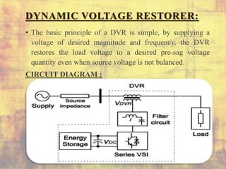
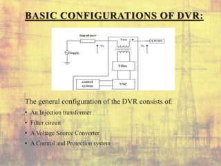
UNDER THE GUIDNESS OF
Mr. J.VasanthKumar., M.Tech Asst.professor
Department of EEE
BY USING BESS THE COMPENSATION OF VOLTAGE
SAG&SWELL CAN BE CONTROLLED BY DVR
PRESENTED BY
K. Krishna reddy 14C25A0219
D. Swapna 14C25A0206
G. Ramu 13C21A0209
G. Rajashekar 13C21A0208
INTRODUCTION:
• POWER QUALITY problems in the present-day
distribution systems are due to the increased use of
sensitive and critical equipment pieces .
• Series-connected compensators known as dynamic voltage
restorers (DVRs)
DYNAMIC VOLTAGE RESTORER:
• The basic principle of a DVR is simple, by supplying a
voltage of desired magnitude and frequency, the DVR
restores the load voltage to a desired pre-sag voltage
quantity even when source voltage is not balanced.
CIRCUIT DIAGRAM :
BASIC CONFIGURATIONS OF DVR:
The general configuration of the DVR consists of:
• An Injection transformer
• Filter circuit
• A Voltage Source Converter
• A Control and Protection system
VOLTAGE SAG:
• Description: A decrease of the normal voltage level
between 10% and 90% of the nominal RMS voltage at the
power frequency, for durations of 0.5 cycle to 1 minute.
.
Voltage sag Consequences:
• Malfunction of microprocessor-based control systems(PCs,
PLCs, etc.)
• Tripping of contactors and relays.
• Disconnection and loss of efficiency in rotating machines.
• Dimming of lighting system.
THREE PHASE SAG VOLTAGES:
VOLTAGE SWELL:
• Description: Swell can be defined as, “An increase to
between 80% and 180% in rms voltage or current at the
power frequency durations from 0.5 to 1 minute
Voltage swell Consequences:
• Data loss, flickering of lighting and screen.
• stoppage or damage of sensitive equipment if the voltage
values are too high.
• Production rates fluctuates.
• Variable speed drives close down to prevent damage.
THREE PHASE SWELL VOLTAGES:
CIRCUIT DIAGRAM:
DYNAMIC PERFORMANCE OF DVR WITH IN-PHASE INJECTION DURING
VOLTAGE SAG AND SWELL APPLIED TO CRITICAL LOAD
ADVANTAGES:
• It is less expensive
• Small in size
• Better power effective device as compare to other links
UPS,SMES,DSTATCOM.
• Fast response
• Less Maintenances
APPLICATIONS:
• Transmission
• Distribution
• Non-Linear loads
• Communication Network
• Process industries
• Precise manufacturing process
LIMITATIONS:
• DVR, the energy storage size of DVR is kept low.
• DVR has a limited current conduction and voltage
injection capability.
FUTURE SCOPE:
• Study and control of power quality issues for deregulated
power system.
• Soft computing techniques developed can be further used
in various fields of power system like – power system
dynamics & stability, smart grid, power system state
estimation, economic dispatch and optimal power flow.
CONCLUSION:
 The operation of a DVR has been demonstrated with a
new control technique using various voltage injection
schemes. A comparison of the performance of the DVR
with different schemes has been performed with a reduced-
rating VSC, including a capacitor-supported DVR. The
SRF theory has been used for estimating the reference
DVR voltages. It is concluded that the voltage injection in-
phase with the PCC voltage results in minimum rating of
DVR but at the cost of an energy source at its dc bus.
REFERENCES:
• M. H. J. Bollen, Understanding Power Quality Problems—Voltage Sags
and Interruptions. New York, NY, USA: IEEE Press, 2000.
• A. Ghosh and G. Ledwich, Power Quality Enhancement Using Custom
Power Devices. London, U.K.: Kluwer, 2002.
• M. H. J. Bollen and I. Gu, Signal Processing of Power Quality
Disturbances. Hoboken, NJ, USA: Wiley-IEEE Press, 2006.
• IEEE Recommended Practices and Recommendations for Harmonics
Control in Electric Power Systems, IEEE Std. 519, 1992.
• M. Vilathgamuwa, R. Perera, S. Choi, and K. Tseng, “Control of energy
optimized dynamic voltage restorer,” in Proc. IEEE IECON, 1999, vol. 2,
pp. 873–878.
• J. G. Nielsen and F. Blaabjerg, “A detailed comparison of system
topologies for dynamic voltage restorers,” IEEE Trans. Ind. Appl., vol.
41, no. 5,pp. 1272–1280, Sep./Oct. 2005.
Control of dvr with a bess

Control of dvr with a bess

  • 1.
    UNDER THE GUIDNESSOF Mr. J.VasanthKumar., M.Tech Asst.professor Department of EEE BY USING BESS THE COMPENSATION OF VOLTAGE SAG&SWELL CAN BE CONTROLLED BY DVR PRESENTED BY K. Krishna reddy 14C25A0219 D. Swapna 14C25A0206 G. Ramu 13C21A0209 G. Rajashekar 13C21A0208
  • 2.
    INTRODUCTION: • POWER QUALITYproblems in the present-day distribution systems are due to the increased use of sensitive and critical equipment pieces . • Series-connected compensators known as dynamic voltage restorers (DVRs)
  • 3.
    DYNAMIC VOLTAGE RESTORER: •The basic principle of a DVR is simple, by supplying a voltage of desired magnitude and frequency, the DVR restores the load voltage to a desired pre-sag voltage quantity even when source voltage is not balanced. CIRCUIT DIAGRAM :
  • 4.
    BASIC CONFIGURATIONS OFDVR: The general configuration of the DVR consists of: • An Injection transformer • Filter circuit • A Voltage Source Converter • A Control and Protection system
  • 5.
    VOLTAGE SAG: • Description:A decrease of the normal voltage level between 10% and 90% of the nominal RMS voltage at the power frequency, for durations of 0.5 cycle to 1 minute.
  • 6.
    . Voltage sag Consequences: •Malfunction of microprocessor-based control systems(PCs, PLCs, etc.) • Tripping of contactors and relays. • Disconnection and loss of efficiency in rotating machines. • Dimming of lighting system.
  • 7.
    THREE PHASE SAGVOLTAGES:
  • 8.
    VOLTAGE SWELL: • Description:Swell can be defined as, “An increase to between 80% and 180% in rms voltage or current at the power frequency durations from 0.5 to 1 minute
  • 9.
    Voltage swell Consequences: •Data loss, flickering of lighting and screen. • stoppage or damage of sensitive equipment if the voltage values are too high. • Production rates fluctuates. • Variable speed drives close down to prevent damage.
  • 10.
  • 11.
  • 12.
    DYNAMIC PERFORMANCE OFDVR WITH IN-PHASE INJECTION DURING VOLTAGE SAG AND SWELL APPLIED TO CRITICAL LOAD
  • 13.
    ADVANTAGES: • It isless expensive • Small in size • Better power effective device as compare to other links UPS,SMES,DSTATCOM. • Fast response • Less Maintenances
  • 14.
    APPLICATIONS: • Transmission • Distribution •Non-Linear loads • Communication Network • Process industries • Precise manufacturing process
  • 15.
    LIMITATIONS: • DVR, theenergy storage size of DVR is kept low. • DVR has a limited current conduction and voltage injection capability.
  • 16.
    FUTURE SCOPE: • Studyand control of power quality issues for deregulated power system. • Soft computing techniques developed can be further used in various fields of power system like – power system dynamics & stability, smart grid, power system state estimation, economic dispatch and optimal power flow.
  • 17.
    CONCLUSION:  The operationof a DVR has been demonstrated with a new control technique using various voltage injection schemes. A comparison of the performance of the DVR with different schemes has been performed with a reduced- rating VSC, including a capacitor-supported DVR. The SRF theory has been used for estimating the reference DVR voltages. It is concluded that the voltage injection in- phase with the PCC voltage results in minimum rating of DVR but at the cost of an energy source at its dc bus.
  • 18.
    REFERENCES: • M. H.J. Bollen, Understanding Power Quality Problems—Voltage Sags and Interruptions. New York, NY, USA: IEEE Press, 2000. • A. Ghosh and G. Ledwich, Power Quality Enhancement Using Custom Power Devices. London, U.K.: Kluwer, 2002. • M. H. J. Bollen and I. Gu, Signal Processing of Power Quality Disturbances. Hoboken, NJ, USA: Wiley-IEEE Press, 2006. • IEEE Recommended Practices and Recommendations for Harmonics Control in Electric Power Systems, IEEE Std. 519, 1992. • M. Vilathgamuwa, R. Perera, S. Choi, and K. Tseng, “Control of energy optimized dynamic voltage restorer,” in Proc. IEEE IECON, 1999, vol. 2, pp. 873–878. • J. G. Nielsen and F. Blaabjerg, “A detailed comparison of system topologies for dynamic voltage restorers,” IEEE Trans. Ind. Appl., vol. 41, no. 5,pp. 1272–1280, Sep./Oct. 2005.