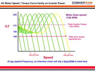
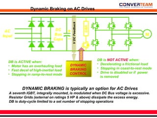
Drive and Motor Basics
Induction Motor Advantages
• Low cost (compared with DC)
• Wide availability
• Low maintenance - no brushes or commutator
• Rugged design - can be used in harsh environments
• Low inertia rotor designs
• High electrical efficiency
• Wide speed ranges
• No separately-powered field windings
• Good open-loop performance
AC MOTOR SIZE
Frame size is directly related to base RPM,
for a given Horsepower
Example: 15 HP motors of different base speeds
Base RPM
Frame Size
Torque
Amps
3600 (2-pole)
215
22.5 lb-ft
18.5
1800 (4-pole)
254
45 lb-ft
18.7
1200 (6-pole)
284
67.5 lb-ft
19.3
AC MOTOR FORMULA
120 x Frequency
# of Poles
SYNC RPM =
Example: 4-pole motor
SYNC RPM = 120 x 60 / 4poles = 1800 RPM
%SLIP =
SYNC RPM - FULL LOAD RPM
SYNC RPM
X 100
Example: 1750 RPM motor
% Slip = (1800 - 1750) / 1800 x 100 = 3% Slip
SYNCHRONOUS SPEED
MOTOR SLIP
VOLTS / HERTZ
V/Hz =
Motor Line Volts
Motor Frequency
Example: 460 V, 60 Hz motor
V/Hz = 460/60 = 7.66 V/Hz
VOLTS FREQUENCY V/Hz
460 60 7.66
345 45 7.66
230 30 7.66
115 15 7.66
7.66 1 7.66
Elements of an Induction Motor: The Stator
Stator Core
Lamination stack
of notched steel
plates
Elements of an Induction Motor: The Stator (4-pole)
t
The stator induces magnetic lines of
flux across the air gap, into the rotor
Rotating
magnetic field
Elements of an Induction Motor: The Rotor
Laminations of
high-silicon
content steel
Cast aluminum
rotor bars
Cast aluminum
end rings
Low-eddy current loss
magnetic medium
Electrically joins rotor
bars at both motor ends
Carry induced current
(skewed bars shown)
No direct electrical connections are made to the rotor. All forces are
magnetically induced by the stator, via the air gap.
Rotor Bar Current
Typical AC Induction Motor Speed / Torque Curve
“Across-the-line” operation @ 60 Hz, NEMA ‘B’ motor
Full load operating point (100%
current & torque)
1750 RPM (nameplate)
Breakdown point: Maximum
torque motor can produce
before locking rotor
Synchronous “no-load” speed
1800 RPM
(50 rpm)
100
175
225
Starting Torque
Pull-Up Torque
150
%T
Speed
LO
AD
SLIP
Speed
AC Motor Speed / Torque Curve family on Inverter Power
Slip (50 rpm)
100
175
225
150
%T
Slip (50 rpm)
100% load torque
operating line
Motor base speed:
1750 RPM
At any applied Frequency, an induction motor will slip a fixed RPM at rated load.
Peak Inverter Torque
(150 -200%)
Induction Motor Equivalent Circuit
Stator Rotor
Air
Gap
R1 XLR
XM
XR
RLOAD = R2 / Slip*
Although there is no physical connection between rotor and stator, the
induced field causes the motor model to behave as if there is.
Stator
Resistance
Leakage
Reactance
Magnetizing
Reactance
Rotor
Reactance
*(R2 is rotor bar resistance)
V
Motor Current Vectors
Stator Rotor
Air
Gap
R1
XLR
XM
XR
RLOAD
Stator
Resistance
Leakage
Reactance
Rotor
Reactance
Total Current
Magnetizing
Current
Torque
Current
Magnetizing
Current
Torque-Producing Current
Total Current Total Current is the Vector sum of
Magnetizing and Torque-producing
current, which are at a right angle
to each other.
Motor Current Vectors
Magnetizing
Current
Torque-Producing Current
Total Current
Magnetizing
Current
Torque-
Producing
Current
Total
Current
Magnetizing
Current
Torque-Producing Current
Total Current
LIGHT
LOAD
MEDIUM
LOAD
&
HEAVY
LOAD
• High % of total current is “magnetizing” current
• Magnetizing current is reactive (low p.f.)
• Measured (total) motor current is not a good
indicator of load level.
• Most of total current is
torque-producing
• Motors run at high
power factor
• Total motor current is
proportional to load level.
460
100
V
60
Hz
Hz
60 120
120
HORSEPOW
ER
Constant Horsepower
Constant Voltage
% T
& HP
Constant Torque
50
“Field Weakened Range”
Reduced Torque
Motor Operation above Base Speed
Torque  V/Hz
Frequency increases
above base speed, but
voltage levels off.
The result is increased
speed with weakened
torque, or constant HP
operation.
Above 2:1 , motor
torque drops sharply
& operation is not
recommended.
Typical AC Induction Motor Current & Torque Curves
“Across-the-line” operation @ 60 Hz, NEMA ‘B’ motor
100
175
225
150
% T
Speed
% I
650
400
Linear range: 40-150% load
(operating range in which current is
proportional to torque)
Starting (inrush) current
Breakdown current:
maximum level when motor
locks rotor (stalls)
AC DRIVE BASICS
All AC Drives convert “fixed” voltage and frequency into “variable” voltage
and frequency, to run 3-phase induction motors.
LINE INPUT
MOTOR
OUTPUT
Types of AC Drives
In today’s marketplace, there are
3 basic AC Drive categories:
• Open loop “Volts / Hz” Drives
• Open loop “Sensorless Vector”
Drives
• Closed loop “Flux Vector” Drives
All are Pulse-Width-Modulated (PWM)
Some manufacturers offer 2-in-1 & 3-in-
1 Drives, combining these attributes.
V/Hz
SENSOR-
LESS
VECTOR
FLUX
VECTOR
“Volts / Hz” Drives
V
o
l
t
s
230
460
30 60 Hz
RPM*
900 1800
(Base)
0
• Motor voltage is varied linearly with frequency
• No compensation for motor & load dynamics
• Poor shock load response characteristics
*( 4-pole motor)
Motor Nameplate V/Hz
Torque Boost
AC Motor Torque & HP vs. Speed
50
100
30 60
900 1800
0
T & HP
%
Torque
HP
Hz
RPM
• Motor Torque is constant to base speed
• HP varies proportionally to speed
AC
Input
DC
Bus
Caps
AC to DC
Rectifier
Pulse-Width-Modulated Inverter
DC Filter
DC to AC
Inverter
IGBTs
AC
Output
All PWM inverters (V/Hz, Vector & Sensorless Vector) share similar power circuit
topologies.
AC is converted to DC, filtered, and inverted to variable frequency, variable
voltage AC.
M
PWM Power Circuit:AC to DC Converter Section
AC
Input
DC
Bus
Caps
AC to DC
Rectifier
DC Filter
+
-
Input Reactor
(option)
DC Reactor
The AC input is rectified and filtered into fixed-voltage DC
• Certain manufacturer’s units contain an integral DC reactor (choke)
as part of the DC filter.
• Adding an external AC input reactor will yield similar benefits.
• Both reduce harmonics, smooth and lower peak current.
PWM Power Circuit:DC to AC Inverter Section
DC Filter
DC to AC
Inverter
IGBTs
AC
Output
M
An IGBT (Insulated Gate Bipolar Transistor) is a high-speed power semiconductor switch.
IGBTs are pulse-width modulated with a specific firing pattern, chopping the DC voltage into 3-
phase AC voltage of the proper frequency and voltage.
The resulting motor current is near-sinusoidal, due to motor inductance.
Imotor
Vu-v
U
V
W
IGBT Firing
Signals
+
-
IGBT Firing
Signals
PWM
microprocessor
controller
Operator
Interface
V
f
Basic V/HZ Control Circuit: Input, Feedback and Control
Signals
Motor current &
voltage feedback
DC Bus current &
voltage feedback
Speed reference
IGBT Gating
Signals
PWM
microprocessor
controller with
Vector algorithm
Man-
machine
Interface
Flux Vector Control Elements: Input,Feedback, Control Signals
Encoder Feedback
Motor current &
voltage feedback
DC Bus voltage
feedback
Speed and / or
Torque reference
Variable Torque Applications: Centrifugal Pumps & Fans
• Load varies with the square of
the speed
• HP varies with the cube of the
speed
• Ideally suited for AC Drives
• Energy savings benefits: only
50% power required at 80% flow
• AC Drives replace inefficient
dampers, guide vanes and valves
Speed
Flow
or Volum
e
Torque
Horsepower
Flow,
Torque
&
Horsepower
100%
100%
T = K x (RPM)2
HP = K x (RPM)3
80%
50%
80%
4-Quadrant Operation of AC Motors on Inverter Power
FORWARD
MOTORING
REVERSE
MOTORING
REVERSE
REGENERATING
FORWARD
REGENERATING
+ RPM
- RPM
Clockwise
TORQUE
Counter-
Clockwise
TORQUE
WEIGHT
PULL
ROTATION
Conditions for Regenerating on an AC Motor
AC Motors regenerate when pulled faster than their
sync speed at the applied frequency.
At 60 Hz, if a motor is pulled faster than 1800 RPM*,
the motor will behave as an induction generator.
Regeneration conditions:
• Overhauling loads
• Fast deceleration of high inertial loads
• Stopping on a timed-ramp
• Cyclic loads or eccentric shaft loading
* 1750 RPM base
speed at 60 Hz
AC Drive Regeneration
AC
Input
DC
Bus
Caps
IGBTs M
ONE - WAY TWO - WAY
Energy Flow:
+
_
• Current flows back into the DC bus, via the IGBT switching & back diodes.
• AC Drive front-end rectifier is unidirectional; energy cannot flow back into the AC
line.
• Some returned energy is dissipated in losses in the capacitors, switches, and motor
windings (10-15%).
• Excessive regeneration can cause problems, such as DC Bus Overvoltage.
Dynamic Braking on AC Drives
AC
Input
DC
Bus
Caps
M
+
_
DBR
DYNAMIC
BRAKING
CONTROL
V
DC
Feedback
SIGNAL
DYNAMIC BRAKING is typically an option for AC Drives
A seventh IGBT, integrally mounted, is modulated when DC Bus voltage is excessive.
Resistor Grids (external on ratings 5 HP & above) dissipate the excess energy.
DB is duty-cycle limited to a set number of stopping operations
DB is ACTIVE when:
• Motor has an overhauling load
• Fast decel of high-inertial load
• Stopping in ramp-to-rest mode
DB is NOT ACTIVE when:
• Decelerating a frictional load
• Stopping in coast-to-rest mode
• Drive is disabled or if power
is removed
Dynamic Braking on AC Drives:
Application Considerations
DB is not failsafe: if the drive faults or power is removed, DB will not
function.
DB only operates when the drive is running: in coast-rest or stand-by,
DB is inactive.
DB should not be used in EMERGENCY STOPPING: the drive will
continue on a timed ramp, producing torque the entire time.
DB is suitable for intermittent operation only: other regenerative
solutions exist for long-term overhauling loads
AC
DRIVE
AC
DRIVE
AC
DRIVE
AC Drives on a Common DC Bus: Typical Connection Diagram
THERMAL- MAG
BREAKER
INPUT LINE
REACTOR
SEMICONDUCTOR
FUSES
INTERLOCKED
DC CONTACTOR
DC DRIVE BASICS
DC Drives convert AC line voltage into variable DC voltage with an SCR
phase-controlled bridge rectifier, to power the DC motor ARMATURE. A
separate field supply provides the motor with DC FIELD excitation.
LINE INPUT MOTOR OUTPUT
Armature
Field
A1
A2
F1
F2
Power Switches
The SCR: (Silicon Controlled Rectifier)
a.k.a. - “Thyristor”
ANODE CATHODE
GATE
• Extremely robust solid-state switch / 40+ year proven track record
• Key element in DC Drive power circuit
• Simple pulse gating turns on current flow
• Device has self-turn-off when reverse biased
• Stud-mount, hockey-puck and encapsulated 2-, 4- and 6-pack types
available in certain sizes and ratings.
TRIGGER
-
+
Application Issues: AC Line Notching
on DC Drives
AC
Input
Commutation notches are caused by the
transfer of current from one SCR to another.
The notches can cause misfiring on drives
common to the same power line.
V ph-ph
Solution: Installation of a small (25-50 uH range), 3-phase reactor on each
DC controller will prevent cross-talk and other related problems.
Elements of a DC Drive:Non-regenerative type
AC
Input
SCR Firing
Signals
Microprocessor
controller
Operator
Interface
S
E
Q
REF
LO
CA
L
AC MOTOR DRIVE
0.75
KW
200 V v 1.3
HEALTH
L
R
PROG
E
M
RUN
F
W
D
RE
V
JOG
RESET
STOP
RESET
Speed or Torque
Reference
Field
Control
Signals
A1
A2
F1
F2
Tachometer
Feedback
(closed-loop)
Motor voltage
feedback
Line current
feedback
Elements of a DC Drive:Regenerative type
AC
Input
SCR Firing Signals
Microprocessor
controller
Operator
Interface
S
E
Q
REF
LO
CA
L
AC MOTOR DRIVE
0.75
KW
200 V v 1.3
HEALTH
L
R
PROG
E
M
RUN
F
W
D
RE
V
JOG
RESET
STOP
RESET
Speed or Torque
Reference
Field
Control
Signals
A1
A2
F1
F2
Tachometer
Feedback
(closed-loop)
Motor voltage
feedback
FWD/MOT REGEN/REV
F
F F F
F F R
R
R
R
R
R
Line current
feedback

Motor& Drive Basics working presentation

  • 1.
    Drive and MotorBasics Drive and Motor Basics
  • 2.
    Induction Motor Advantages •Low cost (compared with DC) • Wide availability • Low maintenance - no brushes or commutator • Rugged design - can be used in harsh environments • Low inertia rotor designs • High electrical efficiency • Wide speed ranges • No separately-powered field windings • Good open-loop performance
  • 3.
    AC MOTOR SIZE Framesize is directly related to base RPM, for a given Horsepower Example: 15 HP motors of different base speeds Base RPM Frame Size Torque Amps 3600 (2-pole) 215 22.5 lb-ft 18.5 1800 (4-pole) 254 45 lb-ft 18.7 1200 (6-pole) 284 67.5 lb-ft 19.3
  • 4.
    AC MOTOR FORMULA 120x Frequency # of Poles SYNC RPM = Example: 4-pole motor SYNC RPM = 120 x 60 / 4poles = 1800 RPM %SLIP = SYNC RPM - FULL LOAD RPM SYNC RPM X 100 Example: 1750 RPM motor % Slip = (1800 - 1750) / 1800 x 100 = 3% Slip SYNCHRONOUS SPEED MOTOR SLIP VOLTS / HERTZ V/Hz = Motor Line Volts Motor Frequency Example: 460 V, 60 Hz motor V/Hz = 460/60 = 7.66 V/Hz VOLTS FREQUENCY V/Hz 460 60 7.66 345 45 7.66 230 30 7.66 115 15 7.66 7.66 1 7.66
  • 5.
    Elements of anInduction Motor: The Stator Stator Core Lamination stack of notched steel plates
  • 6.
    Elements of anInduction Motor: The Stator (4-pole) t The stator induces magnetic lines of flux across the air gap, into the rotor Rotating magnetic field
  • 7.
    Elements of anInduction Motor: The Rotor Laminations of high-silicon content steel Cast aluminum rotor bars Cast aluminum end rings Low-eddy current loss magnetic medium Electrically joins rotor bars at both motor ends Carry induced current (skewed bars shown) No direct electrical connections are made to the rotor. All forces are magnetically induced by the stator, via the air gap. Rotor Bar Current
  • 8.
    Typical AC InductionMotor Speed / Torque Curve “Across-the-line” operation @ 60 Hz, NEMA ‘B’ motor Full load operating point (100% current & torque) 1750 RPM (nameplate) Breakdown point: Maximum torque motor can produce before locking rotor Synchronous “no-load” speed 1800 RPM (50 rpm) 100 175 225 Starting Torque Pull-Up Torque 150 %T Speed LO AD SLIP
  • 9.
    Speed AC Motor Speed/ Torque Curve family on Inverter Power Slip (50 rpm) 100 175 225 150 %T Slip (50 rpm) 100% load torque operating line Motor base speed: 1750 RPM At any applied Frequency, an induction motor will slip a fixed RPM at rated load. Peak Inverter Torque (150 -200%)
  • 10.
    Induction Motor EquivalentCircuit Stator Rotor Air Gap R1 XLR XM XR RLOAD = R2 / Slip* Although there is no physical connection between rotor and stator, the induced field causes the motor model to behave as if there is. Stator Resistance Leakage Reactance Magnetizing Reactance Rotor Reactance *(R2 is rotor bar resistance) V
  • 11.
    Motor Current Vectors StatorRotor Air Gap R1 XLR XM XR RLOAD Stator Resistance Leakage Reactance Rotor Reactance Total Current Magnetizing Current Torque Current Magnetizing Current Torque-Producing Current Total Current Total Current is the Vector sum of Magnetizing and Torque-producing current, which are at a right angle to each other.
  • 12.
    Motor Current Vectors Magnetizing Current Torque-ProducingCurrent Total Current Magnetizing Current Torque- Producing Current Total Current Magnetizing Current Torque-Producing Current Total Current LIGHT LOAD MEDIUM LOAD & HEAVY LOAD • High % of total current is “magnetizing” current • Magnetizing current is reactive (low p.f.) • Measured (total) motor current is not a good indicator of load level. • Most of total current is torque-producing • Motors run at high power factor • Total motor current is proportional to load level.
  • 13.
    460 100 V 60 Hz Hz 60 120 120 HORSEPOW ER Constant Horsepower ConstantVoltage % T & HP Constant Torque 50 “Field Weakened Range” Reduced Torque Motor Operation above Base Speed Torque  V/Hz Frequency increases above base speed, but voltage levels off. The result is increased speed with weakened torque, or constant HP operation. Above 2:1 , motor torque drops sharply & operation is not recommended.
  • 14.
    Typical AC InductionMotor Current & Torque Curves “Across-the-line” operation @ 60 Hz, NEMA ‘B’ motor 100 175 225 150 % T Speed % I 650 400 Linear range: 40-150% load (operating range in which current is proportional to torque) Starting (inrush) current Breakdown current: maximum level when motor locks rotor (stalls)
  • 15.
    AC DRIVE BASICS AllAC Drives convert “fixed” voltage and frequency into “variable” voltage and frequency, to run 3-phase induction motors. LINE INPUT MOTOR OUTPUT
  • 16.
    Types of ACDrives In today’s marketplace, there are 3 basic AC Drive categories: • Open loop “Volts / Hz” Drives • Open loop “Sensorless Vector” Drives • Closed loop “Flux Vector” Drives All are Pulse-Width-Modulated (PWM) Some manufacturers offer 2-in-1 & 3-in- 1 Drives, combining these attributes. V/Hz SENSOR- LESS VECTOR FLUX VECTOR
  • 17.
    “Volts / Hz”Drives V o l t s 230 460 30 60 Hz RPM* 900 1800 (Base) 0 • Motor voltage is varied linearly with frequency • No compensation for motor & load dynamics • Poor shock load response characteristics *( 4-pole motor) Motor Nameplate V/Hz Torque Boost
  • 18.
    AC Motor Torque& HP vs. Speed 50 100 30 60 900 1800 0 T & HP % Torque HP Hz RPM • Motor Torque is constant to base speed • HP varies proportionally to speed
  • 19.
    AC Input DC Bus Caps AC to DC Rectifier Pulse-Width-ModulatedInverter DC Filter DC to AC Inverter IGBTs AC Output All PWM inverters (V/Hz, Vector & Sensorless Vector) share similar power circuit topologies. AC is converted to DC, filtered, and inverted to variable frequency, variable voltage AC. M
  • 20.
    PWM Power Circuit:ACto DC Converter Section AC Input DC Bus Caps AC to DC Rectifier DC Filter + - Input Reactor (option) DC Reactor The AC input is rectified and filtered into fixed-voltage DC • Certain manufacturer’s units contain an integral DC reactor (choke) as part of the DC filter. • Adding an external AC input reactor will yield similar benefits. • Both reduce harmonics, smooth and lower peak current.
  • 21.
    PWM Power Circuit:DCto AC Inverter Section DC Filter DC to AC Inverter IGBTs AC Output M An IGBT (Insulated Gate Bipolar Transistor) is a high-speed power semiconductor switch. IGBTs are pulse-width modulated with a specific firing pattern, chopping the DC voltage into 3- phase AC voltage of the proper frequency and voltage. The resulting motor current is near-sinusoidal, due to motor inductance. Imotor Vu-v U V W IGBT Firing Signals + -
  • 22.
    IGBT Firing Signals PWM microprocessor controller Operator Interface V f Basic V/HZControl Circuit: Input, Feedback and Control Signals Motor current & voltage feedback DC Bus current & voltage feedback Speed reference
  • 23.
    IGBT Gating Signals PWM microprocessor controller with Vectoralgorithm Man- machine Interface Flux Vector Control Elements: Input,Feedback, Control Signals Encoder Feedback Motor current & voltage feedback DC Bus voltage feedback Speed and / or Torque reference
  • 24.
    Variable Torque Applications:Centrifugal Pumps & Fans • Load varies with the square of the speed • HP varies with the cube of the speed • Ideally suited for AC Drives • Energy savings benefits: only 50% power required at 80% flow • AC Drives replace inefficient dampers, guide vanes and valves Speed Flow or Volum e Torque Horsepower Flow, Torque & Horsepower 100% 100% T = K x (RPM)2 HP = K x (RPM)3 80% 50% 80%
  • 25.
    4-Quadrant Operation ofAC Motors on Inverter Power FORWARD MOTORING REVERSE MOTORING REVERSE REGENERATING FORWARD REGENERATING + RPM - RPM Clockwise TORQUE Counter- Clockwise TORQUE
  • 26.
    WEIGHT PULL ROTATION Conditions for Regeneratingon an AC Motor AC Motors regenerate when pulled faster than their sync speed at the applied frequency. At 60 Hz, if a motor is pulled faster than 1800 RPM*, the motor will behave as an induction generator. Regeneration conditions: • Overhauling loads • Fast deceleration of high inertial loads • Stopping on a timed-ramp • Cyclic loads or eccentric shaft loading * 1750 RPM base speed at 60 Hz
  • 27.
    AC Drive Regeneration AC Input DC Bus Caps IGBTsM ONE - WAY TWO - WAY Energy Flow: + _ • Current flows back into the DC bus, via the IGBT switching & back diodes. • AC Drive front-end rectifier is unidirectional; energy cannot flow back into the AC line. • Some returned energy is dissipated in losses in the capacitors, switches, and motor windings (10-15%). • Excessive regeneration can cause problems, such as DC Bus Overvoltage.
  • 28.
    Dynamic Braking onAC Drives AC Input DC Bus Caps M + _ DBR DYNAMIC BRAKING CONTROL V DC Feedback SIGNAL DYNAMIC BRAKING is typically an option for AC Drives A seventh IGBT, integrally mounted, is modulated when DC Bus voltage is excessive. Resistor Grids (external on ratings 5 HP & above) dissipate the excess energy. DB is duty-cycle limited to a set number of stopping operations DB is ACTIVE when: • Motor has an overhauling load • Fast decel of high-inertial load • Stopping in ramp-to-rest mode DB is NOT ACTIVE when: • Decelerating a frictional load • Stopping in coast-to-rest mode • Drive is disabled or if power is removed
  • 29.
    Dynamic Braking onAC Drives: Application Considerations DB is not failsafe: if the drive faults or power is removed, DB will not function. DB only operates when the drive is running: in coast-rest or stand-by, DB is inactive. DB should not be used in EMERGENCY STOPPING: the drive will continue on a timed ramp, producing torque the entire time. DB is suitable for intermittent operation only: other regenerative solutions exist for long-term overhauling loads
  • 30.
    AC DRIVE AC DRIVE AC DRIVE AC Drives ona Common DC Bus: Typical Connection Diagram THERMAL- MAG BREAKER INPUT LINE REACTOR SEMICONDUCTOR FUSES INTERLOCKED DC CONTACTOR
  • 31.
    DC DRIVE BASICS DCDrives convert AC line voltage into variable DC voltage with an SCR phase-controlled bridge rectifier, to power the DC motor ARMATURE. A separate field supply provides the motor with DC FIELD excitation. LINE INPUT MOTOR OUTPUT Armature Field A1 A2 F1 F2
  • 32.
    Power Switches The SCR:(Silicon Controlled Rectifier) a.k.a. - “Thyristor” ANODE CATHODE GATE • Extremely robust solid-state switch / 40+ year proven track record • Key element in DC Drive power circuit • Simple pulse gating turns on current flow • Device has self-turn-off when reverse biased • Stud-mount, hockey-puck and encapsulated 2-, 4- and 6-pack types available in certain sizes and ratings. TRIGGER - +
  • 33.
    Application Issues: ACLine Notching on DC Drives AC Input Commutation notches are caused by the transfer of current from one SCR to another. The notches can cause misfiring on drives common to the same power line. V ph-ph Solution: Installation of a small (25-50 uH range), 3-phase reactor on each DC controller will prevent cross-talk and other related problems.
  • 34.
    Elements of aDC Drive:Non-regenerative type AC Input SCR Firing Signals Microprocessor controller Operator Interface S E Q REF LO CA L AC MOTOR DRIVE 0.75 KW 200 V v 1.3 HEALTH L R PROG E M RUN F W D RE V JOG RESET STOP RESET Speed or Torque Reference Field Control Signals A1 A2 F1 F2 Tachometer Feedback (closed-loop) Motor voltage feedback Line current feedback
  • 35.
    Elements of aDC Drive:Regenerative type AC Input SCR Firing Signals Microprocessor controller Operator Interface S E Q REF LO CA L AC MOTOR DRIVE 0.75 KW 200 V v 1.3 HEALTH L R PROG E M RUN F W D RE V JOG RESET STOP RESET Speed or Torque Reference Field Control Signals A1 A2 F1 F2 Tachometer Feedback (closed-loop) Motor voltage feedback FWD/MOT REGEN/REV F F F F F F R R R R R R Line current feedback