Downloaded 125 times

![5
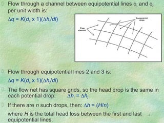
Substitution yields: ∆q = K(dm/dl)(H/n)
This equation is for one flow channel. If there are m such
channels in the net, then total flow per unit width is:
q = (m/n)K(dm/dl)H
Since the flow net is drawn with squares, then dm ≈ dl, and:
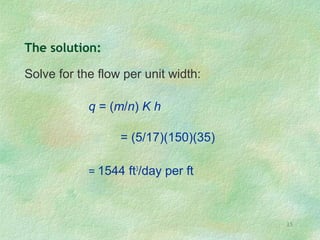
q = (m/n)KH [L2
T-1
]
where:
q = rate of flow or seepage per unit width
m= number of flow channels
n= number of equipotential drops
h = total head loss in flow system
K = hydraulic conductivity](https://image.slidesharecdn.com/4-flownets-170724070429/85/Drainage-Engineering-Flow-Nets-5-320.jpg)
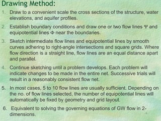
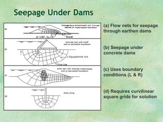
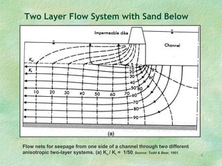
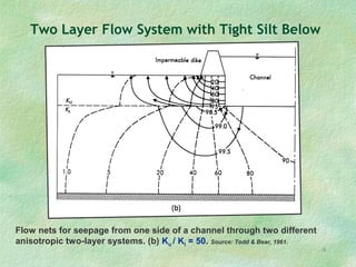

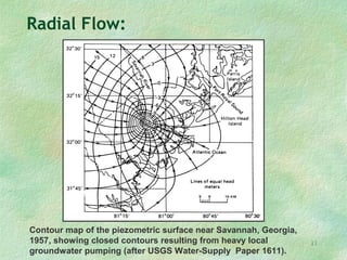
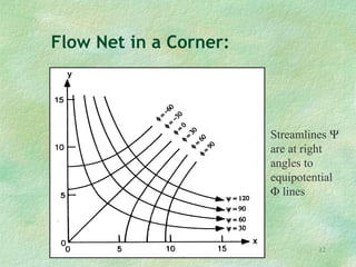
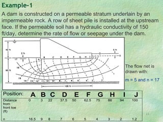
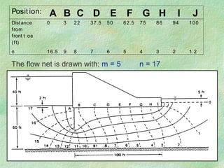
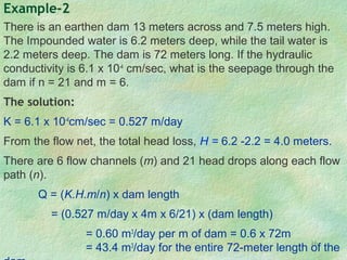

Flow net theory describes the graphical representation of groundwater flow through porous media. Flow nets show streamlines perpendicular to equipotential lines forming curvilinear square grids. They can model flow under dams, through layered soils, and with different boundary conditions. Examples calculate seepage rates from flow net parameters like hydraulic conductivity, head loss, number of streamlines and equipotential lines.


![Geotechnical Engineering-I [Lec #27: Flow Nets]](https://cdn.slidesharecdn.com/ss_thumbnails/27-180924141458-thumbnail.jpg?width=640&height=640&fit=bounds)


![Geotechnical Engineering-I [Lec #27A: Flow Calculation From Flow Nets]](https://cdn.slidesharecdn.com/ss_thumbnails/27-180924141501-thumbnail.jpg?width=640&height=640&fit=bounds)


