Download as PDF, PPTX

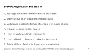
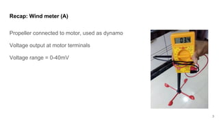
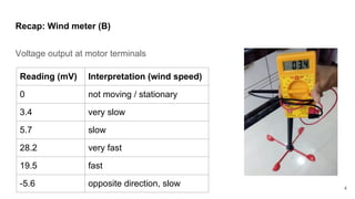
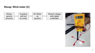
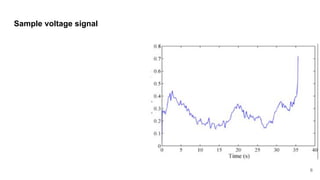
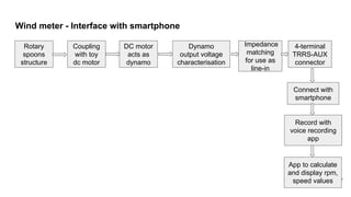
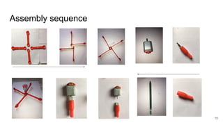
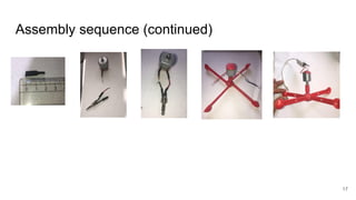
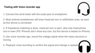

This document provides instructions for extending a simple wind meter to an Internet of Things device by interfacing it with a smartphone. It discusses: 1) Building the mechanical structure of a propeller-based wind meter and coupling it to a DC motor to generate a voltage output proportional to wind speed. 2) Adding electronic components like a resistor and wiring to match the motor's impedance to a smartphone audio input. 3) Creating a mobile app to record the voltage signal from the wind meter and convert the readings to values like rotations per minute and wind speed.