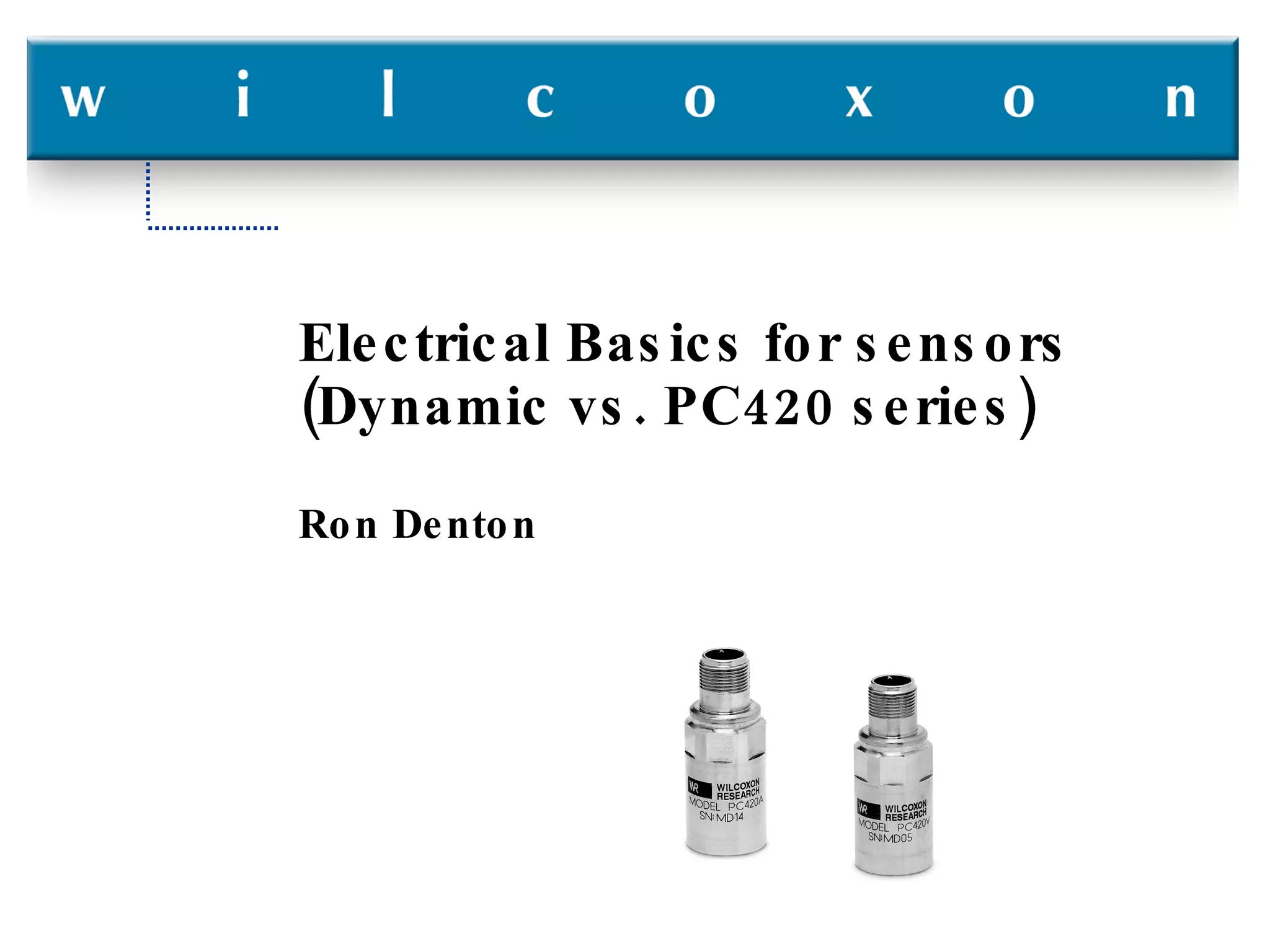
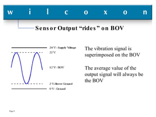
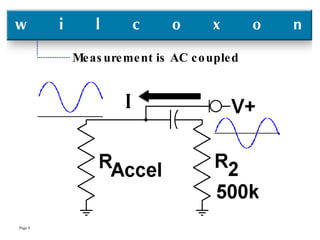
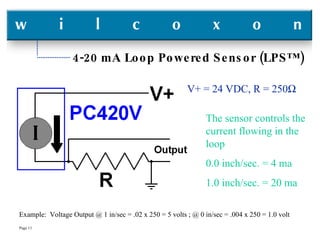
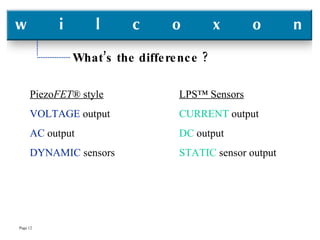
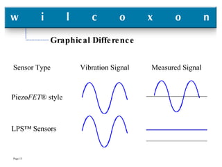
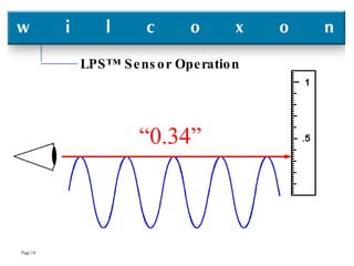
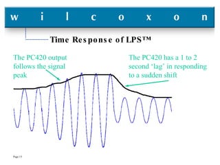
Electrical Basics for sensors (Dynamic vs. PC420 series) Ron Denton
Electrical Basics for sensors (Dynamic vs. PC420 series) What is Ohm’s law ? How does a “constant current/voltage modulated” sensor work ? How does a “Loop Powered Sensor” work ? What’s the difference ?
Ohm’s Law Mathematical expressions of Ohm’s law: V=I*R  I=V/R  R=V/I where: V is Voltage, I is Current, and R is Resistance Each of these equations is identical, they are simply re-arranged to solve for one particular variable.
Ohm’s Law - Units and Symbols Voltage:  Expressed in Volts or V, and possibly modified by (Alternating Current) as VAC or  (Direct Current) as VDC Current:  Expressed in Amperes, Amps or A Resistance: Expressed in Ohms or     Unit multipliers: k = kilo = 1,000 ; M = Mega = 1,000,000 m = milli = 1/1,000 ; p = pico = 1/1,000,000 Examples: 100 millivolts = 0.1 volts ; 20 milliamps = 0.02 amps  1.5 kVDC = 1,500 Volts DC
Ohm’s Law - Circuit example V = I * R I = V / R R = V / I Example 1: R = 250   , I = 20 mA ; find V  V = 0.020 x 250 = 5.0 volts  Example 2: V = 1.0 volt, R = 250    ; find I  I = 1.0 / 250 = 0.004
Voltage Modulated Sensors A.k.a.- Piezo FET ™ , ICP™, and others
Sensor Connection Circuit V = Sensor BOV Constant Current Diode (CCD) Typically 4 mA 18 - 30 VDC
Sensor Output “rides” on BOV The vibration signal is superimposed on the BOV The average value of the output signal will always be the BOV
Measurement is AC coupled
Loop Powered Sensor What is a loop powered sensor ? How does it work anyway ? Is that different from the “current modulated” power that Wilcoxon uses on sensors now ? Why would anyone want one ? Who usually buys this kind of sensor ?
4-20 mA Loop Powered Sensor (LPS™) The sensor controls the current flowing in the loop 0.0 inch/sec. = 4 ma 1.0 inch/sec. = 20 ma Example:  Voltage Output @ 1 in/sec = .02 x 250 = 5 volts ; @ 0 in/sec = .004 x 250 = 1.0 volt V+ = 24 VDC, R = 250 
What’s the difference ? Piezo FET ® style VOLTAGE  output AC  output DYNAMIC  sensors LPS™ Sensors CURRENT  output DC  output STATIC  sensor output
Graphical Difference Piezo FET ® style LPS™ Sensors Sensor Type  Vibration Signal  Measured Signal
LPS™ Sensor Operation “ 0.34”
Time Response of LPS™ The PC420 output follows the signal peak The PC420 has a 1 to 2 second ‘lag’ in responding to a sudden shift
Frequency Response of PC420’s If PC420 series is DC output, why do they have a frequency response specification ? All sensors have frequency limitations imposed by electrical and mechanical design parameters The PC420 series is no different The “DC” output is derived from the basic accelerometer That output signal is “converted” to DC by averaging
Why would anyone want an LPS™ ? Connecting an LPS™ to a plant’s Distributed Control System (DCS) or a Programmable Logic Controller (PLC), allows the overall vibration of machinery to be monitored  more frequently  than a plant’s predictive vibration program. Trending this overall vibration can  spot trouble faster  than a plant’s predictive vibration program. This is very  valuable  for critical machinery. The data can be made available to  machine operators .
Who usually buys this kind of sensor ? Initially, the predictive vibration group would have to be involved in the selection of a PC420 sensor. Usually the sensors are purchased by the Instrument & Electronic ( I&E ) group. The money usually comes from the production budget, not the maintenance budget. There is always more money available from the production budget than from the maintenance budget.
Summary “ Dynamic” Sensors Constant Current Supply Voltage Output AC Output Bought by Maintenance (usually the vibration group) LPS™ Sensors DCS/PLC Voltage Supply Current Output DC Output Bought  by I&E (usually under the production department)

Wilcoxon - Accelerometer Electronic Basics

  • 1.
    Electrical Basics forsensors (Dynamic vs. PC420 series) Ron Denton
  • 2.
    Electrical Basics forsensors (Dynamic vs. PC420 series) What is Ohm’s law ? How does a “constant current/voltage modulated” sensor work ? How does a “Loop Powered Sensor” work ? What’s the difference ?
  • 3.
    Ohm’s Law Mathematicalexpressions of Ohm’s law: V=I*R I=V/R R=V/I where: V is Voltage, I is Current, and R is Resistance Each of these equations is identical, they are simply re-arranged to solve for one particular variable.
  • 4.
    Ohm’s Law -Units and Symbols Voltage: Expressed in Volts or V, and possibly modified by (Alternating Current) as VAC or (Direct Current) as VDC Current: Expressed in Amperes, Amps or A Resistance: Expressed in Ohms or  Unit multipliers: k = kilo = 1,000 ; M = Mega = 1,000,000 m = milli = 1/1,000 ; p = pico = 1/1,000,000 Examples: 100 millivolts = 0.1 volts ; 20 milliamps = 0.02 amps 1.5 kVDC = 1,500 Volts DC
  • 5.
    Ohm’s Law -Circuit example V = I * R I = V / R R = V / I Example 1: R = 250  , I = 20 mA ; find V V = 0.020 x 250 = 5.0 volts Example 2: V = 1.0 volt, R = 250  ; find I I = 1.0 / 250 = 0.004
  • 6.
    Voltage Modulated SensorsA.k.a.- Piezo FET ™ , ICP™, and others
  • 7.
    Sensor Connection CircuitV = Sensor BOV Constant Current Diode (CCD) Typically 4 mA 18 - 30 VDC
  • 8.
    Sensor Output “rides”on BOV The vibration signal is superimposed on the BOV The average value of the output signal will always be the BOV
  • 9.
  • 10.
    Loop Powered SensorWhat is a loop powered sensor ? How does it work anyway ? Is that different from the “current modulated” power that Wilcoxon uses on sensors now ? Why would anyone want one ? Who usually buys this kind of sensor ?
  • 11.
    4-20 mA LoopPowered Sensor (LPS™) The sensor controls the current flowing in the loop 0.0 inch/sec. = 4 ma 1.0 inch/sec. = 20 ma Example: Voltage Output @ 1 in/sec = .02 x 250 = 5 volts ; @ 0 in/sec = .004 x 250 = 1.0 volt V+ = 24 VDC, R = 250 
  • 12.
    What’s the difference? Piezo FET ® style VOLTAGE output AC output DYNAMIC sensors LPS™ Sensors CURRENT output DC output STATIC sensor output
  • 13.
    Graphical Difference PiezoFET ® style LPS™ Sensors Sensor Type Vibration Signal Measured Signal
  • 14.
  • 15.
    Time Response ofLPS™ The PC420 output follows the signal peak The PC420 has a 1 to 2 second ‘lag’ in responding to a sudden shift
  • 16.
    Frequency Response ofPC420’s If PC420 series is DC output, why do they have a frequency response specification ? All sensors have frequency limitations imposed by electrical and mechanical design parameters The PC420 series is no different The “DC” output is derived from the basic accelerometer That output signal is “converted” to DC by averaging
  • 17.
    Why would anyonewant an LPS™ ? Connecting an LPS™ to a plant’s Distributed Control System (DCS) or a Programmable Logic Controller (PLC), allows the overall vibration of machinery to be monitored more frequently than a plant’s predictive vibration program. Trending this overall vibration can spot trouble faster than a plant’s predictive vibration program. This is very valuable for critical machinery. The data can be made available to machine operators .
  • 18.
    Who usually buysthis kind of sensor ? Initially, the predictive vibration group would have to be involved in the selection of a PC420 sensor. Usually the sensors are purchased by the Instrument & Electronic ( I&E ) group. The money usually comes from the production budget, not the maintenance budget. There is always more money available from the production budget than from the maintenance budget.
  • 19.
    Summary “ Dynamic”Sensors Constant Current Supply Voltage Output AC Output Bought by Maintenance (usually the vibration group) LPS™ Sensors DCS/PLC Voltage Supply Current Output DC Output Bought by I&E (usually under the production department)