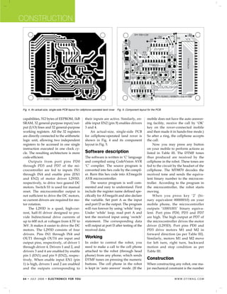
SlideShare a Scribd company logo
1 of 4
Download to read offline
Construction


 Cellphone-Operated
 Land Rover
  P Raghavendra PRASAD and
    .                                                     no interference with other controllers                     Parts List
 K. Susram Rahul                                          and up to twelve controls.
                                                                                                      Semiconductors:
                                                              Although the appearance and


 C
                                                                                                      IC1	            -	MT8870 DTMF decoder
         onventionally, wireless-con-                     capabilities of robots vary vastly,         IC2	            -	ATmega16 AVR
         trolled robots use RF circuits,                  all robots share the features of a me-      		 microcontroller
         which have the drawbacks of                      chanical, movable structure under           IC3	            -	L293D motor driver
                                                                                                      IC4	            -	74LS04 NOT gate
 limited working range, limited fre-                      some form of control. The control of
                                                                                                      D1	             -	1N4007 rectifier diode
 quency range and limited control. Use                    robot involves three distinct phases:
 of a mobile phone for robotic control                    preception, processing and action.          Resistors (all ¼-watt, ±5% carbon):
                                                                                                      R1, R2	          -	100-kilo-ohm
 can overcome these limitations. It                       Generally, the preceptors are sensors       R3	              -	330-kilo-ohm
 provides the advantages of robust                        mounted on the robot, processing is         R4-R8	           -	10-kilo-ohm
 control, working range as large as the                   done by the on-board microcontrol-
                                                                                                      Capacitors:
 coverage area of the service provider,                   ler or processor, and the task (action)     C1	             -	0.47µF ceramic disk
                                                                          is performed using          C2, C3, C5, C6 	-	22pF ceramic disk
                                                                          motors or with some         C4	             -	0.1µF ceramic disk
                                                                          other actuators.            Miscellaneous:
                                                                                                      XTAL1	         -	3.57MHz crystal
                                                                           Project                    XTAL2	         -	12MHz crystal
                                                                           overview                   S1	            -	Push-to-on switch
                                                                                                      M1, M2	        -	6V, 50-rpm geared
                                                                           In this project, the       		 DC motor
                                                                           robot is controlled        Batt.	         -	6V, 4.5Ah battery
                                                                           by a mobile phone
                                                                           that makes a call to       a tone corresponding to the button
                                                                           the mobile phone at-       pressed is heard at the other end of
                                                                           tached to the robot. In    the call. This tone is called ‘dual-tone
                                                                           the course of a call, if   multiple-frequency’ (DTMF) tone.
 Fig. 1: Block diagram of cellphone-operated land rover                    any button is pressed,     The robot perceives this DTMF tone


 Fig. 2: Circuit diagram of microcontroller-based cellphone-operated land rover


 6 2 • j u ly 2 0 0 8 • e l e c t ro n i c s f o r yo u                                                                      w w w. e f y m ag . co m
Construction
with the help of the phone stacked in                decoder decodes the DTMF
the robot.                                           tone into its equivalent bi-
    The received tone is processed by                nary digit and this binary
the ATmega16 microcontroller with the                number is sent to the micro-
help of DTMF decoder MT8870. The                     controller. The microcontrol-
                                                         ler is preprogrammed to
                      Table I                            take a decision for any
         Tones and Assignments                           given input and out-
           in a DTMF System                              puts its decision to motor
Frequencies 	 1209 Hz 	 1336 Hz 	 1477 Hz 	 1633 Hz drivers in order to drive
                                                         the motors for forward
697 Hz	          1	        2	          3	       A
                                                         or backward motion or
770 Hz	          4	        5	          6	       B
                                                         a turn.
852 Hz	          7	        8	          9	       C             T h e m o b i l e t h a t Fig. 3: Top view of the land rover
941 Hz 	         *	        0	         #	        D        makes a call to the mo-
                                                                    bile phone stacked in the          gebraic summation, in real time, of
                          Table II                                  robot acts as a remote. So         the amplitudes of two sine (cosine)
                 DTMF Data Output                                   this simple robotic project        waves of different frequencies, i.e.,
                                                                    does not require the con-          pressing ‘5’ will send a tone made
Low 	          High 	     Digit 	 OE 	 D3 	 D2 	 D1 	 D0
group (Hz)	 group (Hz)						                                        struction of receiver and          by adding 1336 Hz and 770 Hz to the
                                                                    transmitter units.                 other end of the line. The tones and
697	           1209	        1	      H	    L	      L	    L	     H
                                                                        DTMF signaling is              assignments in a DTMF system are
697	           1336	        2	      H	    L	      L	    H	     L
                                                                    used for telephone sign-           shown in Table I.
697	           1477	        3	      H	    L	      L	    H	     H    aling over the line in the
770	           1209	        4	      H	    L	      H	    L	     L    voice-frequency band to            Circuit description
770	           1336	        5	      H	    L	      H	    L	     H    the call switching centre.         Fig. 1 shows the block diagram of the
770	           1477	        6	      H	    L	      H	    H	     L    The version of DTMF                microcontroller-based mobile phone-
852	           1209	        7	      H	    L	      H	    H	     H    used for telephone tone            operated land rover. The important
852	           1336	        8	      H	    H	      L	    L	     L    dialing is known as                components of this rover are a DTMF
852	           1477	        9	      H	    H	      L	    L	     H    ‘Touch-Tone.’                      decoder, microcontroller and motor
941	           1336	        0	      H	    H	      L	    H	     L        DTMF assigns a spe-            driver.
941	           1209	        *	      H	    H	      L	    H	     H    cific frequency (con-                   An MT8870 series DTMF decoder
941	           1477	       #	       H	    H	      H	    L	     L    sisting of two separate            is used here. All types of the MT8870
                                                                    tones) to each key so              series use digital counting techniques
697	           1633	       A	       H	    H	      H	    L	     H
                                                                    that it can easily be              to detect and decode all the 16 DTMF
770	           1633	       B	       H	    H	      H	    H	     L
                                                                    identified by the elec-            tone pairs into a 4-bit code output. The
852	           1633	       C	       H	    H	      H	    H	     H
                                                                    tronic circuit. The signal         built-in dial tone rejection circuit elimi-
941	           1633	       D	       H	    L	      L	    L	     L
                                                                    generated by the DTMF              nates the need for pre-filtering. When
—	              —	        ANY	      L	    Z	      Z	    Z	     Z    encoder is a direct al-            the input signal given at pin 2 (IN-) in
                                                                                                       single-ended input configuration is
                                           Table III                                                   recognised to be effective, the correct
                                                                                                       4-bit decode signal of the DTMF tone is
      Actions Performed Corresponding to the Keys Pressed
                                                                                                       transferred to Q1 (pin 11) through Q4
Number 	 Output of HT9170	 Input to the 	             Output from 	Action                              (pin 14) outputs.
pressed 	 DTMF decoder	          microcontroller	     microcontroller	   performed
                                                                                                            Table II shows the DTMF data
by user
                                                                                                       output table of MT8870. Q1 through
2	         0×02	                 0×FD	                0×89	              Forward motion	               Q4 outputs of the DTMF decoder (IC1)
	          00000010	             11111101	            10001001	
                                                                                                       are connected to port pins PA0 through
4	         0×04	                 0XFB	                0×85	              Left turn	
                                                                                                       PA3 of ATmega16 microcontroller
	          00000100	             11111011	            10000101	          Right motor forwarded	
	          	                     	                    	                  Left motor backwarded         (IC2) after inversion by N1 through N4,
6	         0×06	                 0XF9	                0×8A	              Right turn	                   respectively.
	          00000110	             11111001	            10001010	          Right motor backwarded	            The ATmega16 is a low-power,
	          	                     	                    	                  Left motor forwarded          8-bit, CMOS microcontroller based on
8	         0×08	                 0XF7	                0×86	              Backward motion	              the AVR enhanced RISC architecture. It
	          00001000	             11110111	            10000110	                                        provides the following features: 16 kB
5	         0×05	                 0XFA	                0×00	              Stop	                         of in-system programmable Flash pro-
	          00000101	             11111010	            00000000	                                        gram memory with read-while-write


w w w. e f y m ag . co m                                                                           e l e c t ro n i c s f o r yo u • j u ly 2 0 0 8 • 6 3
Construction


 Fig. 4: An actual-size, single-side PCB layout for cellphone-operated land rover   Fig. 5: Component layout for the PCB


 capabilities, 512 bytes of EEPROM, 1kB                   their inputs are active. Similarly, en-           mobile does not have the auto answer-
 SRAM, 32 general-purpose input/out-                      able input EN2 (pin 9) enables drivers            ing facility, receive the call by ‘OK’
 put (I/O) lines and 32 general-purpose                   3 and 4.                                          key on the rover-connected mobile
 working registers. All the 32 registers                      An actual-size, single-side PCB               and then made it in hands-free mode.)
 are directly connected to the arithmetic                 for cellphone-operated land rover is              So after a ring, the cellphone accepts
 logic unit, allowing two independent                     shown in Fig. 4 and its component                 the call.
 registers to be accessed in one single                   layout in Fig. 5.                                     Now you may press any button
 instruction executed in one clock cy-                                                                      on your mobile to perform actions as
 cle. The resulting architecture is more                  Software description                              listed in Table III. The DTMF tones
 code-efficient.                                          The software is written in ‘C’ language           thus produced are received by the
     Outputs from port pins PD0                           and compiled using CodeVision AVR                 cellphone in the robot. These tones are
 through PD3 and PD7 of the mi-                           ‘C’ compiler. The source program is               fed to the circuit by the headset of the
 crocontroller are fed to inputs IN1                      converted into hex code by the compil-            cellphone. The MT8870 decodes the
 through IN4 and enable pins (EN1                         er. Burn this hex code into ATmega16              received tone and sends the equiva-
 and EN2) of motor driver L293D,                          AVR microcontroller.                              lent binary number to the microcon-
 respectively, to drive two geared DC                          The source program is well com-              troller. According to the program in
 motors. Switch S1 is used for manual                     mented and easy to understand. First              the microcontroller, the robot starts
 reset. The microcontroller output is                     include the register name defined spe-            moving.
 not sufficient to drive the DC motors,                   cifically for ATmega16 and also declare               When you press key ‘2’ (bi-
 so current drivers are required for mo-                  the variable. Set port A as the input             nary equivalent 00000010) on your
 tor rotation.                                            and port D as the output. The program             mobile phone, the microcontroller
     The L293D is a quad, high-cur-                       will run forever by using ‘while’ loop.           outputs ‘10001001’ binary equiva-
 rent, half-H driver designed to pro-                     Under ‘while’ loop, read port A and               lent. Port pins PD0, PD3 and PD7
 vide bidirectional drive currents of                     test the received input using ‘switch’            are high. The high output at PD7 of
 up to 600 mA at voltages from 4.5V to                    statement. The corresponding data                 the microcontroller drives the motor
 36V. It makes it easier to drive the DC                  will output at port D after testing of the        driver (L293D). Port pins PD0 and
 motors. The L293D consists of four                       received data.                                    PD3 drive motors M1 and M2 in
 drivers. Pins IN1 through IN4 and                                                                          forward direction (as per Table III).
 OUT1 through OUT4 are input and                          Working                                           Similarly, motors M1 and M2 move
 output pins, respectively, of driver 1                   In order to control the robot, you                for left turn, right turn, backward
 through driver 4. Drivers 1 and 2, and                   need to make a call to the cell phone             motion and stop condition as per
 drivers 3 and 4 are enabled by enable                    attached to the robot (through head               Table III.
 pin 1 (EN1) and pin 9 (EN2), respec-                     phone) from any phone, which sends
 tively. When enable input EN1 (pin                       DTMF tunes on pressing the numeric                Construction
 1) is high, drivers 1 and 2 are enabled                  buttons. The cell phone in the robot              When constructing any robot, one ma-
 and the outputs corresponding to                         is kept in ‘auto answer’ mode. (If the            jor mechanical constraint is the number


 6 4 • j u ly 2 0 0 8 • e l e c t ro n i c s f o r yo u                                                                        w w w. e f y m ag . co m
Construction
 of motors being used. You can have ei-                   Motors are fixed to the bottom of this     Further applications
 ther a two-wheel drive or a four-wheel                   sheet and the circuit is affixed firmly    This land rover can be further im-
 drive. Though four-wheel drive is more                   on top of the sheet. A cellphone is also   proved to serve specific purposes. It
 complex than two-wheel drive, it pro-                    mounted on the sheet as shown in the       requires four controls to roam around.
 vides more torque and good control.                      picture.                                   The remaining eight controls can be
 Two-wheel drive, on the other hand, is                       In the four-wheel drive system,        configured to serve other purposes,
 very easy to construct.                                  the two motors on a side are control-      with some modifications in the source
     Top view of a four-wheel-driven                      led in parallel. So a single L293D         program of the microcontroller.
 land rover is shown in Fig. 3. The                       driver IC can drive the rover. For this        Note. The source code of this arti-
 chassis used in this model is a                          robot, beads affixed with glue act as      cle has been included in this month’s
 10×18cm2 sheet made up of parax.                         support wheels.                            EFY CD.

                                                                          Robot.C
 Source program:                                          	 case 0x02: //if I/P is 0x02              	 }
 Robit.c                                                  	 {                                        	 case 0x06:	
 #include <mega16.h>                                      	 PORTD=0x89;//O/P 0x89 ie Forward         	 {
 void main(void)                                          	 break;                                   	 PORTD=0x8A; // Right turn
  {                                                       	 }                                        	 break;
 	 unsigned int k, h;                                     	 case 0x08: //if I/P is 	 0x08            	 }
 	 DDRA=0x00;                                             	 {                                        	 case 0x05:	
 	 DDRD=0XFF;	                                            	 PORTD=0x86; //O/P 0x86 ie Backward       	 {
  while (1)                                               	 break;                                   	 PORTD=0x00; // Stop
  {                                                       	 }                                        	 break;
 	 k =~PINA;                                              	 case 0x04:	                              	 }
 	 h=k & 0x0F;                                            	 {                                        	 }
  switch (h)                                              	 PORTD=0x85; // Left turn                 	 }
 	 {                                                      	 break;                                   	 }    	                                


 6 6 • j u ly 2 0 0 8 • e l e c t ro n i c s f o r yo u                                                                w w w. e f y m ag . co m

More Related Content

What's hot

Ensemble rxtx, receptor SDR.
Ensemble rxtx, receptor SDR.Ensemble rxtx, receptor SDR.
Ensemble rxtx, receptor SDR.Ricardo Vergara
 
A low power rf id transponder
A low power rf id transponderA low power rf id transponder
A low power rf id transponderBien Morfe
 
Elm327 Use Manual - How to use elm327 obd 2 scanner
Elm327 Use Manual - How to use elm327 obd 2 scannerElm327 Use Manual - How to use elm327 obd 2 scanner
Elm327 Use Manual - How to use elm327 obd 2 scannerjosy jiang
 
Cables de acceso y de gestion ericsson y nec pasolink
Cables de acceso y de gestion ericsson y nec pasolinkCables de acceso y de gestion ericsson y nec pasolink
Cables de acceso y de gestion ericsson y nec pasolinkdidiersep
 
Acx502 bmu
Acx502 bmuAcx502 bmu
Acx502 bmuUjwal Ks
 
PC Board Relays - 25 Series
PC Board Relays - 25 SeriesPC Board Relays - 25 Series
PC Board Relays - 25 SeriesWerner Electric
 
Optimization of Digitally Controlled Oscillator with Low Power
Optimization of Digitally Controlled Oscillator with Low PowerOptimization of Digitally Controlled Oscillator with Low Power
Optimization of Digitally Controlled Oscillator with Low Poweriosrjce
 
Micro p test
Micro p testMicro p test
Micro p testnurhelmi
 
Rs 232 Eia 232 Serial Interface Pinout
Rs 232 Eia 232 Serial Interface PinoutRs 232 Eia 232 Serial Interface Pinout
Rs 232 Eia 232 Serial Interface PinoutSais Abdelkrim
 
The International Journal of Engineering and Science (The IJES)
The International Journal of Engineering and Science (The IJES)The International Journal of Engineering and Science (The IJES)
The International Journal of Engineering and Science (The IJES)theijes
 
Embedded System Microcontroller Interactive Course using BASCOM-AVR - Lecture10
Embedded System Microcontroller Interactive Course using BASCOM-AVR - Lecture10Embedded System Microcontroller Interactive Course using BASCOM-AVR - Lecture10
Embedded System Microcontroller Interactive Course using BASCOM-AVR - Lecture10AL-AWAIL for Electronic Engineering
 

What's hot (19)

Ensemble rxtx, receptor SDR.
Ensemble rxtx, receptor SDR.Ensemble rxtx, receptor SDR.
Ensemble rxtx, receptor SDR.
 
Cd4047
Cd4047Cd4047
Cd4047
 
A low power rf id transponder
A low power rf id transponderA low power rf id transponder
A low power rf id transponder
 
Elm327 Use Manual - How to use elm327 obd 2 scanner
Elm327 Use Manual - How to use elm327 obd 2 scannerElm327 Use Manual - How to use elm327 obd 2 scanner
Elm327 Use Manual - How to use elm327 obd 2 scanner
 
Cables de acceso y de gestion ericsson y nec pasolink
Cables de acceso y de gestion ericsson y nec pasolinkCables de acceso y de gestion ericsson y nec pasolink
Cables de acceso y de gestion ericsson y nec pasolink
 
9530 datasheet
9530 datasheet9530 datasheet
9530 datasheet
 
Acx502 bmu
Acx502 bmuAcx502 bmu
Acx502 bmu
 
Sv200ma mi1e
Sv200ma mi1eSv200ma mi1e
Sv200ma mi1e
 
Vantage Multiswitch
Vantage MultiswitchVantage Multiswitch
Vantage Multiswitch
 
Z xra zxrp_repeaters
Z xra zxrp_repeatersZ xra zxrp_repeaters
Z xra zxrp_repeaters
 
Synthesizers
SynthesizersSynthesizers
Synthesizers
 
PC Board Relays - 25 Series
PC Board Relays - 25 SeriesPC Board Relays - 25 Series
PC Board Relays - 25 Series
 
Optimization of Digitally Controlled Oscillator with Low Power
Optimization of Digitally Controlled Oscillator with Low PowerOptimization of Digitally Controlled Oscillator with Low Power
Optimization of Digitally Controlled Oscillator with Low Power
 
Micro p test
Micro p testMicro p test
Micro p test
 
Rs 232 Eia 232 Serial Interface Pinout
Rs 232 Eia 232 Serial Interface PinoutRs 232 Eia 232 Serial Interface Pinout
Rs 232 Eia 232 Serial Interface Pinout
 
Adf7901
Adf7901Adf7901
Adf7901
 
The International Journal of Engineering and Science (The IJES)
The International Journal of Engineering and Science (The IJES)The International Journal of Engineering and Science (The IJES)
The International Journal of Engineering and Science (The IJES)
 
Embedded System Microcontroller Interactive Course using BASCOM-AVR - Lecture10
Embedded System Microcontroller Interactive Course using BASCOM-AVR - Lecture10Embedded System Microcontroller Interactive Course using BASCOM-AVR - Lecture10
Embedded System Microcontroller Interactive Course using BASCOM-AVR - Lecture10
 
Emp
EmpEmp
Emp
 

Viewers also liked

Organizational design qm
Organizational design qmOrganizational design qm
Organizational design qmAshu0711
 
450 q &a for tcs
450 q &a for tcs450 q &a for tcs
450 q &a for tcsAshu0711
 
Project landrover
Project landroverProject landrover
Project landroverAshu0711
 
All placementpapers
All placementpapersAll placementpapers
All placementpapersAshu0711
 
Mini p gsm based display
Mini p gsm based displayMini p gsm based display
Mini p gsm based displayAshu0711
 
Quality management concepts
Quality management conceptsQuality management concepts
Quality management conceptsAshu0711
 
Gsm anti theft system
Gsm anti theft systemGsm anti theft system
Gsm anti theft systemAshu0711
 
gsm based security system
gsm based security systemgsm based security system
gsm based security systemnayandey
 

Viewers also liked (10)

Organizational design qm
Organizational design qmOrganizational design qm
Organizational design qm
 
450 q &a for tcs
450 q &a for tcs450 q &a for tcs
450 q &a for tcs
 
Project landrover
Project landroverProject landrover
Project landrover
 
All placementpapers
All placementpapersAll placementpapers
All placementpapers
 
Fear of public
Fear of publicFear of public
Fear of public
 
Mini p gsm based display
Mini p gsm based displayMini p gsm based display
Mini p gsm based display
 
Quality management concepts
Quality management conceptsQuality management concepts
Quality management concepts
 
Gsm anti theft system
Gsm anti theft systemGsm anti theft system
Gsm anti theft system
 
gsm based security system
gsm based security systemgsm based security system
gsm based security system
 
SMART Vehicle Secure PPT
SMART Vehicle Secure PPTSMART Vehicle Secure PPT
SMART Vehicle Secure PPT
 

Similar to Cellphone land rover

Mobile Operated Landrover Using Dtmf Decoder
Mobile Operated Landrover Using Dtmf DecoderMobile Operated Landrover Using Dtmf Decoder
Mobile Operated Landrover Using Dtmf DecoderIJMER
 
Bw32898902
Bw32898902Bw32898902
Bw32898902IJMER
 
Cell Phone Operated Vehicle
Cell Phone Operated VehicleCell Phone Operated Vehicle
Cell Phone Operated Vehicleprasanna naik
 
Cell operated land rover robot
Cell operated land rover robotCell operated land rover robot
Cell operated land rover robotChetan Kataria
 
Cellphone signal detector and jammer ppt
Cellphone signal detector and jammer pptCellphone signal detector and jammer ppt
Cellphone signal detector and jammer pptAmar Raj
 
Fire Fighter Robot with Night Vision Camera (1).pptx
Fire Fighter Robot with Night Vision Camera (1).pptxFire Fighter Robot with Night Vision Camera (1).pptx
Fire Fighter Robot with Night Vision Camera (1).pptxSyedMohiuddin62
 
DTMF BASED MOBILE CONTROLL ROBOT SYSTEM
DTMF BASED MOBILE CONTROLL ROBOT SYSTEMDTMF BASED MOBILE CONTROLL ROBOT SYSTEM
DTMF BASED MOBILE CONTROLL ROBOT SYSTEMiindranilsarkar
 
Ppt land rover
Ppt land roverPpt land rover
Ppt land roverAshu0711
 
Navigation of Robot Vehicle using RF with Landmine Detection
Navigation of Robot Vehicle using RF with Landmine DetectionNavigation of Robot Vehicle using RF with Landmine Detection
Navigation of Robot Vehicle using RF with Landmine DetectionVeena Rani
 
ACCELEROMETER BASED GESTURE ROBO CAR
ACCELEROMETER BASED GESTURE ROBO CARACCELEROMETER BASED GESTURE ROBO CAR
ACCELEROMETER BASED GESTURE ROBO CARHarshit Jain
 
Cell Phone Operated Land Rover
Cell Phone Operated Land RoverCell Phone Operated Land Rover
Cell Phone Operated Land RoverSanjay Talukdar
 
Cell phone operated robot synopsis
Cell phone operated robot synopsisCell phone operated robot synopsis
Cell phone operated robot synopsisgopal002
 
DTMF CONTROLLED ROBOT
DTMF CONTROLLED ROBOTDTMF CONTROLLED ROBOT
DTMF CONTROLLED ROBOTnarendra019
 
DTMF Based.ppt
DTMF Based.pptDTMF Based.ppt
DTMF Based.pptamol420898
 

Similar to Cellphone land rover (20)

Mobile Operated Landrover Using Dtmf Decoder
Mobile Operated Landrover Using Dtmf DecoderMobile Operated Landrover Using Dtmf Decoder
Mobile Operated Landrover Using Dtmf Decoder
 
Bw32898902
Bw32898902Bw32898902
Bw32898902
 
Cell Phone Operated Vehicle
Cell Phone Operated VehicleCell Phone Operated Vehicle
Cell Phone Operated Vehicle
 
Cell operated land rover robot
Cell operated land rover robotCell operated land rover robot
Cell operated land rover robot
 
Cellphone signal detector and jammer ppt
Cellphone signal detector and jammer pptCellphone signal detector and jammer ppt
Cellphone signal detector and jammer ppt
 
Pro final rep
Pro final repPro final rep
Pro final rep
 
Fire Fighter Robot with Night Vision Camera (1).pptx
Fire Fighter Robot with Night Vision Camera (1).pptxFire Fighter Robot with Night Vision Camera (1).pptx
Fire Fighter Robot with Night Vision Camera (1).pptx
 
DTMF BASED MOBILE CONTROLL ROBOT SYSTEM
DTMF BASED MOBILE CONTROLL ROBOT SYSTEMDTMF BASED MOBILE CONTROLL ROBOT SYSTEM
DTMF BASED MOBILE CONTROLL ROBOT SYSTEM
 
Ppt land rover
Ppt land roverPpt land rover
Ppt land rover
 
Spybot cum Surveillance Robo
Spybot cum Surveillance RoboSpybot cum Surveillance Robo
Spybot cum Surveillance Robo
 
Navigation of Robot Vehicle using RF with Landmine Detection
Navigation of Robot Vehicle using RF with Landmine DetectionNavigation of Robot Vehicle using RF with Landmine Detection
Navigation of Robot Vehicle using RF with Landmine Detection
 
ACCELEROMETER BASED GESTURE ROBO CAR
ACCELEROMETER BASED GESTURE ROBO CARACCELEROMETER BASED GESTURE ROBO CAR
ACCELEROMETER BASED GESTURE ROBO CAR
 
Metal Detector Robotic Vehicle
Metal Detector Robotic VehicleMetal Detector Robotic Vehicle
Metal Detector Robotic Vehicle
 
Cell Phone Operated Land Rover
Cell Phone Operated Land RoverCell Phone Operated Land Rover
Cell Phone Operated Land Rover
 
Cell phone operated robot synopsis
Cell phone operated robot synopsisCell phone operated robot synopsis
Cell phone operated robot synopsis
 
k10681
k10681k10681
k10681
 
final ppt2.pptx
final ppt2.pptxfinal ppt2.pptx
final ppt2.pptx
 
SURVEILLANCE ROBOT
SURVEILLANCE ROBOTSURVEILLANCE ROBOT
SURVEILLANCE ROBOT
 
DTMF CONTROLLED ROBOT
DTMF CONTROLLED ROBOTDTMF CONTROLLED ROBOT
DTMF CONTROLLED ROBOT
 
DTMF Based.ppt
DTMF Based.pptDTMF Based.ppt
DTMF Based.ppt
 

More from Ashu0711

Project ppt
Project pptProject ppt
Project pptAshu0711
 
My cad lab file
My cad lab fileMy cad lab file
My cad lab fileAshu0711
 
My cad file
My cad fileMy cad file
My cad fileAshu0711
 
Monolithic&amp;hybrid ic
Monolithic&amp;hybrid icMonolithic&amp;hybrid ic
Monolithic&amp;hybrid icAshu0711
 
Mini project-report
Mini project-reportMini project-report
Mini project-reportAshu0711
 
Metallization
MetallizationMetallization
MetallizationAshu0711
 
Anti theftsystemforvechicles1 final
Anti theftsystemforvechicles1 finalAnti theftsystemforvechicles1 final
Anti theftsystemforvechicles1 finalAshu0711
 
4.inverter final
4.inverter final4.inverter final
4.inverter finalAshu0711
 
3. solar water heater
3. solar water heater3. solar water heater
3. solar water heaterAshu0711
 
2.avr final
2.avr final2.avr final
2.avr finalAshu0711
 
Industrial training report format
Industrial training report formatIndustrial training report format
Industrial training report formatAshu0711
 
Mini p gsm based display
Mini p gsm based displayMini p gsm based display
Mini p gsm based displayAshu0711
 
Manufacturing quality qm
Manufacturing quality qmManufacturing quality qm
Manufacturing quality qmAshu0711
 
Gsm anti theft
Gsm anti theftGsm anti theft
Gsm anti theftAshu0711
 
Control on purchased product qm
Control on purchased product qmControl on purchased product qm
Control on purchased product qmAshu0711
 
Control chart qm
Control chart qmControl chart qm
Control chart qmAshu0711
 
16 x 16 banyan switch
16 x 16 banyan switch16 x 16 banyan switch
16 x 16 banyan switchAshu0711
 

More from Ashu0711 (20)

Project ppt
Project pptProject ppt
Project ppt
 
Pi q
Pi qPi q
Pi q
 
My cad lab file
My cad lab fileMy cad lab file
My cad lab file
 
My cad file
My cad fileMy cad file
My cad file
 
Monolithic&amp;hybrid ic
Monolithic&amp;hybrid icMonolithic&amp;hybrid ic
Monolithic&amp;hybrid ic
 
Mini project-report
Mini project-reportMini project-report
Mini project-report
 
Metallization
MetallizationMetallization
Metallization
 
Anti theftsystemforvechicles1 final
Anti theftsystemforvechicles1 finalAnti theftsystemforvechicles1 final
Anti theftsystemforvechicles1 final
 
4.inverter final
4.inverter final4.inverter final
4.inverter final
 
3. solar water heater
3. solar water heater3. solar water heater
3. solar water heater
 
2.avr final
2.avr final2.avr final
2.avr final
 
ups
upsups
ups
 
Industrial training report format
Industrial training report formatIndustrial training report format
Industrial training report format
 
Mini p gsm based display
Mini p gsm based displayMini p gsm based display
Mini p gsm based display
 
Manufacturing quality qm
Manufacturing quality qmManufacturing quality qm
Manufacturing quality qm
 
H bridge
H bridgeH bridge
H bridge
 
Gsm anti theft
Gsm anti theftGsm anti theft
Gsm anti theft
 
Control on purchased product qm
Control on purchased product qmControl on purchased product qm
Control on purchased product qm
 
Control chart qm
Control chart qmControl chart qm
Control chart qm
 
16 x 16 banyan switch
16 x 16 banyan switch16 x 16 banyan switch
16 x 16 banyan switch
 

Cellphone land rover

  • 1. Construction Cellphone-Operated Land Rover  P Raghavendra PRASAD and . no interference with other controllers Parts List K. Susram Rahul and up to twelve controls. Semiconductors: Although the appearance and C IC1 - MT8870 DTMF decoder onventionally, wireless-con- capabilities of robots vary vastly, IC2 - ATmega16 AVR trolled robots use RF circuits, all robots share the features of a me- microcontroller which have the drawbacks of chanical, movable structure under IC3 - L293D motor driver IC4 - 74LS04 NOT gate limited working range, limited fre- some form of control. The control of D1 - 1N4007 rectifier diode quency range and limited control. Use robot involves three distinct phases: of a mobile phone for robotic control preception, processing and action. Resistors (all ¼-watt, ±5% carbon): R1, R2 - 100-kilo-ohm can overcome these limitations. It Generally, the preceptors are sensors R3 - 330-kilo-ohm provides the advantages of robust mounted on the robot, processing is R4-R8 - 10-kilo-ohm control, working range as large as the done by the on-board microcontrol- Capacitors: coverage area of the service provider, ler or processor, and the task (action) C1 - 0.47µF ceramic disk is performed using C2, C3, C5, C6 - 22pF ceramic disk motors or with some C4 - 0.1µF ceramic disk other actuators. Miscellaneous: XTAL1 - 3.57MHz crystal Project XTAL2 - 12MHz crystal overview S1 - Push-to-on switch M1, M2 - 6V, 50-rpm geared In this project, the DC motor robot is controlled Batt. - 6V, 4.5Ah battery by a mobile phone that makes a call to a tone corresponding to the button the mobile phone at- pressed is heard at the other end of tached to the robot. In the call. This tone is called ‘dual-tone the course of a call, if multiple-frequency’ (DTMF) tone. Fig. 1: Block diagram of cellphone-operated land rover any button is pressed, The robot perceives this DTMF tone Fig. 2: Circuit diagram of microcontroller-based cellphone-operated land rover 6 2 • j u ly 2 0 0 8 • e l e c t ro n i c s f o r yo u w w w. e f y m ag . co m
  • 2. Construction with the help of the phone stacked in decoder decodes the DTMF the robot. tone into its equivalent bi- The received tone is processed by nary digit and this binary the ATmega16 microcontroller with the number is sent to the micro- help of DTMF decoder MT8870. The controller. The microcontrol- ler is preprogrammed to Table I take a decision for any Tones and Assignments given input and out- in a DTMF System puts its decision to motor Frequencies 1209 Hz 1336 Hz 1477 Hz 1633 Hz drivers in order to drive the motors for forward 697 Hz 1 2 3 A or backward motion or 770 Hz 4 5 6 B a turn. 852 Hz 7 8 9 C T h e m o b i l e t h a t Fig. 3: Top view of the land rover 941 Hz * 0 # D makes a call to the mo- bile phone stacked in the gebraic summation, in real time, of Table II robot acts as a remote. So the amplitudes of two sine (cosine) DTMF Data Output this simple robotic project waves of different frequencies, i.e., does not require the con- pressing ‘5’ will send a tone made Low High Digit OE D3 D2 D1 D0 group (Hz) group (Hz) struction of receiver and by adding 1336 Hz and 770 Hz to the transmitter units. other end of the line. The tones and 697 1209 1 H L L L H DTMF signaling is assignments in a DTMF system are 697 1336 2 H L L H L used for telephone sign- shown in Table I. 697 1477 3 H L L H H aling over the line in the 770 1209 4 H L H L L voice-frequency band to Circuit description 770 1336 5 H L H L H the call switching centre. Fig. 1 shows the block diagram of the 770 1477 6 H L H H L The version of DTMF microcontroller-based mobile phone- 852 1209 7 H L H H H used for telephone tone operated land rover. The important 852 1336 8 H H L L L dialing is known as components of this rover are a DTMF 852 1477 9 H H L L H ‘Touch-Tone.’ decoder, microcontroller and motor 941 1336 0 H H L H L DTMF assigns a spe- driver. 941 1209 * H H L H H cific frequency (con- An MT8870 series DTMF decoder 941 1477 # H H H L L sisting of two separate is used here. All types of the MT8870 tones) to each key so series use digital counting techniques 697 1633 A H H H L H that it can easily be to detect and decode all the 16 DTMF 770 1633 B H H H H L identified by the elec- tone pairs into a 4-bit code output. The 852 1633 C H H H H H tronic circuit. The signal built-in dial tone rejection circuit elimi- 941 1633 D H L L L L generated by the DTMF nates the need for pre-filtering. When — — ANY L Z Z Z Z encoder is a direct al- the input signal given at pin 2 (IN-) in single-ended input configuration is Table III recognised to be effective, the correct 4-bit decode signal of the DTMF tone is Actions Performed Corresponding to the Keys Pressed transferred to Q1 (pin 11) through Q4 Number Output of HT9170 Input to the Output from Action (pin 14) outputs. pressed DTMF decoder microcontroller microcontroller performed Table II shows the DTMF data by user output table of MT8870. Q1 through 2 0×02 0×FD 0×89 Forward motion Q4 outputs of the DTMF decoder (IC1) 00000010 11111101 10001001 are connected to port pins PA0 through 4 0×04 0XFB 0×85 Left turn PA3 of ATmega16 microcontroller 00000100 11111011 10000101 Right motor forwarded Left motor backwarded (IC2) after inversion by N1 through N4, 6 0×06 0XF9 0×8A Right turn respectively. 00000110 11111001 10001010 Right motor backwarded The ATmega16 is a low-power, Left motor forwarded 8-bit, CMOS microcontroller based on 8 0×08 0XF7 0×86 Backward motion the AVR enhanced RISC architecture. It 00001000 11110111 10000110 provides the following features: 16 kB 5 0×05 0XFA 0×00 Stop of in-system programmable Flash pro- 00000101 11111010 00000000 gram memory with read-while-write w w w. e f y m ag . co m e l e c t ro n i c s f o r yo u • j u ly 2 0 0 8 • 6 3
  • 3. Construction Fig. 4: An actual-size, single-side PCB layout for cellphone-operated land rover Fig. 5: Component layout for the PCB capabilities, 512 bytes of EEPROM, 1kB their inputs are active. Similarly, en- mobile does not have the auto answer- SRAM, 32 general-purpose input/out- able input EN2 (pin 9) enables drivers ing facility, receive the call by ‘OK’ put (I/O) lines and 32 general-purpose 3 and 4. key on the rover-connected mobile working registers. All the 32 registers An actual-size, single-side PCB and then made it in hands-free mode.) are directly connected to the arithmetic for cellphone-operated land rover is So after a ring, the cellphone accepts logic unit, allowing two independent shown in Fig. 4 and its component the call. registers to be accessed in one single layout in Fig. 5. Now you may press any button instruction executed in one clock cy- on your mobile to perform actions as cle. The resulting architecture is more Software description listed in Table III. The DTMF tones code-efficient. The software is written in ‘C’ language thus produced are received by the Outputs from port pins PD0 and compiled using CodeVision AVR cellphone in the robot. These tones are through PD3 and PD7 of the mi- ‘C’ compiler. The source program is fed to the circuit by the headset of the crocontroller are fed to inputs IN1 converted into hex code by the compil- cellphone. The MT8870 decodes the through IN4 and enable pins (EN1 er. Burn this hex code into ATmega16 received tone and sends the equiva- and EN2) of motor driver L293D, AVR microcontroller. lent binary number to the microcon- respectively, to drive two geared DC The source program is well com- troller. According to the program in motors. Switch S1 is used for manual mented and easy to understand. First the microcontroller, the robot starts reset. The microcontroller output is include the register name defined spe- moving. not sufficient to drive the DC motors, cifically for ATmega16 and also declare When you press key ‘2’ (bi- so current drivers are required for mo- the variable. Set port A as the input nary equivalent 00000010) on your tor rotation. and port D as the output. The program mobile phone, the microcontroller The L293D is a quad, high-cur- will run forever by using ‘while’ loop. outputs ‘10001001’ binary equiva- rent, half-H driver designed to pro- Under ‘while’ loop, read port A and lent. Port pins PD0, PD3 and PD7 vide bidirectional drive currents of test the received input using ‘switch’ are high. The high output at PD7 of up to 600 mA at voltages from 4.5V to statement. The corresponding data the microcontroller drives the motor 36V. It makes it easier to drive the DC will output at port D after testing of the driver (L293D). Port pins PD0 and motors. The L293D consists of four received data. PD3 drive motors M1 and M2 in drivers. Pins IN1 through IN4 and forward direction (as per Table III). OUT1 through OUT4 are input and Working Similarly, motors M1 and M2 move output pins, respectively, of driver 1 In order to control the robot, you for left turn, right turn, backward through driver 4. Drivers 1 and 2, and need to make a call to the cell phone motion and stop condition as per drivers 3 and 4 are enabled by enable attached to the robot (through head Table III. pin 1 (EN1) and pin 9 (EN2), respec- phone) from any phone, which sends tively. When enable input EN1 (pin DTMF tunes on pressing the numeric Construction 1) is high, drivers 1 and 2 are enabled buttons. The cell phone in the robot When constructing any robot, one ma- and the outputs corresponding to is kept in ‘auto answer’ mode. (If the jor mechanical constraint is the number 6 4 • j u ly 2 0 0 8 • e l e c t ro n i c s f o r yo u w w w. e f y m ag . co m
  • 4. Construction of motors being used. You can have ei- Motors are fixed to the bottom of this Further applications ther a two-wheel drive or a four-wheel sheet and the circuit is affixed firmly This land rover can be further im- drive. Though four-wheel drive is more on top of the sheet. A cellphone is also proved to serve specific purposes. It complex than two-wheel drive, it pro- mounted on the sheet as shown in the requires four controls to roam around. vides more torque and good control. picture. The remaining eight controls can be Two-wheel drive, on the other hand, is In the four-wheel drive system, configured to serve other purposes, very easy to construct. the two motors on a side are control- with some modifications in the source Top view of a four-wheel-driven led in parallel. So a single L293D program of the microcontroller. land rover is shown in Fig. 3. The driver IC can drive the rover. For this Note. The source code of this arti- chassis used in this model is a robot, beads affixed with glue act as cle has been included in this month’s 10×18cm2 sheet made up of parax. support wheels. EFY CD. Robot.C Source program: case 0x02: //if I/P is 0x02 } Robit.c { case 0x06: #include <mega16.h> PORTD=0x89;//O/P 0x89 ie Forward { void main(void) break; PORTD=0x8A; // Right turn { } break; unsigned int k, h; case 0x08: //if I/P is 0x08 } DDRA=0x00; { case 0x05: DDRD=0XFF; PORTD=0x86; //O/P 0x86 ie Backward { while (1) break; PORTD=0x00; // Stop { } break; k =~PINA; case 0x04: } h=k & 0x0F; { } switch (h) PORTD=0x85; // Left turn } { break; }  6 6 • j u ly 2 0 0 8 • e l e c t ro n i c s f o r yo u w w w. e f y m ag . co m