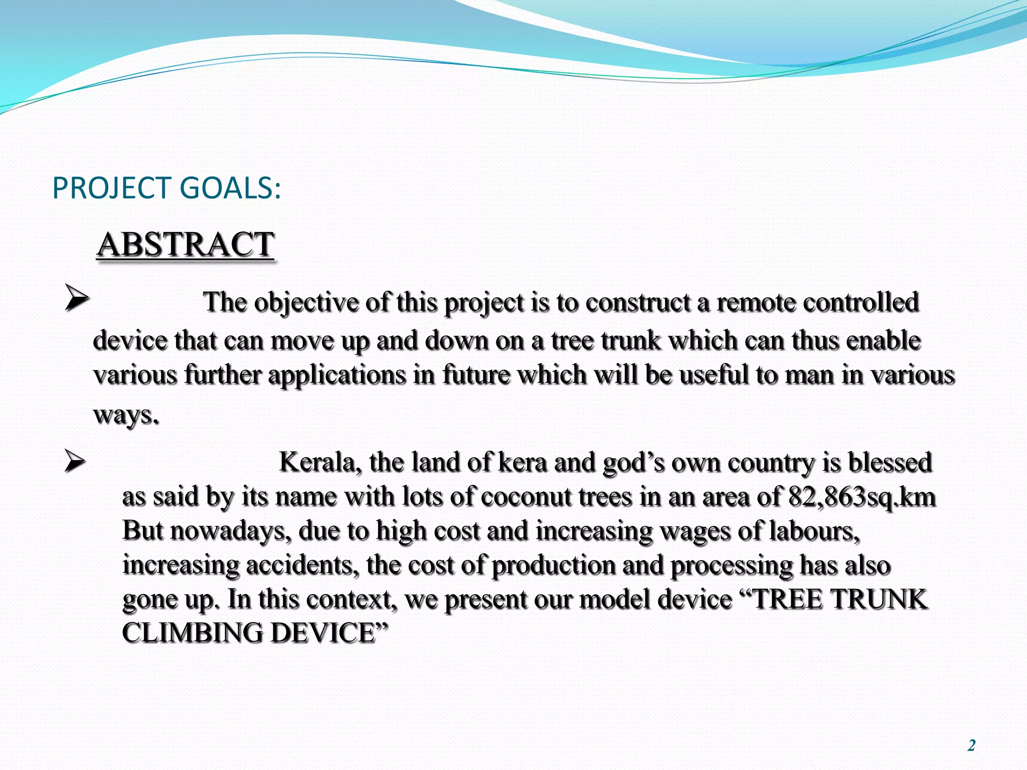
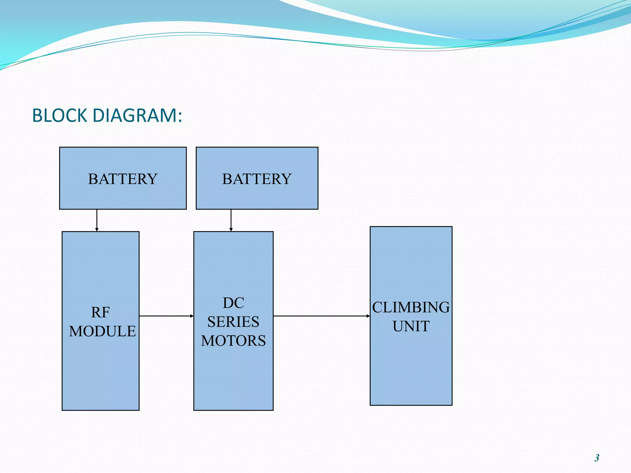
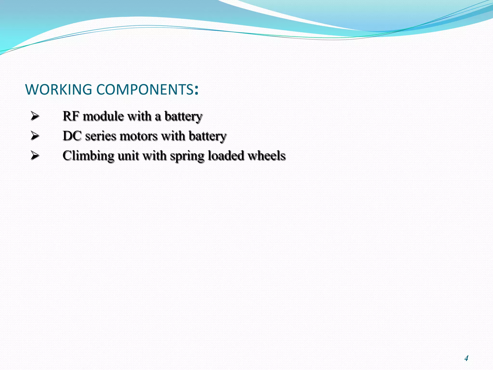
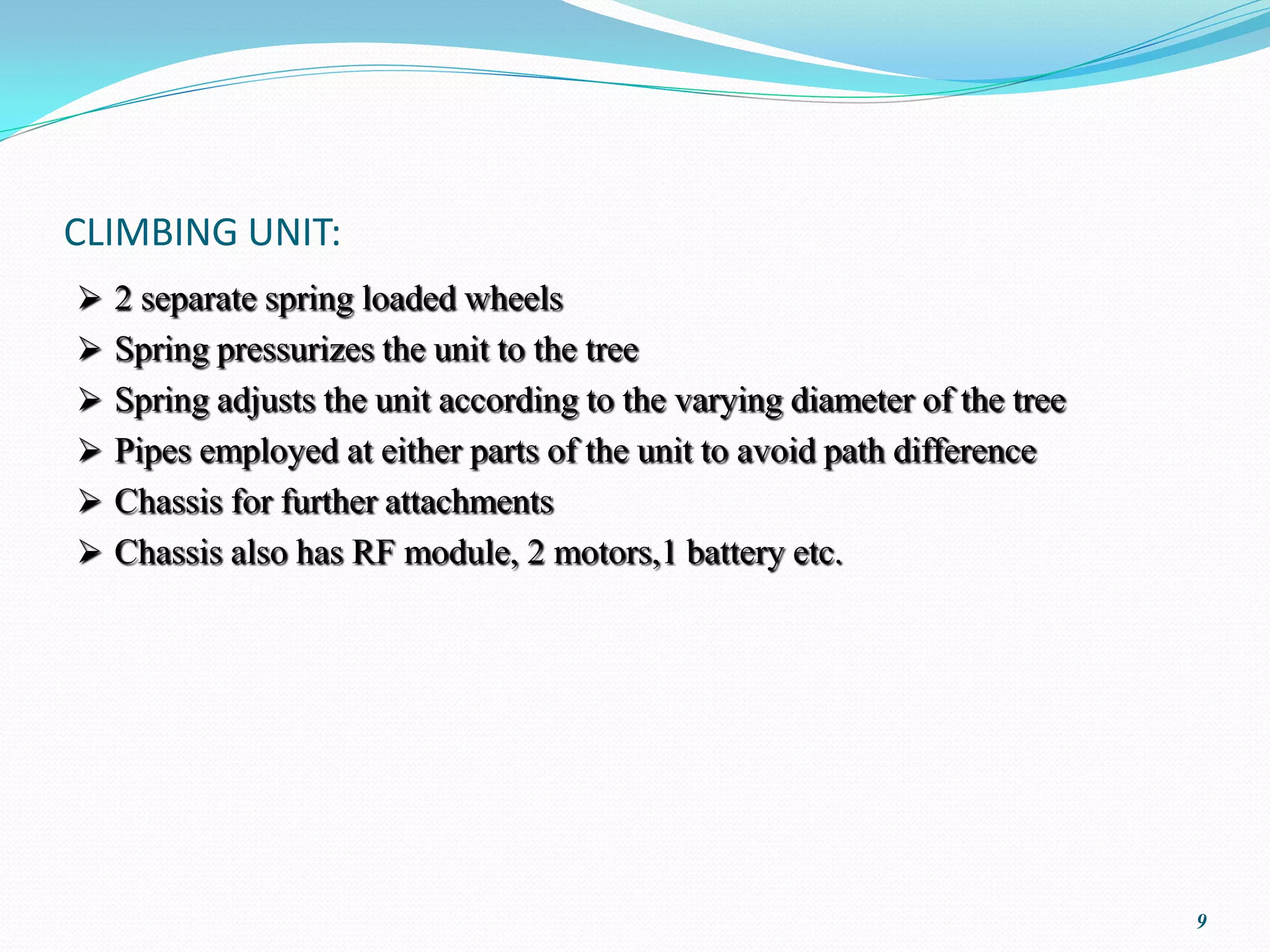
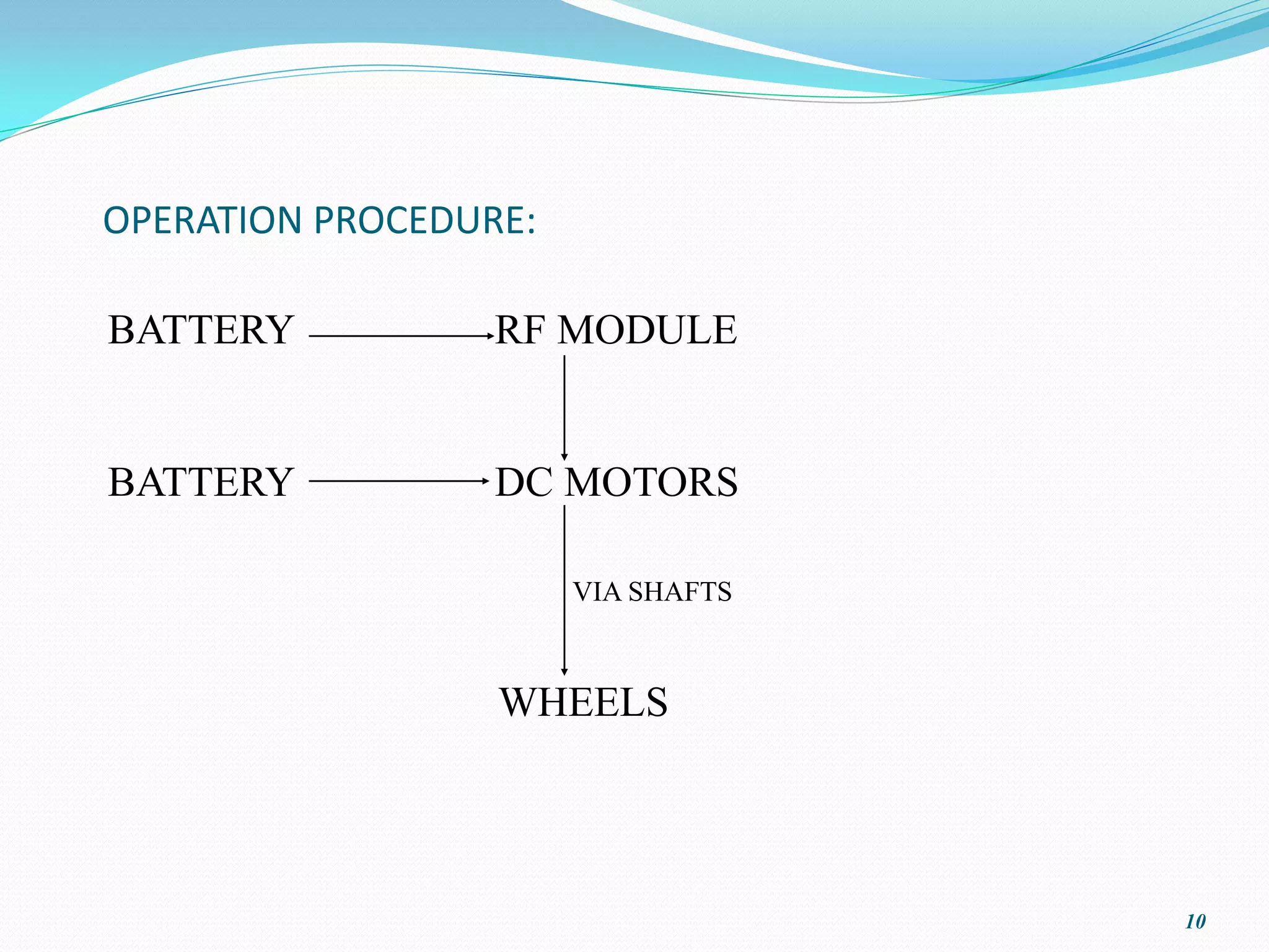
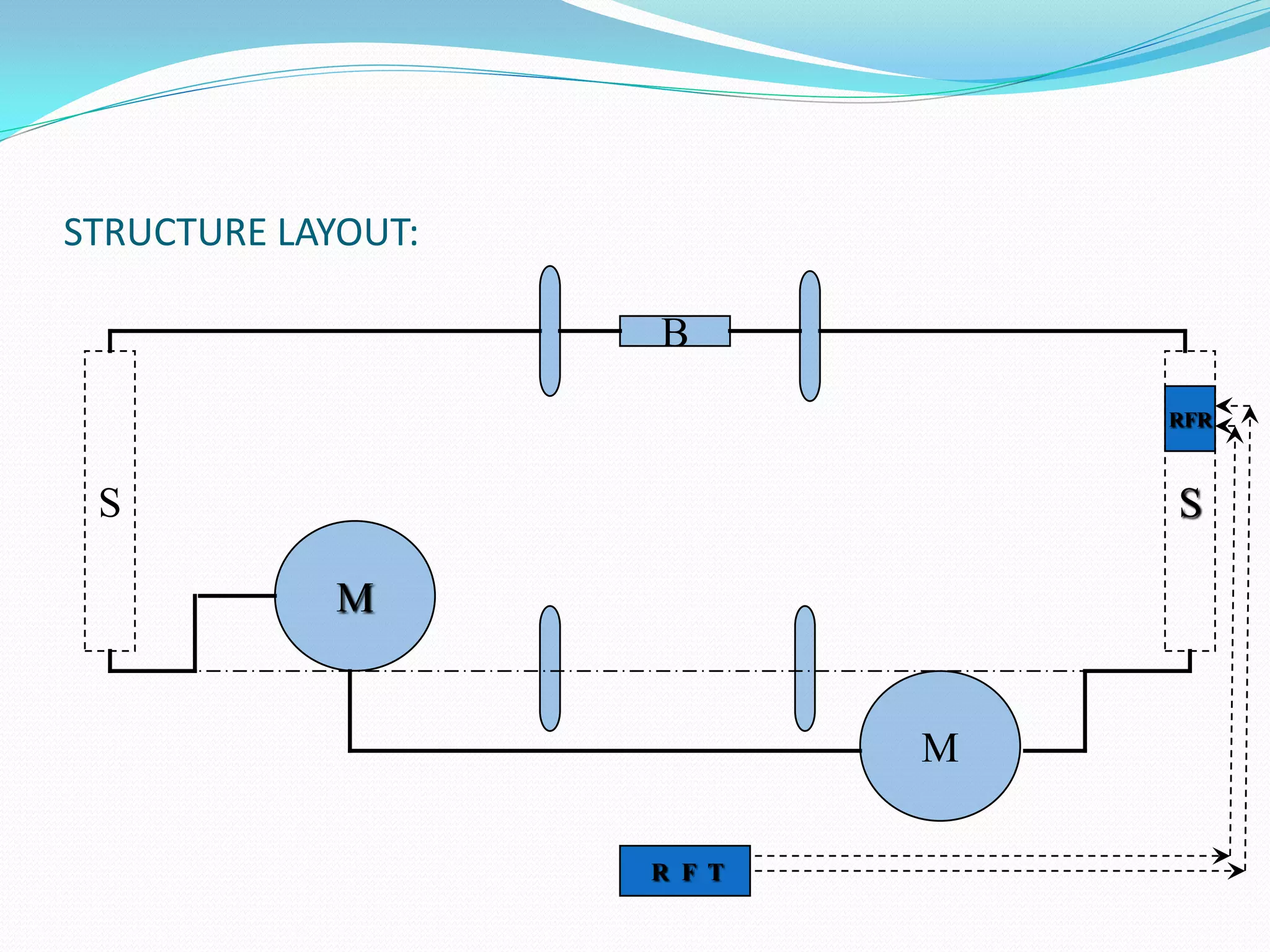
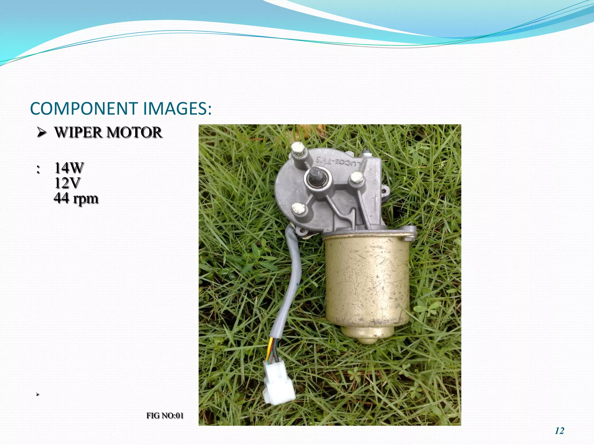
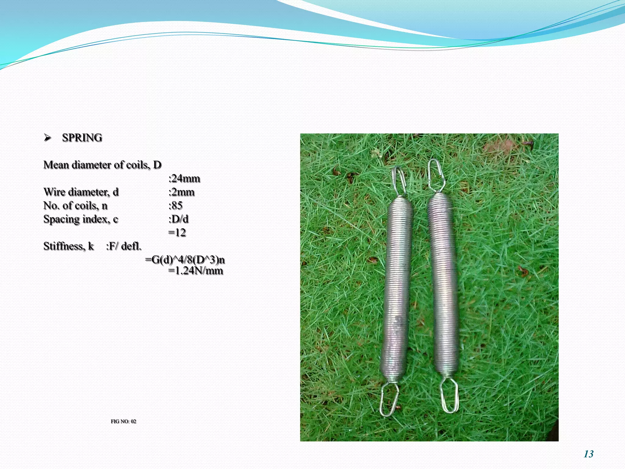
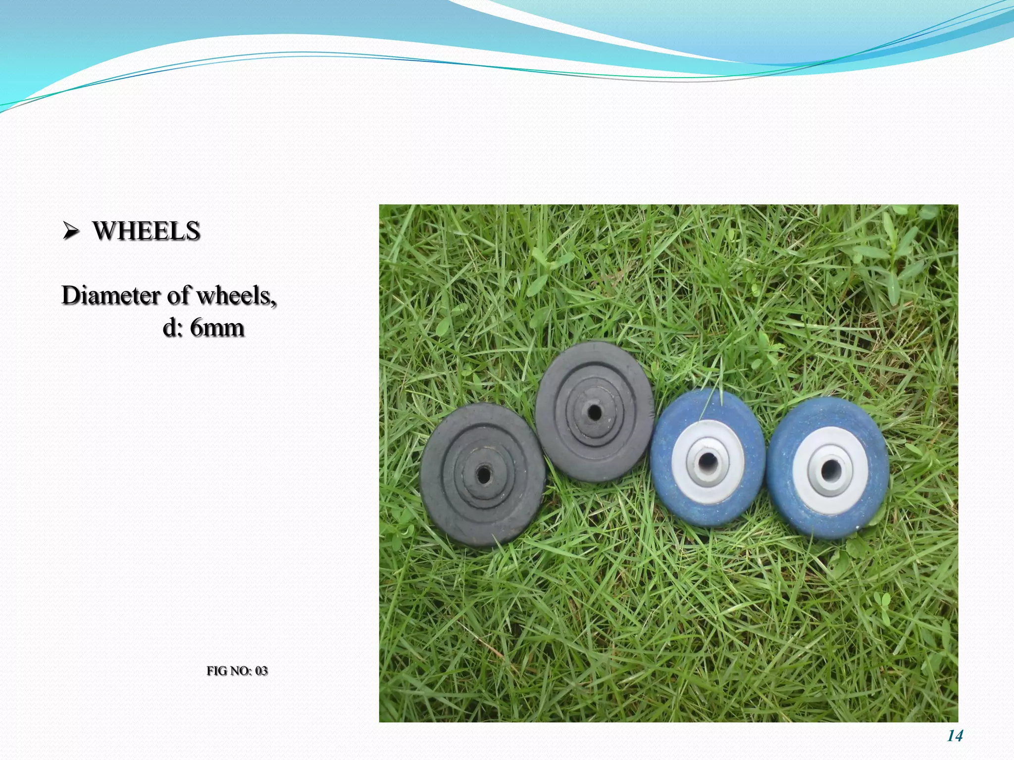
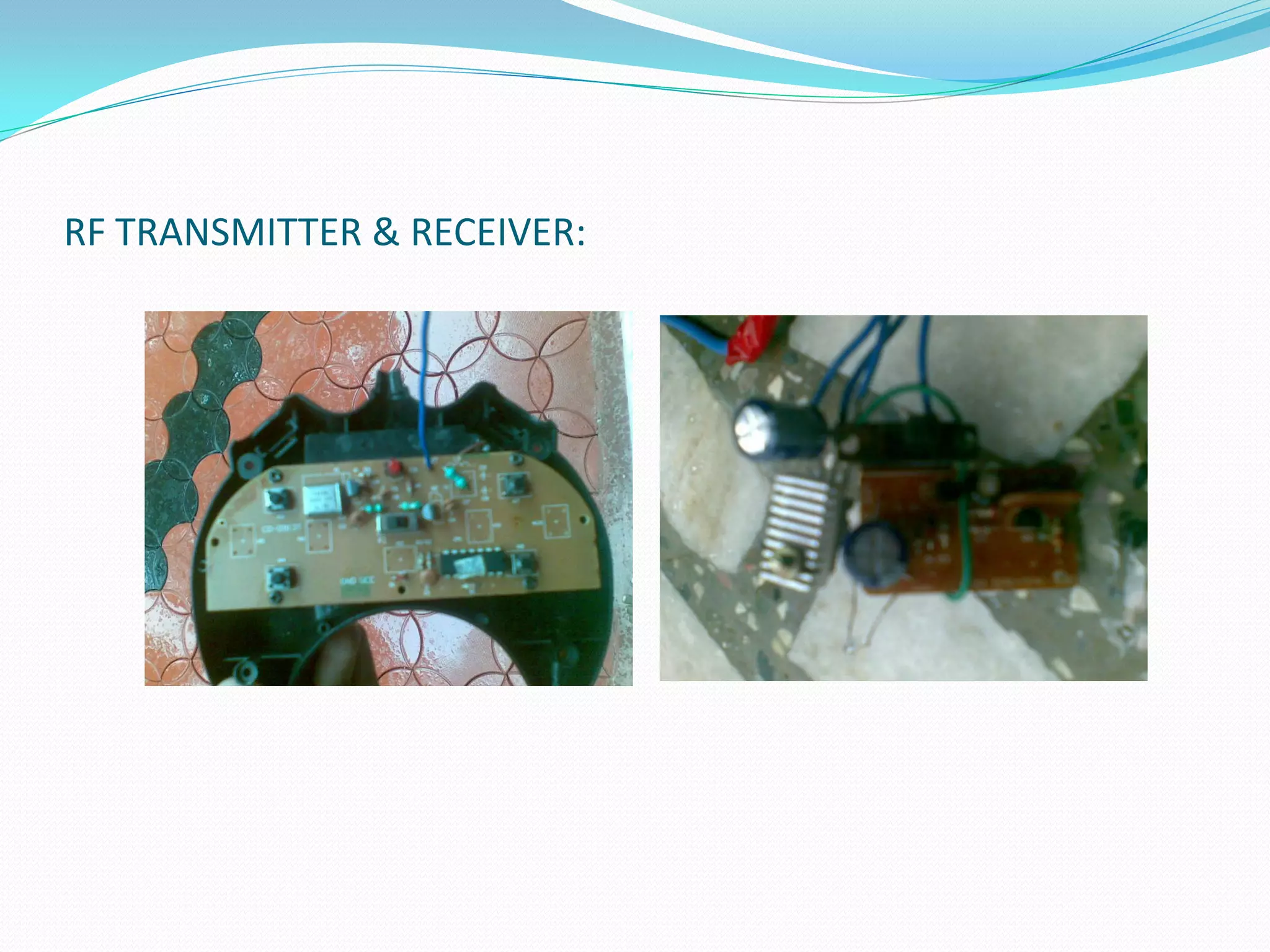
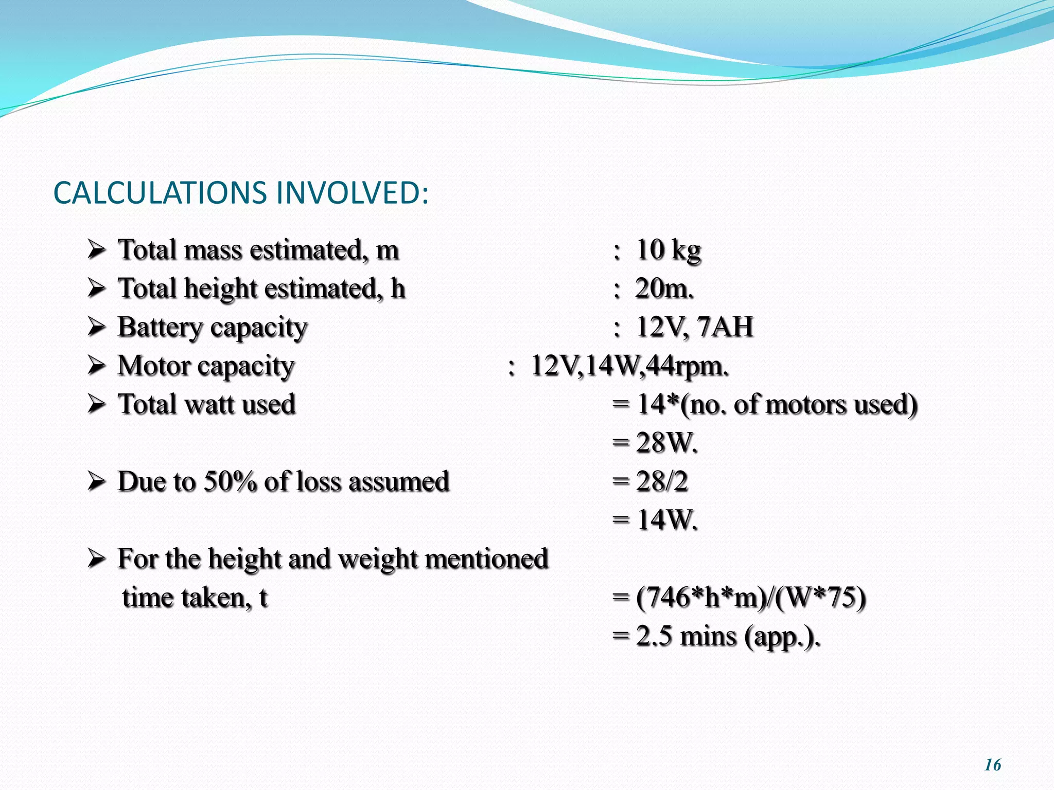
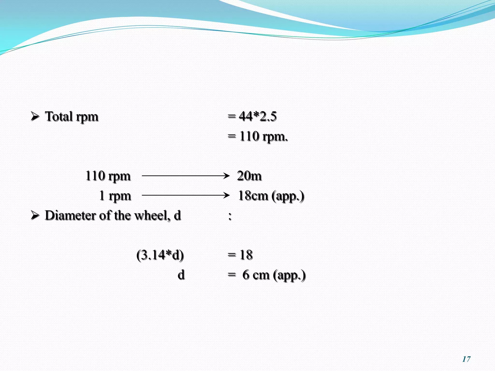
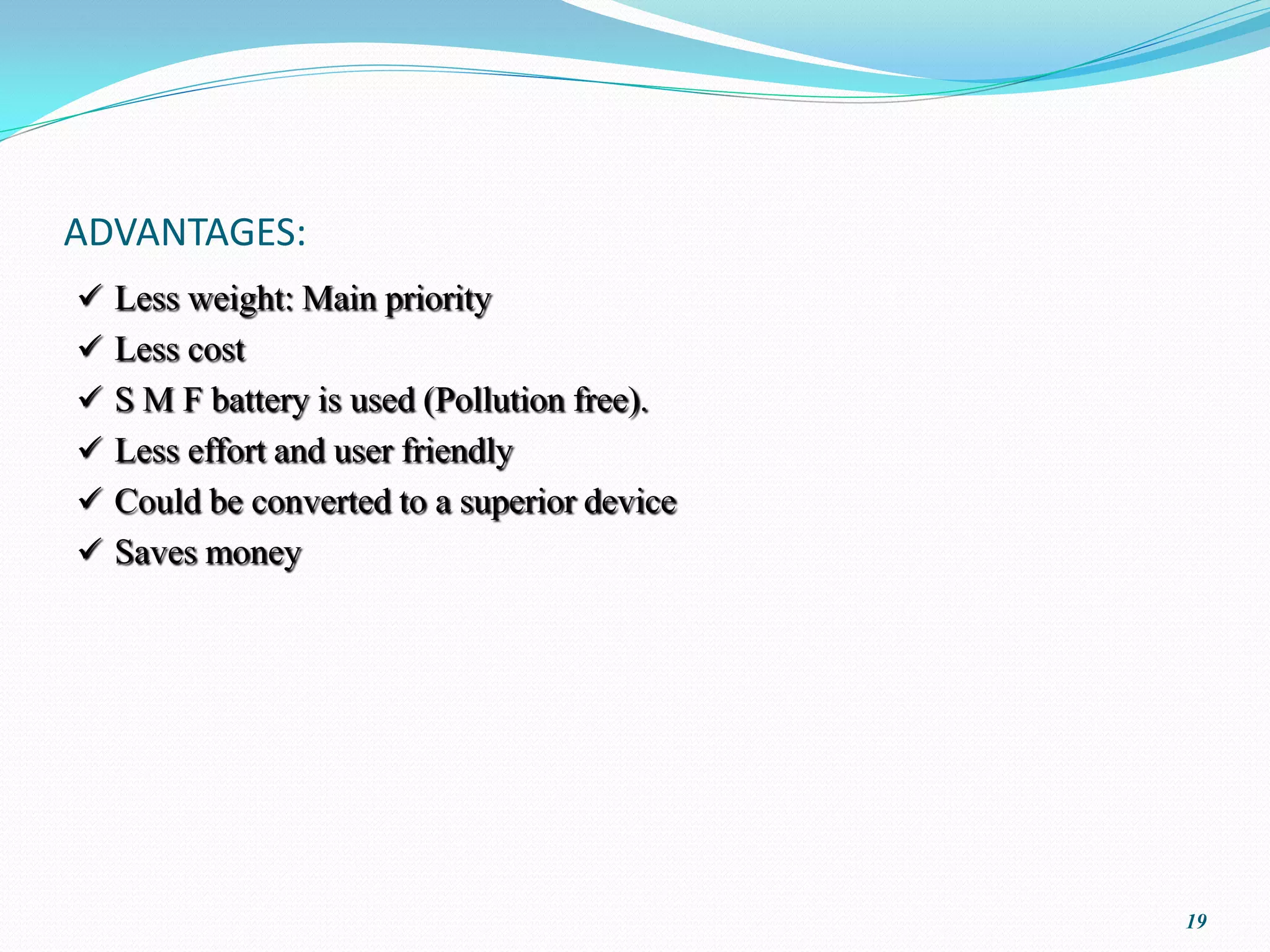
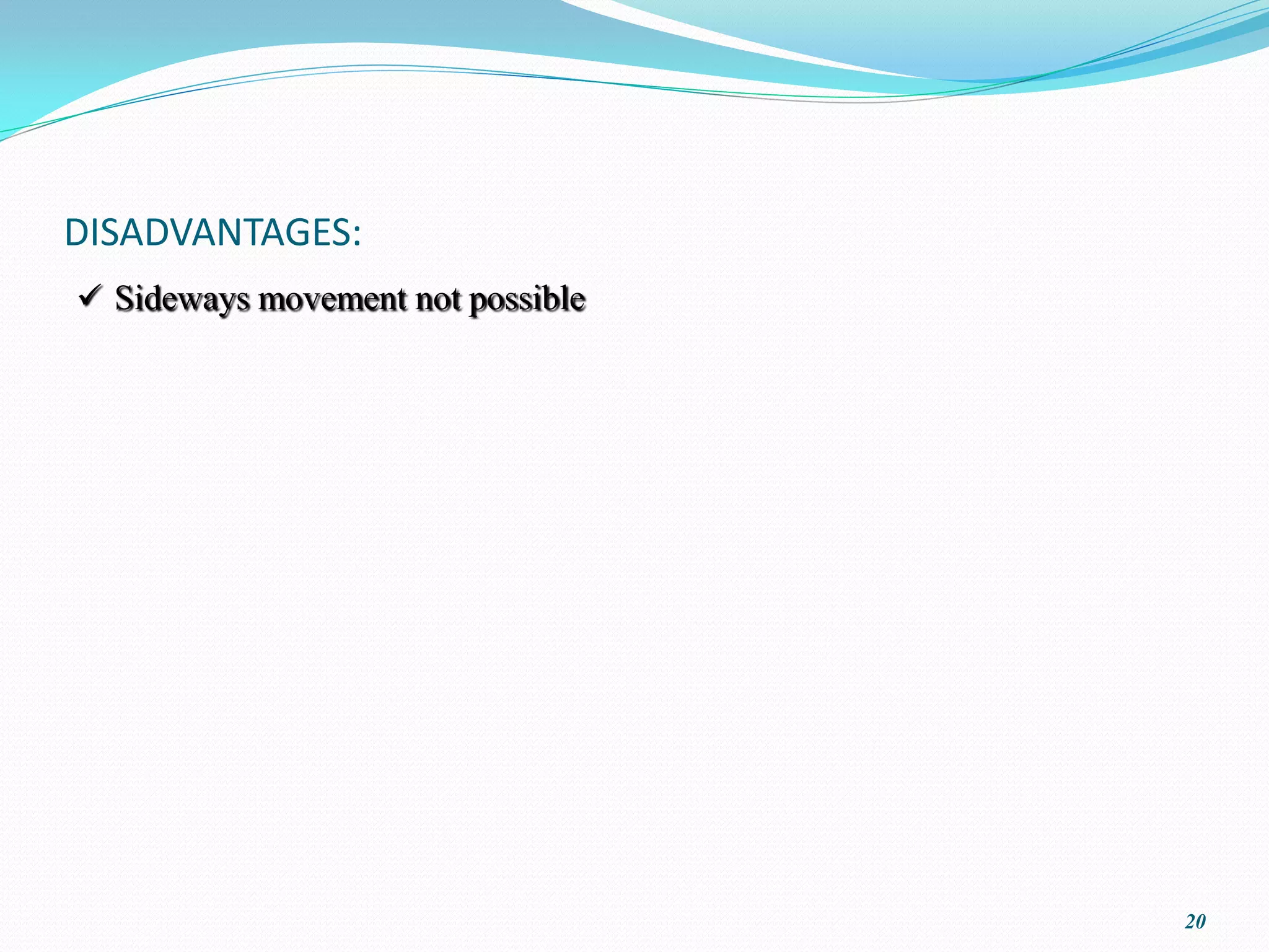
TREE TRUNK CLIMBING DEVICE


              shazmr369gmail.com


                                   1
PROJECT GOALS:
    ABSTRACT
             The objective of this project is to construct a remote controlled
    device that can move up and down on a tree trunk which can thus enable
    various further applications in future which will be useful to man in various
    ways.



                                                                                    2
BLOCK DIAGRAM:

     BATTERY      BATTERY


                   DC       CLIMBING
     RF
                 SERIES       UNIT
   MODULE
                 MOTORS


                                       3
WORKING COMPONENTS:
   RF module with a battery
   DC series motors with battery
   Climbing unit with spring loaded wheels


                                              4
RF MODULE:
 Radio frequency is an electromagnetic wave frequency between the audio
    and infrared.
   Its in the range 30kHz to 300GHz.
   It corresponds to the frequency of electrical signals normally used to
    produce and detect radio waves.
   RF unit used is of the capacity 40MHz.
   The unit is taken from a toy car.
   In order to increase its range an Ariel is used.
   RF unit is of 2 components: RF TRANSMITTER,
                                   RF RECIEVER.


                                                                             5
RF TRANSMITTER:
 RF transmitter is to modulate, up convert, and amplify signals for
  transmission into free space. An RF transmitter generally includes a
  modulator that modulates an input signal and a radio frequency power
  amplifier that is coupled to the modulator to amplify the modulated input
  signal. The radio frequency power amplifier is coupled to an antenna that
  transmits the amplified modulated input signal. Power amplifiers are
  required in radio telecommunication systems to amplify signals before
  transmitting, because a radio signal attenuates on the radio path. For
  efficiency, the amplifier is often a non-linear amplifier operated near its
  peak capacity.
 RF receiver holds the job of receiving the modulated signal and then
  demodulating the particular signal to output signal; thus giving instructions
  to the exterior on accordance to it.

                                                                                  6
BATTERY:
 S M F Battery is being used here.
 Its capacity is featured as: 12V, 7Ah.


                                           7
DC SERIES MOTORS:
 Total no of motors    :2
 Total capacity        : 28W
 Distributed as        : (14+14)W
 Motor rpm determines the wheel diameter


                                            8
CLIMBING UNIT:
 2 separate spring loaded wheels
 Spring pressurizes the unit to the tree
 Spring adjusts the unit according to the varying diameter of the tree
 Pipes employed at either parts of the unit to avoid path difference
 Chassis for further attachments
 Chassis also has RF module, 2 motors,1 battery etc.


                                                                          9
OPERATION PROCEDURE:

BATTERY           RF MODULE


BATTERY           DC MOTORS

                       VIA SHAFTS


                  WHEELS


                                    10
STRUCTURE LAYOUT:

                    B
                                RFR


 S                              S

             M


                            M

                    R F T
COMPONENT IMAGES:
 WIPER MOTOR

: 14W
  12V
  44 rpm





           FIG NO:01
                       12
 SPRING

Mean diameter of coils, D
                                 :24mm
Wire diameter, d                 :2mm
No. of coils, n                  :85
Spacing index, c                 :D/d
                                 =12
Stiffness, k   :F/ defl.
                             =G(d)^4/8(D^3)n
                                 =1.24N/mm


                FIG NO: 02


                                               13
 WHEELS

Diameter of wheels,
        d: 6mm


            FIG NO: 03


                         14
RF TRANSMITTER & RECEIVER:
CALCULATIONS INVOLVED:
    Total mass estimated, m               : 10 kg
    Total height estimated, h             : 20m.
    Battery capacity                      : 12V, 7AH
    Motor capacity                : 12V,14W,44rpm.
    Total watt used                       = 14*(no. of motors used)
                                           = 28W.
  Due to 50% of loss assumed              = 28/2
                                           = 14W.
  For the height and weight mentioned
   time taken, t                           = (746*h*m)/(W*75)
                                           = 2.5 mins (app.).


                                                                       16
 Total rpm                  = 44*2.5
                             = 110 rpm.

        110 rpm                  20m
           1 rpm                 18cm (app.)
 Diameter of the wheel, d   :

                  (3.14*d)   = 18
                         d   = 6 cm (app.)


                                               17
COMPETITIVE ANALYSIS:
 Strength:
    Less weight: Main priority
    Less effort and user friendly


                                    18
ADVANTAGES:
 Less weight: Main priority
 Less cost
 S M F battery is used (Pollution free).
 Less effort and user friendly
 Could be converted to a superior device
 Saves money


                                            19
DISADVANTAGES:
 Sideways movement not possible


                                   20
REFERENCES:
  Design of Machine Elements   : KHURUMI

  Design Data                  : PSG College of Technology,
                                                 COIMBATORE
Tree trunk climbing device

Tree trunk climbing device

  • 1.
    TREE TRUNK CLIMBINGDEVICE shazmr369gmail.com 1
  • 2.
    PROJECT GOALS: ABSTRACT  The objective of this project is to construct a remote controlled device that can move up and down on a tree trunk which can thus enable various further applications in future which will be useful to man in various ways.  2
  • 3.
    BLOCK DIAGRAM: BATTERY BATTERY DC CLIMBING RF SERIES UNIT MODULE MOTORS 3
  • 4.
    WORKING COMPONENTS:  RF module with a battery  DC series motors with battery  Climbing unit with spring loaded wheels 4
  • 5.
    RF MODULE:  Radiofrequency is an electromagnetic wave frequency between the audio and infrared.  Its in the range 30kHz to 300GHz.  It corresponds to the frequency of electrical signals normally used to produce and detect radio waves.  RF unit used is of the capacity 40MHz.  The unit is taken from a toy car.  In order to increase its range an Ariel is used.  RF unit is of 2 components: RF TRANSMITTER, RF RECIEVER. 5
  • 6.
    RF TRANSMITTER:  RFtransmitter is to modulate, up convert, and amplify signals for transmission into free space. An RF transmitter generally includes a modulator that modulates an input signal and a radio frequency power amplifier that is coupled to the modulator to amplify the modulated input signal. The radio frequency power amplifier is coupled to an antenna that transmits the amplified modulated input signal. Power amplifiers are required in radio telecommunication systems to amplify signals before transmitting, because a radio signal attenuates on the radio path. For efficiency, the amplifier is often a non-linear amplifier operated near its peak capacity.  RF receiver holds the job of receiving the modulated signal and then demodulating the particular signal to output signal; thus giving instructions to the exterior on accordance to it. 6
  • 7.
    BATTERY:  S MF Battery is being used here.  Its capacity is featured as: 12V, 7Ah. 7
  • 8.
    DC SERIES MOTORS: Total no of motors :2  Total capacity : 28W  Distributed as : (14+14)W  Motor rpm determines the wheel diameter 8
  • 9.
    CLIMBING UNIT:  2separate spring loaded wheels  Spring pressurizes the unit to the tree  Spring adjusts the unit according to the varying diameter of the tree  Pipes employed at either parts of the unit to avoid path difference  Chassis for further attachments  Chassis also has RF module, 2 motors,1 battery etc. 9
  • 10.
    OPERATION PROCEDURE: BATTERY RF MODULE BATTERY DC MOTORS VIA SHAFTS WHEELS 10
  • 11.
    STRUCTURE LAYOUT: B RFR S S M M R F T
  • 12.
    COMPONENT IMAGES:  WIPERMOTOR : 14W 12V 44 rpm  FIG NO:01 12
  • 13.
     SPRING Mean diameterof coils, D :24mm Wire diameter, d :2mm No. of coils, n :85 Spacing index, c :D/d =12 Stiffness, k :F/ defl. =G(d)^4/8(D^3)n =1.24N/mm FIG NO: 02 13
  • 14.
     WHEELS Diameter ofwheels, d: 6mm FIG NO: 03 14
  • 15.
  • 16.
    CALCULATIONS INVOLVED:  Total mass estimated, m : 10 kg  Total height estimated, h : 20m.  Battery capacity : 12V, 7AH  Motor capacity : 12V,14W,44rpm.  Total watt used = 14*(no. of motors used) = 28W.  Due to 50% of loss assumed = 28/2 = 14W.  For the height and weight mentioned time taken, t = (746*h*m)/(W*75) = 2.5 mins (app.). 16
  • 17.
     Total rpm = 44*2.5 = 110 rpm. 110 rpm 20m 1 rpm 18cm (app.)  Diameter of the wheel, d : (3.14*d) = 18 d = 6 cm (app.) 17
  • 18.
    COMPETITIVE ANALYSIS:  Strength: Less weight: Main priority Less effort and user friendly 18
  • 19.
    ADVANTAGES:  Less weight:Main priority  Less cost  S M F battery is used (Pollution free).  Less effort and user friendly  Could be converted to a superior device  Saves money 19
  • 20.
  • 21.
    REFERENCES: Designof Machine Elements : KHURUMI Design Data : PSG College of Technology, COIMBATORE