Downloaded 490 times

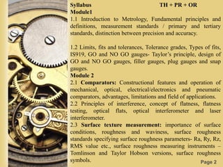
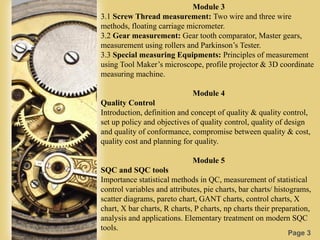


This document discusses metrology, which is the science of measurement. It covers key concepts in metrology including standards of measurement, accuracy vs precision, limits, fits and tolerances. The document is divided into six modules which cover topics such as comparison measurement tools, screw thread and gear measurement, quality control principles, and statistical process control tools. Measurement standards including line, end, and wavelength standards are explained. International tolerance grades and limits of size are also summarized.