Download to read offline


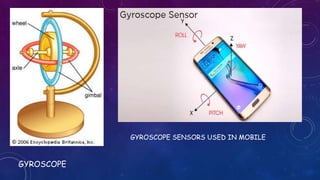


A gyroscope is a device that uses the conservation of angular momentum to detect changes in orientation and maintain stability. It consists of a spinning wheel or disc mounted in gimbals to allow free movement. When spinning, the axis of rotation remains fixed in space regardless of tilting or rotation of the mounting. Gyroscopes are used in navigation systems to maintain orientation and measure angular velocity. They operate based on the principle that a spinning mass tends to resist changes to its axis of rotation.


