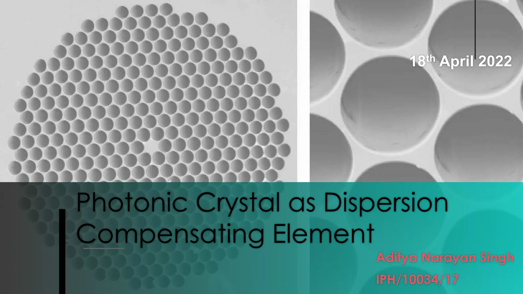
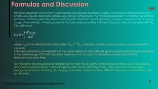
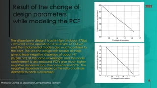
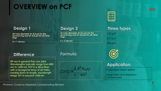
Photonic Crystal as Dispersion
Compensating Element
Aditya Narayan Singh
IPH/10034/17
18th April 2022
Photonic crystal fibers (PCFs) consisting of a central
defect region surrounded by multiple air holes that
run along the fiber length are attracting much
attention in recent years because of unique
properties which are not realized in conventional
optical fibers. PCFs are divided into two different kinds
of fibers. The first one, index-guiding PCF, guides light
by total internal reflection between a solid core and
a cladding region with multiple air-holes. Dispersion is
the major limiting factor for the data rate of an
optical fiber link. Present day dense wavelength
division multiplexing (WDM) networks need very
stringent dispersion management criteria. Within the
two decades of commercial deployment of optical
fiber links, dispersion phenomenon is well understood
and different methods for combating the pulse
spreading due to dispersion are developed. In the
recent years, a special class of optical fibers known as
photonic crystal fibers (PCF) is widely being explored
for its dispersion compensating properties. These are
of three types.
Photonic Crystal as Dispersion Compensating Element 2
2022
Standard Fiber and Photonic Crystal Fiber
Standard Index Fiber (SIF)
An optical fiber is a cylindrical dielectric waveguide
(nonconducting waveguide) that transmits light along
its axis through the process of total internal reflection.
The fiber consists of a core surrounded by a cladding layer,
both of which are made of dielectric materials. In general
they are solid, Wavelengths typically range from 800 nm to
1600 nm.
Photonic Crystal Fiber (PCF)
Photonic Crystal as Dispersion Compensating Element
3
2022
The PCF is a silica fiber with a hexagonal array of air
holes running down its length. It is particularly
interesting from a waveguiding point of view,
because it shows properties that are very different
from standard optical fibers, including single-mode
operation in a wavelength range from 337 nm to
beyond 1550 nm
DISPERSION COMPENSATION
Photonic Crystal as Dispersion Compensating Element
4
To compensate for the large positive dispersion with
a much shorter fiber length, a DCF needs to have
very high negative dispersion. Typical ratio of
communication fiber length to DCF length is around
6 : 7. Several designs of DCFs in order to provide
large negative dispersion have been suggested. The
refractive index profile of DCFs is changed in order
to obtain high waveguide dispersion. The
subsequent doping increases the insertion loss
2022
The air hole diameters are, d= 0.5 µm for the second ring and
d= 0.8 µm for all other rings as in design . The cladding consists
of five concentric rings of air holes arranged in a triangular
array within a pure silica base of refractive index 1.45. The
absence of the central hole forms the core. These parameters
are common for both design, for first design we have Л = 1
micron and for second 2 micron.
Formulas and Discussion
Photonic Crystal as Dispersion Compensating Element
5
2022
The total dispersion comes from material and waveguide dispersion. Unlike conventional fibers the photonic
crystal waveguide dispersion can be very strong. Furthermore, the “material dispersion” is modified by artificial
photonic cladding with the presence of air-holes. Photonic crystal cladding changes massively over a narrow
range of wavelength. A key parameter that describes properties of fibers is a group velocity dispersion (GVD).
It is defined as:
GVD =
𝜆
𝑐
ⅆ2𝑛𝑒𝑓𝑓
ⅆ𝜆2
where neff is the effective refraction index neff = 𝛽
𝑘0
where β is phase constant and k0 is wave number in
vacuum.
If the zero-dispersion wavelength is in the visible region, it automatically gives a positive (anomalous) dispersion
in the visible range. PCF with a positive dispersion can be used for dispersion compensation in the
telecommunication lines.
To overcome this drawback central part of the core has a slightly higher refractive index due to Ge-doping
and is surrounded by three F-doped regions with a lower refractive index . The core is surrounded with
hexagonal photonic cladding. By varying parameters of the structure, different dispersion characteristics are
achievable.
Result of the change of
design parameters
while modeling the PCF
The dispersion in design1 is quite high at about -775ps
/ (km.nm) at the operating wave length of 1.55 µm
and the fundamental mode is also much confined to
the core. The second design with smaller air holes
gives a lesser negative dispersion of about -47
ps/(km.nm) at the same wavelength and the mode
confinement is also reduced. PCFs give much higher
negative dispersion than the conventional DCFs. The
negative dispersion increases as the ratio of air hole
diameter to pitch is increased.
Photonic Crystal as Dispersion Compensating Element
6
2022
OVERVIEW on PCF
Design 1
Photonic Crystal as Dispersion Compensating Element
7
2022
Design 2 Three types
Application
Formula
Difference
Air hole diameter d= 0.5 µm for the
second ring and d= 0.8 µm for all other
rings
Л = 1 micron
Air hole diameter d= 0.5 µm for the
second ring and d= 0.8 µm for all other
rings
Л = 2 micron
1-D pcf
2-D pcf
3-D pcf
SIF are In general they are solid,
Wavelengths typically range from 800
nm to 1600 nm. PCF is a silica fiber
with a hexagonal array of air holes
running down its length, wavelength
range 337 to beyond 1550 nm
GVD =
𝜆
𝑐
ⅆ2𝑛𝑒𝑓𝑓
ⅆ𝜆2
Polarization beam splitter
Super prism and dispersion
compensator
THANK YOU!
ADITYA NARAYAN SINGH
2022
1. https://doi.org/10.1145/1523103.1523148
2. https://www.osapublishing.org/abstract.cfm?uri=oe-11-8-843
3. https://en.wikipedia.org/wiki/Photonic-crystal_fiber
4. http://przyrbwn.icm.edu.pl/APP/PDF/106/a106z216.pdf
5. Class notes
6. https://www.rp-photonics.com/effective_refractive_index.html

Photonic Crystal as Dispersion Compensating Element.pptx

  • 1.
    Photonic Crystal asDispersion Compensating Element Aditya Narayan Singh IPH/10034/17 18th April 2022
  • 2.
    Photonic crystal fibers(PCFs) consisting of a central defect region surrounded by multiple air holes that run along the fiber length are attracting much attention in recent years because of unique properties which are not realized in conventional optical fibers. PCFs are divided into two different kinds of fibers. The first one, index-guiding PCF, guides light by total internal reflection between a solid core and a cladding region with multiple air-holes. Dispersion is the major limiting factor for the data rate of an optical fiber link. Present day dense wavelength division multiplexing (WDM) networks need very stringent dispersion management criteria. Within the two decades of commercial deployment of optical fiber links, dispersion phenomenon is well understood and different methods for combating the pulse spreading due to dispersion are developed. In the recent years, a special class of optical fibers known as photonic crystal fibers (PCF) is widely being explored for its dispersion compensating properties. These are of three types. Photonic Crystal as Dispersion Compensating Element 2 2022
  • 3.
    Standard Fiber andPhotonic Crystal Fiber Standard Index Fiber (SIF) An optical fiber is a cylindrical dielectric waveguide (nonconducting waveguide) that transmits light along its axis through the process of total internal reflection. The fiber consists of a core surrounded by a cladding layer, both of which are made of dielectric materials. In general they are solid, Wavelengths typically range from 800 nm to 1600 nm. Photonic Crystal Fiber (PCF) Photonic Crystal as Dispersion Compensating Element 3 2022 The PCF is a silica fiber with a hexagonal array of air holes running down its length. It is particularly interesting from a waveguiding point of view, because it shows properties that are very different from standard optical fibers, including single-mode operation in a wavelength range from 337 nm to beyond 1550 nm
  • 4.
    DISPERSION COMPENSATION Photonic Crystalas Dispersion Compensating Element 4 To compensate for the large positive dispersion with a much shorter fiber length, a DCF needs to have very high negative dispersion. Typical ratio of communication fiber length to DCF length is around 6 : 7. Several designs of DCFs in order to provide large negative dispersion have been suggested. The refractive index profile of DCFs is changed in order to obtain high waveguide dispersion. The subsequent doping increases the insertion loss 2022 The air hole diameters are, d= 0.5 µm for the second ring and d= 0.8 µm for all other rings as in design . The cladding consists of five concentric rings of air holes arranged in a triangular array within a pure silica base of refractive index 1.45. The absence of the central hole forms the core. These parameters are common for both design, for first design we have Л = 1 micron and for second 2 micron.
  • 5.
    Formulas and Discussion PhotonicCrystal as Dispersion Compensating Element 5 2022 The total dispersion comes from material and waveguide dispersion. Unlike conventional fibers the photonic crystal waveguide dispersion can be very strong. Furthermore, the “material dispersion” is modified by artificial photonic cladding with the presence of air-holes. Photonic crystal cladding changes massively over a narrow range of wavelength. A key parameter that describes properties of fibers is a group velocity dispersion (GVD). It is defined as: GVD = 𝜆 𝑐 ⅆ2𝑛𝑒𝑓𝑓 ⅆ𝜆2 where neff is the effective refraction index neff = 𝛽 𝑘0 where β is phase constant and k0 is wave number in vacuum. If the zero-dispersion wavelength is in the visible region, it automatically gives a positive (anomalous) dispersion in the visible range. PCF with a positive dispersion can be used for dispersion compensation in the telecommunication lines. To overcome this drawback central part of the core has a slightly higher refractive index due to Ge-doping and is surrounded by three F-doped regions with a lower refractive index . The core is surrounded with hexagonal photonic cladding. By varying parameters of the structure, different dispersion characteristics are achievable.
  • 6.
    Result of thechange of design parameters while modeling the PCF The dispersion in design1 is quite high at about -775ps / (km.nm) at the operating wave length of 1.55 µm and the fundamental mode is also much confined to the core. The second design with smaller air holes gives a lesser negative dispersion of about -47 ps/(km.nm) at the same wavelength and the mode confinement is also reduced. PCFs give much higher negative dispersion than the conventional DCFs. The negative dispersion increases as the ratio of air hole diameter to pitch is increased. Photonic Crystal as Dispersion Compensating Element 6 2022
  • 7.
    OVERVIEW on PCF Design1 Photonic Crystal as Dispersion Compensating Element 7 2022 Design 2 Three types Application Formula Difference Air hole diameter d= 0.5 µm for the second ring and d= 0.8 µm for all other rings Л = 1 micron Air hole diameter d= 0.5 µm for the second ring and d= 0.8 µm for all other rings Л = 2 micron 1-D pcf 2-D pcf 3-D pcf SIF are In general they are solid, Wavelengths typically range from 800 nm to 1600 nm. PCF is a silica fiber with a hexagonal array of air holes running down its length, wavelength range 337 to beyond 1550 nm GVD = 𝜆 𝑐 ⅆ2𝑛𝑒𝑓𝑓 ⅆ𝜆2 Polarization beam splitter Super prism and dispersion compensator
  • 8.
    THANK YOU! ADITYA NARAYANSINGH 2022 1. https://doi.org/10.1145/1523103.1523148 2. https://www.osapublishing.org/abstract.cfm?uri=oe-11-8-843 3. https://en.wikipedia.org/wiki/Photonic-crystal_fiber 4. http://przyrbwn.icm.edu.pl/APP/PDF/106/a106z216.pdf 5. Class notes 6. https://www.rp-photonics.com/effective_refractive_index.html