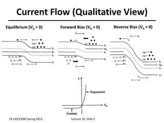
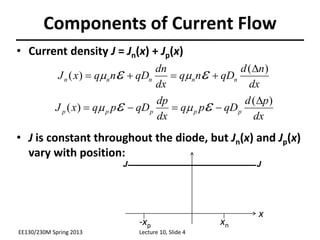
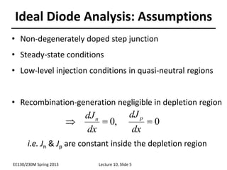
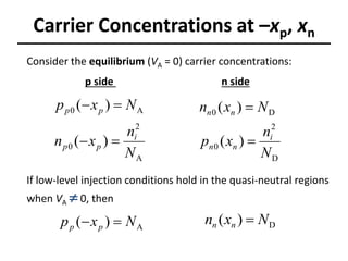
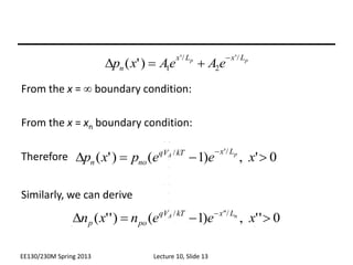
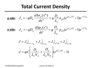
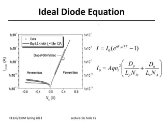
Lecture 10
OUTLINE
• pn Junction Diodes (cont’d)
– Derivation of the Ideal Diode
Equation (for a step junction)
Reading: Pierret 6.1; Hu 4.3, 4.6, 4.8-4.9
Current Flow (Qualitative View)
EE130/230M Spring 2013 Lecture 10, Slide 2
Equilibrium (VA = 0) Forward Bias (VA > 0) Reverse Bias (VA < 0)
Minority Carrier Action
under Forward Bias
• When a forward bias (VA>0) is applied, the potential
barrier to diffusion across the junction is reduced
– Minority carriers are “injected” into the quasi-neutral
regions => Dnp > 0, Dpn > 0
• Minority carriers diffuse in the quasi-neutral regions,
recombining with majority carriers
EE130/230M Spring 2013 Lecture 10, Slide 3
Components of Current Flow
• Current density J = Jn(x) + Jp(x)
• J is constant throughout the diode, but Jn(x) and Jp(x)
vary with position:
dx
n
d
qD
n
q
dx
dn
qD
n
q
x
J n
n
n
n
n
)
(
)
(
D



 
 

dx
p
d
qD
p
q
dx
dp
qD
p
q
x
J p
p
p
p
p
)
(
)
(
D



 
 

EE130/230M Spring 2013 Lecture 10, Slide 4
x
xn
-xp
J
J
Ideal Diode Analysis: Assumptions
• Non-degenerately doped step junction
• Steady-state conditions
• Low-level injection conditions in quasi-neutral regions
• Recombination-generation negligible in depletion region
i.e. Jn & Jp are constant inside the depletion region
0
,
0 


dx
dJ
dx
dJ p
n
EE130/230M Spring 2013 Lecture 10, Slide 5
“Game Plan” for Obtaining Diode I-V
1. Solve minority-carrier diffusion equations in quasi-neutral
regions to obtain excess carrier distributions Dnp(x,VA),Dpn(x,VA)
– boundary conditions:
• p side: Dnp(-xp), Dnp(-)
• n side: Dpn(xn), Dpn()
2. Find minority-carrier current densities in quasi-neutral regions
3. Evaluate Jn at x=-xp & Jp at x=xn to obtain total current density J:
dx
n
d
qD
V
x
J p
n
A
n
)
(
)
,
(
D

dx
p
d
qD
V
x
J n
p
A
p
)
(
)
,
(
D


EE130/230M Spring 2013 Lecture 10, Slide 6
)
,
(
)
,
(
)
( A
n
p
A
p
n
A V
x
J
V
x
J
V
J 


Carrier Concentrations at –xp, xn
n side
p side
Consider the equilibrium (VA = 0) carrier concentrations:
A
2
0
A
0
)
(
)
(
N
n
x
n
N
x
p
i
p
p
p
p




D
2
0
D
0
)
(
)
(
N
n
x
p
N
x
n
i
n
n
n
n


If low-level injection conditions hold in the quasi-neutral regions
when VA  0, then
A
)
( N
x
p p
p 
 D
)
( N
x
n n
n 
“Law of the Junction”
The voltage applied to a pn junction falls mostly across the depletion
region (assuming low-level injection in the quasi-neutral regions).
We can draw 2 quasi-Fermi levels in the depletion region:
kT
E
F
e
n
n /
)
(
i
i
N 

kT
F
E
e
n
p /
)
(
i
P
i 

kT
qV
e
n
pn /
2
i
A

kT
F
F P
N
e
n
pn /
)
(
2
i


EE130/230M Spring 2013 Lecture 10, Slide 8
Excess Carrier Concentrations at –xp, xn
 
1
)
(
)
(
)
(
/
A
2
/
0
A
/
2
A
A
A
A



D





kT
qV
i
p
p
kT
qV
p
kT
qV
i
p
p
p
p
e
N
n
x
n
e
n
N
e
n
x
n
N
x
p
n side
p side
 
1
)
(
)
(
)
(
/
D
2
/
0
D
/
2
D
A
A
A


D



kT
qV
i
n
n
kT
qV
n
kT
qV
i
n
n
n
n
e
N
n
x
p
e
p
N
e
n
x
p
N
x
n
EE130/230M Spring 2013 Lecture 10, Slide 9
Carrier Concentration Profiles
under Forward Bias
EE130/230M Spring 2013 Lecture 10, Slide 10
Example
Consider a pn junction with NA=1018 cm-3 and ND=1016 cm-3,
under a forward bias of 0.6 V.
EE130/230M Spring 2013 Lecture 10, Slide 11
(a) What are the minority carrier concentrations at the edges
of the depletion region?
(b) What are the excess minority carrier concentrations at
the edges of the depletion region?
Excess Carrier Distribution (n side)
• From the minority carrier diffusion equation:
• We have the following boundary conditions:
• For simplicity, use a new coordinate system:
• Then, the solution is of the form:
0
)
( 

D n
p
)
1
(
)
( /


D kT
qV
no
n
n
A
e
p
x
p
2
2
2
p
n
p
p
n
n
L
p
D
p
dx
p
d D

D

D

p
p L
x
L
x
n e
A
e
A
x
p
/
'
2
/
'
1
)
'
(



D
NEW:
x’’ 0 0 x’
EE130/230M Spring 2013 Lecture 10, Slide 12
From the x =  boundary condition:
From the x = xn boundary condition:
Therefore
Similarly, we can derive
0
'
,
)
1
(
)
'
(
/
'
/



D

x
e
e
p
x
p p
A
L
x
kT
qV
no
n
p
p L
x
L
x
n e
A
e
A
x
p
/
'
2
/
'
1
)
'
(



D
0
'
'
,
)
1
(
)
'
'
( /
'
'
/



D 
x
e
e
n
x
n n
A L
x
kT
qV
po
p
EE130/230M Spring 2013 Lecture 10, Slide 13
Total Current Density
p
L
x
kT
V
q
n
p
p
n
p
p e
e
p
L
D
q
dx
x
p
d
qD
J
'
0 )
1
(
'
)
'
( A



D


n
L
x
kT
V
q
p
n
n
p
n
n e
e
n
L
D
q
dx
x
n
d
qD
J '
'
0 )
1
(
'
'
)
'
'
( A 


D


n side:
p side:
)
1
( A
D
A
2
i
0
0























kT
V
q
p
p
n
n
x
p
x
n
x
x
p
x
x
n
e
N
L
D
N
L
D
qn
J
J
J
J
J
J
n
p
EE130/230M Spring 2013 Lecture 10, Slide 14
Ideal Diode Equation
)
1
(
0 
 kT
V
q A
e
I
I










A
n
n
D
p
p
i
N
L
D
N
L
D
Aqn
I
2
0
EE130/230M Spring 2013 Lecture 10, Slide 15
Diode Saturation Current I0
• I0 can vary by orders of magnitude, depending on the
semiconductor material and dopant concentrations:
• In an asymmetrically doped (one-sided) pn junction, the term
associated with the more heavily doped side is negligible:
– If the p side is much more heavily doped,
– If the n side is much more heavily doped,










A
n
n
D
p
p
i
N
L
D
N
L
D
Aqn
I
2
0









D
p
p
i
N
L
D
Aqn
I
2
0









A
n
n
i
N
L
D
Aqn
I
2
0
EE130/230M Spring 2013 Lecture 10, Slide 16
• Depletion of minority carriers at edges of depletion region
• The only current which flows is due to drift of minority carriers
across the junction. This current is fed by diffusion of minority
carriers toward junction (supplied by thermal generation).
EE130/230M Spring 2013 Lecture 10, Slide 17
Carrier Concentration Profiles
under Reverse Bias
Alternative Derivation of Formula for I0
“Depletion approximation”:
• I0 is the rate at which carriers
are thermally generated within
one diffusion length of the
depletion region:
P
n
n
p
D
i
p
n
p
p
N
n
A
i
n
p
L
x
x
x
N
n
p
t
p
-x
x
-x
-L
N
n
n
t
n




D







D




/
/
2
2






















p
D
i
P
n
A
i
N
N
n
qAL
N
n
qAL
I


/
/
2
2
0
EE130/230M Spring 2013 Lecture 10, Slide 18
Summary
• Under forward bias (VA > 0), the potential barrier to carrier
diffusion is reduced  minority carriers are “injected” into the
quasi-neutral regions.
– The minority-carrier concentrations at the edges of the depletion region
change with the applied bias VA, by the factor
– The excess carrier concentrations in the quasi-neutral regions decay to
zero away from the depletion region, due to recombination.
pn junction diode current
• I0 can be viewed as the drift current due to minority carriers
generated within a diffusion length of the depletion region
kT
qVA
e /
EE130/230M Spring 2013 Lecture 10, Slide 19
)
1
( A
D
A
2
i 









 kT
V
q
p
p
n
n
e
N
L
D
N
L
D
qAn
I

Diode Equation.ppt

  • 1.
    Lecture 10 OUTLINE • pnJunction Diodes (cont’d) – Derivation of the Ideal Diode Equation (for a step junction) Reading: Pierret 6.1; Hu 4.3, 4.6, 4.8-4.9
  • 2.
    Current Flow (QualitativeView) EE130/230M Spring 2013 Lecture 10, Slide 2 Equilibrium (VA = 0) Forward Bias (VA > 0) Reverse Bias (VA < 0)
  • 3.
    Minority Carrier Action underForward Bias • When a forward bias (VA>0) is applied, the potential barrier to diffusion across the junction is reduced – Minority carriers are “injected” into the quasi-neutral regions => Dnp > 0, Dpn > 0 • Minority carriers diffuse in the quasi-neutral regions, recombining with majority carriers EE130/230M Spring 2013 Lecture 10, Slide 3
  • 4.
    Components of CurrentFlow • Current density J = Jn(x) + Jp(x) • J is constant throughout the diode, but Jn(x) and Jp(x) vary with position: dx n d qD n q dx dn qD n q x J n n n n n ) ( ) ( D         dx p d qD p q dx dp qD p q x J p p p p p ) ( ) ( D         EE130/230M Spring 2013 Lecture 10, Slide 4 x xn -xp J J
  • 5.
    Ideal Diode Analysis:Assumptions • Non-degenerately doped step junction • Steady-state conditions • Low-level injection conditions in quasi-neutral regions • Recombination-generation negligible in depletion region i.e. Jn & Jp are constant inside the depletion region 0 , 0    dx dJ dx dJ p n EE130/230M Spring 2013 Lecture 10, Slide 5
  • 6.
    “Game Plan” forObtaining Diode I-V 1. Solve minority-carrier diffusion equations in quasi-neutral regions to obtain excess carrier distributions Dnp(x,VA),Dpn(x,VA) – boundary conditions: • p side: Dnp(-xp), Dnp(-) • n side: Dpn(xn), Dpn() 2. Find minority-carrier current densities in quasi-neutral regions 3. Evaluate Jn at x=-xp & Jp at x=xn to obtain total current density J: dx n d qD V x J p n A n ) ( ) , ( D  dx p d qD V x J n p A p ) ( ) , ( D   EE130/230M Spring 2013 Lecture 10, Slide 6 ) , ( ) , ( ) ( A n p A p n A V x J V x J V J   
  • 7.
    Carrier Concentrations at–xp, xn n side p side Consider the equilibrium (VA = 0) carrier concentrations: A 2 0 A 0 ) ( ) ( N n x n N x p i p p p p     D 2 0 D 0 ) ( ) ( N n x p N x n i n n n n   If low-level injection conditions hold in the quasi-neutral regions when VA  0, then A ) ( N x p p p   D ) ( N x n n n 
  • 8.
    “Law of theJunction” The voltage applied to a pn junction falls mostly across the depletion region (assuming low-level injection in the quasi-neutral regions). We can draw 2 quasi-Fermi levels in the depletion region: kT E F e n n / ) ( i i N   kT F E e n p / ) ( i P i   kT qV e n pn / 2 i A  kT F F P N e n pn / ) ( 2 i   EE130/230M Spring 2013 Lecture 10, Slide 8
  • 9.
    Excess Carrier Concentrationsat –xp, xn   1 ) ( ) ( ) ( / A 2 / 0 A / 2 A A A A    D      kT qV i p p kT qV p kT qV i p p p p e N n x n e n N e n x n N x p n side p side   1 ) ( ) ( ) ( / D 2 / 0 D / 2 D A A A   D    kT qV i n n kT qV n kT qV i n n n n e N n x p e p N e n x p N x n EE130/230M Spring 2013 Lecture 10, Slide 9
  • 10.
    Carrier Concentration Profiles underForward Bias EE130/230M Spring 2013 Lecture 10, Slide 10
  • 11.
    Example Consider a pnjunction with NA=1018 cm-3 and ND=1016 cm-3, under a forward bias of 0.6 V. EE130/230M Spring 2013 Lecture 10, Slide 11 (a) What are the minority carrier concentrations at the edges of the depletion region? (b) What are the excess minority carrier concentrations at the edges of the depletion region?
  • 12.
    Excess Carrier Distribution(n side) • From the minority carrier diffusion equation: • We have the following boundary conditions: • For simplicity, use a new coordinate system: • Then, the solution is of the form: 0 ) (   D n p ) 1 ( ) ( /   D kT qV no n n A e p x p 2 2 2 p n p p n n L p D p dx p d D  D  D  p p L x L x n e A e A x p / ' 2 / ' 1 ) ' (    D NEW: x’’ 0 0 x’ EE130/230M Spring 2013 Lecture 10, Slide 12
  • 13.
    From the x=  boundary condition: From the x = xn boundary condition: Therefore Similarly, we can derive 0 ' , ) 1 ( ) ' ( / ' /    D  x e e p x p p A L x kT qV no n p p L x L x n e A e A x p / ' 2 / ' 1 ) ' (    D 0 ' ' , ) 1 ( ) ' ' ( / ' ' /    D  x e e n x n n A L x kT qV po p EE130/230M Spring 2013 Lecture 10, Slide 13
  • 14.
    Total Current Density p L x kT V q n p p n p pe e p L D q dx x p d qD J ' 0 ) 1 ( ' ) ' ( A    D   n L x kT V q p n n p n n e e n L D q dx x n d qD J ' ' 0 ) 1 ( ' ' ) ' ' ( A    D   n side: p side: ) 1 ( A D A 2 i 0 0                        kT V q p p n n x p x n x x p x x n e N L D N L D qn J J J J J J n p EE130/230M Spring 2013 Lecture 10, Slide 14
  • 15.
    Ideal Diode Equation ) 1 ( 0  kT V q A e I I           A n n D p p i N L D N L D Aqn I 2 0 EE130/230M Spring 2013 Lecture 10, Slide 15
  • 16.
    Diode Saturation CurrentI0 • I0 can vary by orders of magnitude, depending on the semiconductor material and dopant concentrations: • In an asymmetrically doped (one-sided) pn junction, the term associated with the more heavily doped side is negligible: – If the p side is much more heavily doped, – If the n side is much more heavily doped,           A n n D p p i N L D N L D Aqn I 2 0          D p p i N L D Aqn I 2 0          A n n i N L D Aqn I 2 0 EE130/230M Spring 2013 Lecture 10, Slide 16
  • 17.
    • Depletion ofminority carriers at edges of depletion region • The only current which flows is due to drift of minority carriers across the junction. This current is fed by diffusion of minority carriers toward junction (supplied by thermal generation). EE130/230M Spring 2013 Lecture 10, Slide 17 Carrier Concentration Profiles under Reverse Bias
  • 18.
    Alternative Derivation ofFormula for I0 “Depletion approximation”: • I0 is the rate at which carriers are thermally generated within one diffusion length of the depletion region: P n n p D i p n p p N n A i n p L x x x N n p t p -x x -x -L N n n t n     D        D     / / 2 2                       p D i P n A i N N n qAL N n qAL I   / / 2 2 0 EE130/230M Spring 2013 Lecture 10, Slide 18
  • 19.
    Summary • Under forwardbias (VA > 0), the potential barrier to carrier diffusion is reduced  minority carriers are “injected” into the quasi-neutral regions. – The minority-carrier concentrations at the edges of the depletion region change with the applied bias VA, by the factor – The excess carrier concentrations in the quasi-neutral regions decay to zero away from the depletion region, due to recombination. pn junction diode current • I0 can be viewed as the drift current due to minority carriers generated within a diffusion length of the depletion region kT qVA e / EE130/230M Spring 2013 Lecture 10, Slide 19 ) 1 ( A D A 2 i            kT V q p p n n e N L D N L D qAn I