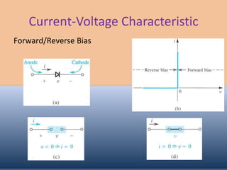
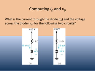
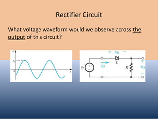
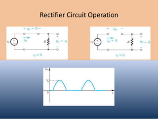
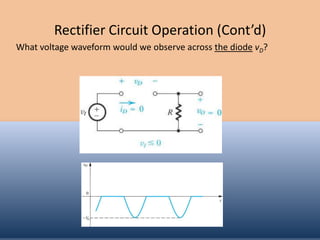
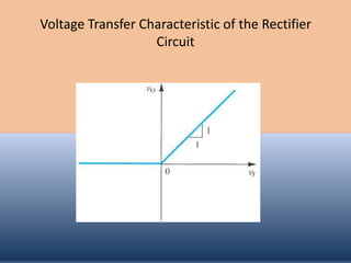
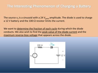
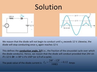
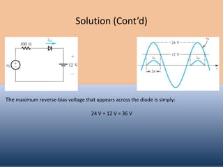
PRESENTATION TOPIC

IDEAL DIODE
SYED HASHIR AHMED
     ROLL# 130
Objectives
 Understand the characteristics of an ideal diode.

 Analyze simple circuits involving ideal diodes.
Current-Voltage Characteristic
Forward/Reverse Bias
Computing iD and vD

What is the current through the diode (iD) and the voltage
across the diode (vD) for the following two circuits?
Rectifier Circuit
What voltage waveform would we observe across the
output of this circuit?
Rectifier Circuit Operation
Rectifier Circuit Operation (Cont’d)
What voltage waveform would we observe across the diode vD?
Voltage Transfer Characteristic of the Rectifier
                   Circuit
The source vS is a sinusoid with a 24 Vpeak amplitude. The diode is used to charge
a 12 V battery and the 100 resistor limits the current.

We want to determine the fraction of each cycle during which the diode
conducts. We also wish to find the peak-value of the diode current and the
maximum reverse-bias voltage that appears across the diode.
Solution


We reason that the diode will not begin to conduct until vS exceeds 12 V. Likewise, the
diode will stop conducting once vS again reaches 12 V.

This defines the conduction angle, 2 (i.e., the fraction of the sinusoidal cycle over which
the diode conducts). Hence, we reason that the diode will conduct provided that 24V sin
    12 V. Or 30o ≤ ≤ 150o (or 1/3 of a cycle).
                                             24V 12V
The peak value of the diode current is I D                 0.12 Amps
                                               100
Solution (Cont’d)


The maximum reverse-bias voltage that appears across the diode is simply:

                                    24 V + 12 V = 36 V
Let’s begin by assuming that diodes D1 and D2 are conducting:

                10 0
         I D2        1mA
                10k

        KCL (node B):
                    0 ( 10)
         I 1mA                    I 1mA
                      5k


For this second circuit the same assumption gives
               nonsensical results (verify this) 

           We assume that D1 is OFF and D2 is ON.
               Consequently, VB = 3.3 V (verify).
FEEDBACK
syedhashir@ymail.com

Contect:03133116593

Diode by hashir ahmed