Download as PDF, PPTX
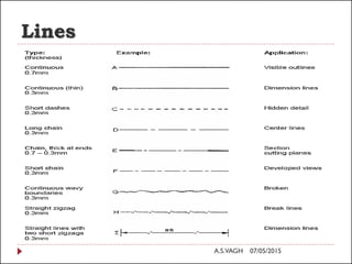


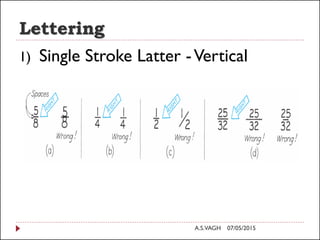
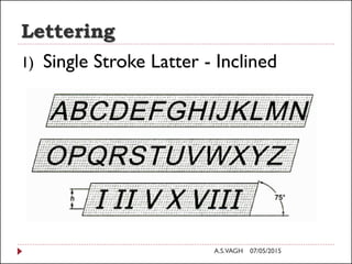


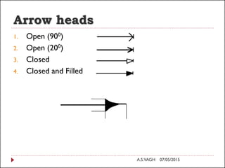
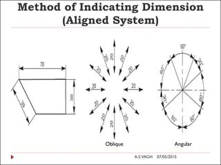


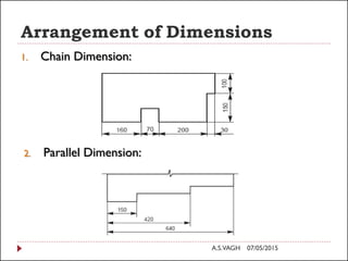

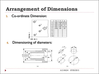

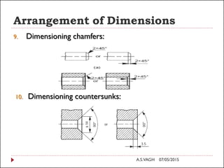


The document presents an overview of engineering graphics concepts including: 1) Types of lines used in technical drawings such as visible, hidden, center, and cutting plane lines. 2) Guidelines for lettering sizes and styles on drawings. 3) Methods for dimensioning drawings including terminology, arrowhead styles, and arrangement of dimensions. 4) Standards for technical drawings in India published by BIS in SP 46 for educational institutions. 5) A step-by-step process for drawing an ellipse using the concentric circle method.


![Attack surfaces and attack tress[inform]](https://cdn.slidesharecdn.com/ss_thumbnails/lecture03-260108015941-a4dee53b-thumbnail.jpg?width=640&height=640&fit=bounds)


