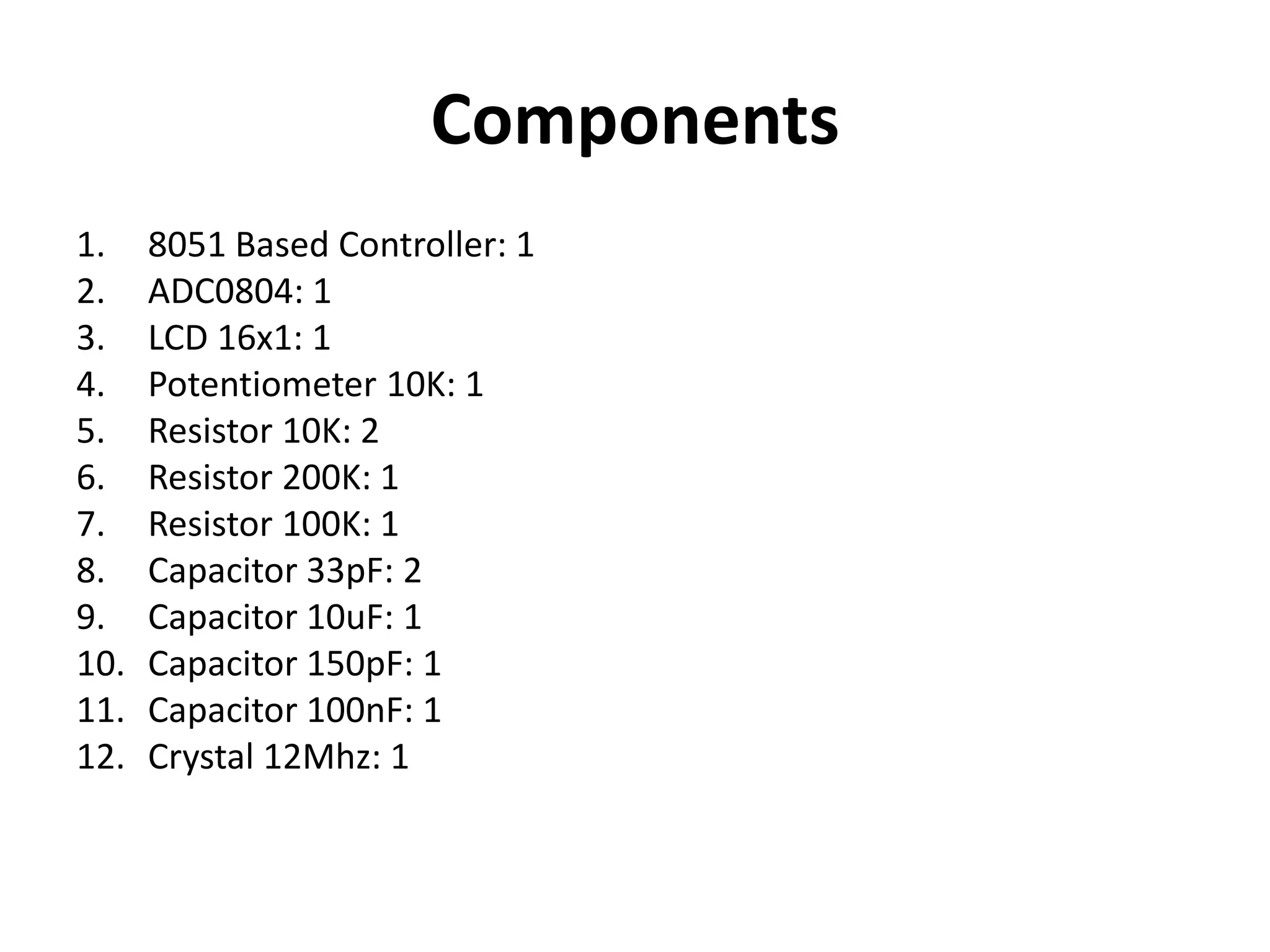
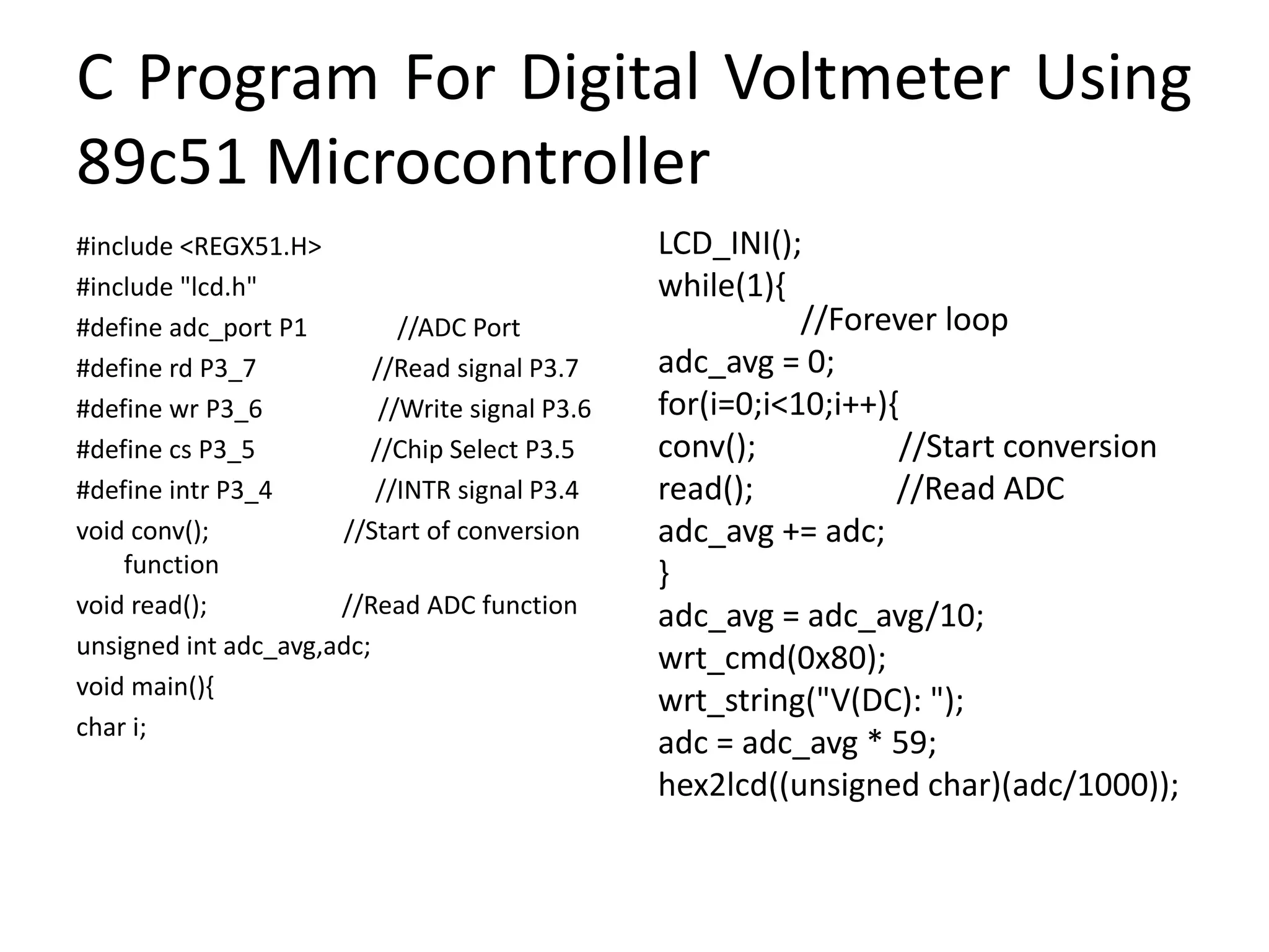
DIGITAL VOLTMETER USING
89C51 MICROCONTROLLER
Guide,
Prof. S. A. Karmude
By,
Saylee S. Joshi
INTRODUCTION
• Voltmeter is a voltage measuring instrument.
• We can measure the potential difference between any
two points in an electrical network using voltmeter.
• There are two types of voltmeter as analog voltmeter
and digital voltmeter.
• Analog voltmeter moves pointer on a scale but it has
some limitations like accuracy of few percent of full
scale.
• Digital voltmeter can display numerical value of voltage
on a display by use of analog to digital converter (ADC).
• All the data processing and manipulating is in digital
form, so it is very essential to use ADC.
Cont….
• We have used ADC0804 analog-to-digital
converter IC. The range of input voltage is 0-
15V. Here the input voltage should be DC
voltage so as to get the steady output on the
LCD display.
• If you give the AC voltage as an input, it will
display continuously running numbers as the
nature of AC voltage.
Block Diagram
Components Required For Digital
Voltmeter Using 89c51 Microcontroller
• Microcontroller, AT89C51
• Analog‐to‐Digital Converter, ADC0804
• 16×1 LCD
• Oscillator circuit for the microcontroller
– 12MHz Crystal Capacitor
– 33pF Capacitors
• Voltage divider circuit/ Input terminals
– 200k, 100k Resistors
– 100nF Capacitor
• ADC Clock Circuit 100k Potentiometer (to adjust the back‐light of
the LCD)
– 10k Resistor
– 150pF Capacitor
• 100k Potentiometer (to adjust the back‐light of the LCD)
Circuit Diagram Of Digital Voltmeter
Using 89c51 Microcontroller
Lcd Pin Diagram
Pin no. Name Description
1 Vss Ground
2 Vdd +5V
3 Vee Contrast Adjustment ‐2V to ‐5V
4 RS Register Select
5 RW 1 ‐Read , 0‐ Write
6 E Enable Strobe
7 D0 Data Line
8 D1 Data Line
9 D2 Data Line
10 D3 Data Line
11 D4 Data Line
12 D5 Data Line
13 D6 Data Line
14 D7 Data Line
15 LED+ Backlit LED +V Vdd (Optional signal)
16 LED‐ Backlit LED –V Vss (Optional signal)
Components
1. 8051 Based Controller: 1
2. ADC0804: 1
3. LCD 16x1: 1
4. Potentiometer 10K: 1
5. Resistor 10K: 2
6. Resistor 200K: 1
7. Resistor 100K: 1
8. Capacitor 33pF: 2
9. Capacitor 10uF: 1
10. Capacitor 150pF: 1
11. Capacitor 100nF: 1
12. Crystal 12Mhz: 1
C Program For Digital Voltmeter Using
89c51 Microcontroller
#include <REGX51.H>
#include "lcd.h"
#define adc_port P1 //ADC Port
#define rd P3_7 //Read signal P3.7
#define wr P3_6 //Write signal P3.6
#define cs P3_5 //Chip Select P3.5
#define intr P3_4 //INTR signal P3.4
void conv(); //Start of conversion
function
void read(); //Read ADC function
unsigned int adc_avg,adc;
void main(){
char i;
LCD_INI();
while(1){
//Forever loop
adc_avg = 0;
for(i=0;i<10;i++){
conv(); //Start conversion
read(); //Read ADC
adc_avg += adc;
}
adc_avg = adc_avg/10;
wrt_cmd(0x80);
wrt_string("V(DC): ");
adc = adc_avg * 59;
hex2lcd((unsigned char)(adc/1000));
Cont….
wrt_data('.');
adc = adc%1000;
hex2lcd((unsigned char)(adc/10));
wrt_data('V');
}
}
void conv(){
cs = 0; //Make CS low
wr = 0; //Make WR low
wr = 1; //Make WR high
cs = 1; //Make CS high
while(intr); //Wait for INTR to
go low
}
void read()
{
cs = 0; //Make CS low
rd = 0; //Make RD low
adc = adc_port; //Read ADC
port
rd = 1; //Make RD high
cs = 1; //Make CS high
}
Advantages
• This system is used to measure the voltage in
low voltage applications.
• Used to measure the toy batteries.
• We can measure the physical quantities like
temperature, humidity, gas etc. using this
system with a little modification.
disadvantages
• The input analog voltage range should be 0 to
5V.
• Using this system we can measure only one
analog input value at a time.
Digital voltmeter using 89c51 microcontroller

Digital voltmeter using 89c51 microcontroller

  • 1.
    DIGITAL VOLTMETER USING 89C51MICROCONTROLLER Guide, Prof. S. A. Karmude By, Saylee S. Joshi
  • 2.
    INTRODUCTION • Voltmeter isa voltage measuring instrument. • We can measure the potential difference between any two points in an electrical network using voltmeter. • There are two types of voltmeter as analog voltmeter and digital voltmeter. • Analog voltmeter moves pointer on a scale but it has some limitations like accuracy of few percent of full scale. • Digital voltmeter can display numerical value of voltage on a display by use of analog to digital converter (ADC). • All the data processing and manipulating is in digital form, so it is very essential to use ADC.
  • 3.
    Cont…. • We haveused ADC0804 analog-to-digital converter IC. The range of input voltage is 0- 15V. Here the input voltage should be DC voltage so as to get the steady output on the LCD display. • If you give the AC voltage as an input, it will display continuously running numbers as the nature of AC voltage.
  • 4.
  • 5.
    Components Required ForDigital Voltmeter Using 89c51 Microcontroller • Microcontroller, AT89C51 • Analog‐to‐Digital Converter, ADC0804 • 16×1 LCD • Oscillator circuit for the microcontroller – 12MHz Crystal Capacitor – 33pF Capacitors • Voltage divider circuit/ Input terminals – 200k, 100k Resistors – 100nF Capacitor • ADC Clock Circuit 100k Potentiometer (to adjust the back‐light of the LCD) – 10k Resistor – 150pF Capacitor • 100k Potentiometer (to adjust the back‐light of the LCD)
  • 6.
    Circuit Diagram OfDigital Voltmeter Using 89c51 Microcontroller
  • 7.
    Lcd Pin Diagram Pinno. Name Description 1 Vss Ground 2 Vdd +5V 3 Vee Contrast Adjustment ‐2V to ‐5V 4 RS Register Select 5 RW 1 ‐Read , 0‐ Write 6 E Enable Strobe 7 D0 Data Line 8 D1 Data Line 9 D2 Data Line 10 D3 Data Line 11 D4 Data Line 12 D5 Data Line 13 D6 Data Line 14 D7 Data Line 15 LED+ Backlit LED +V Vdd (Optional signal) 16 LED‐ Backlit LED –V Vss (Optional signal)
  • 8.
    Components 1. 8051 BasedController: 1 2. ADC0804: 1 3. LCD 16x1: 1 4. Potentiometer 10K: 1 5. Resistor 10K: 2 6. Resistor 200K: 1 7. Resistor 100K: 1 8. Capacitor 33pF: 2 9. Capacitor 10uF: 1 10. Capacitor 150pF: 1 11. Capacitor 100nF: 1 12. Crystal 12Mhz: 1
  • 9.
    C Program ForDigital Voltmeter Using 89c51 Microcontroller #include <REGX51.H> #include "lcd.h" #define adc_port P1 //ADC Port #define rd P3_7 //Read signal P3.7 #define wr P3_6 //Write signal P3.6 #define cs P3_5 //Chip Select P3.5 #define intr P3_4 //INTR signal P3.4 void conv(); //Start of conversion function void read(); //Read ADC function unsigned int adc_avg,adc; void main(){ char i; LCD_INI(); while(1){ //Forever loop adc_avg = 0; for(i=0;i<10;i++){ conv(); //Start conversion read(); //Read ADC adc_avg += adc; } adc_avg = adc_avg/10; wrt_cmd(0x80); wrt_string("V(DC): "); adc = adc_avg * 59; hex2lcd((unsigned char)(adc/1000));
  • 10.
    Cont…. wrt_data('.'); adc = adc%1000; hex2lcd((unsignedchar)(adc/10)); wrt_data('V'); } } void conv(){ cs = 0; //Make CS low wr = 0; //Make WR low wr = 1; //Make WR high cs = 1; //Make CS high while(intr); //Wait for INTR to go low } void read() { cs = 0; //Make CS low rd = 0; //Make RD low adc = adc_port; //Read ADC port rd = 1; //Make RD high cs = 1; //Make CS high }
  • 11.
    Advantages • This systemis used to measure the voltage in low voltage applications. • Used to measure the toy batteries. • We can measure the physical quantities like temperature, humidity, gas etc. using this system with a little modification.
  • 12.
    disadvantages • The inputanalog voltage range should be 0 to 5V. • Using this system we can measure only one analog input value at a time.