Downloaded 275 times


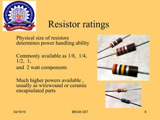


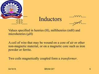


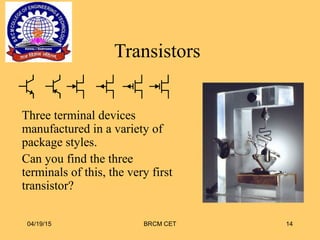

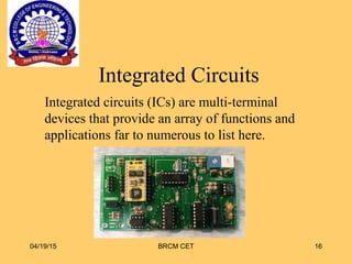


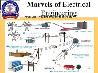


This document provides an overview of electrical and electronics engineering. It defines engineering as improving quality of life by getting things done more effectively and efficiently. It then discusses various passive components like resistors, capacitors, inductors, and diodes. It describes how their values are specified and marked. It also discusses different types of these components. Next, it covers active components like transistors and integrated circuits. It provides examples of different transistor packages and pin identification of integrated circuits. Finally, it discusses the scope of electrical engineering and various career options available for electrical engineers.


![Robotics & Embedded IoT System Design [Day-1]](https://cdn.slidesharecdn.com/ss_thumbnails/roboticsiot-1-170621102837-thumbnail.jpg?width=640&height=640&fit=bounds)


