Downloaded 590 times


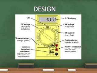
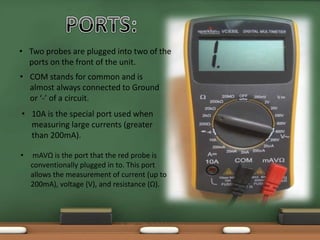
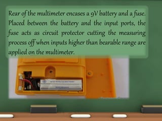
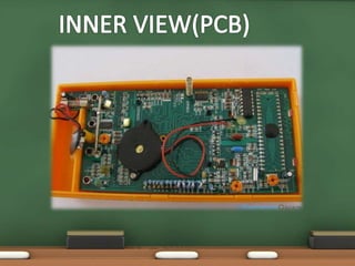
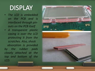


A digital multimeter is a laboratory instrument that can measure AC/DC voltage, AC/DC current, and resistance. It displays measurements digitally for accuracy. A multimeter has a display, selection knob to choose the measurement type, and ports to connect probes that are used to measure circuit characteristics. It runs on a 9V battery and contains a fuse for overcurrent protection. The circuit board hosts components like resistors and integrated circuits to perform measurements shown on the LCD display.


