This document provides an introduction to digital fundamentals and binary systems. It discusses:
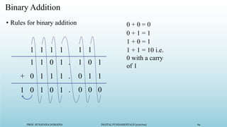
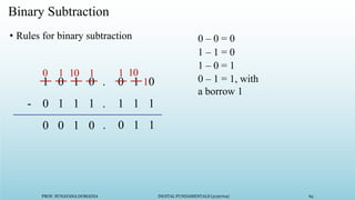
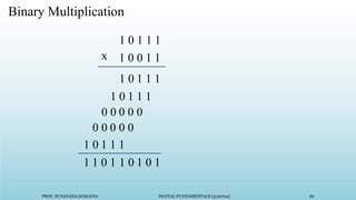
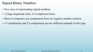
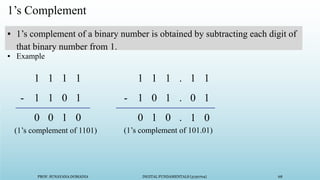
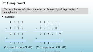
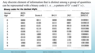
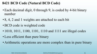
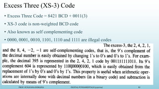
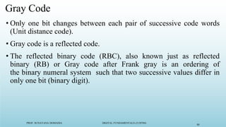
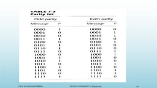
- Binary number systems and logic circuits. Digital systems use binary to represent information as 1s and 0s.
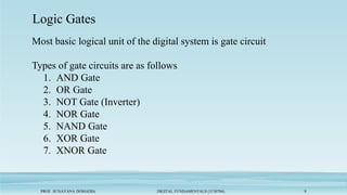
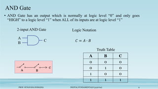
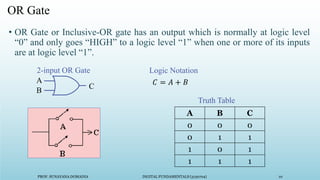
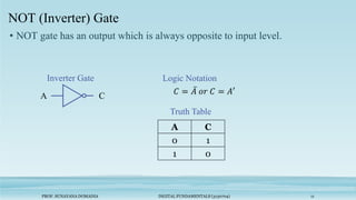
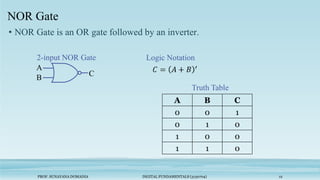
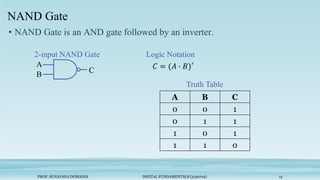
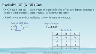
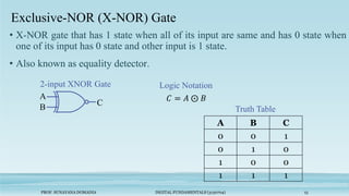
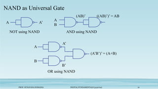
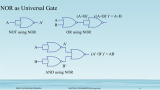
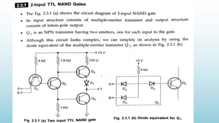
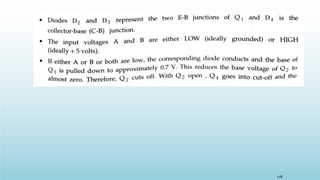
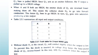
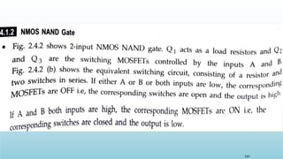
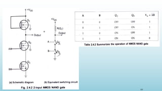
- Common logic gates like AND, OR, NOT and their truth tables. NAND and NOR gates can be used to build other gate types.
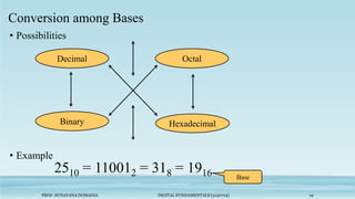
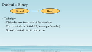
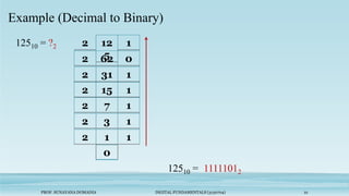
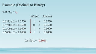
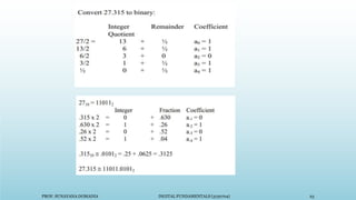
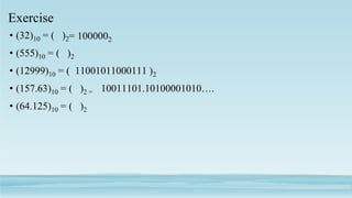
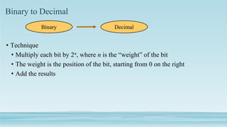
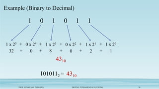
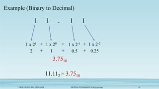
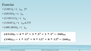
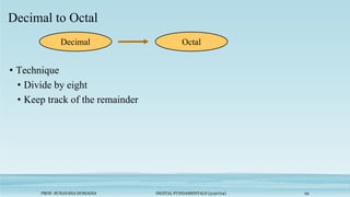
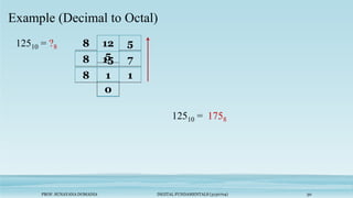
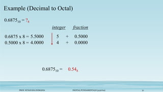
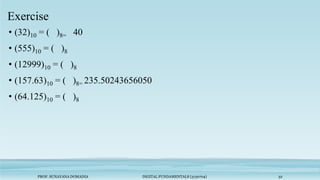
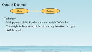
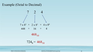
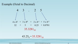
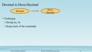
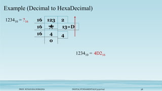
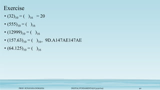
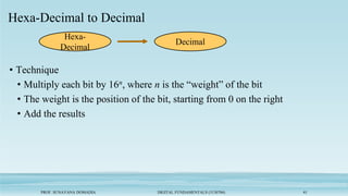
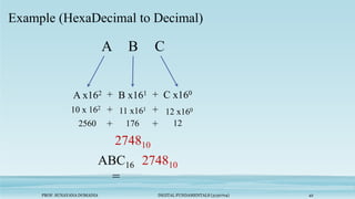
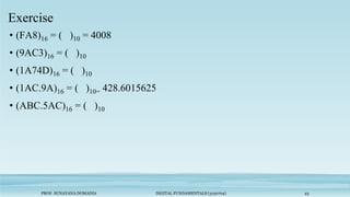
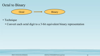
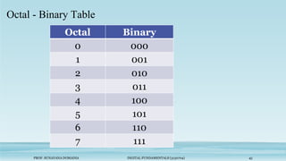
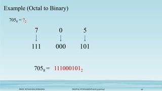
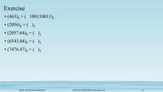
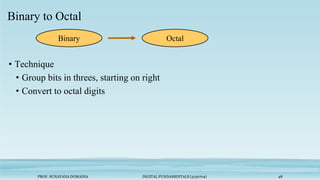
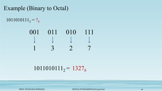
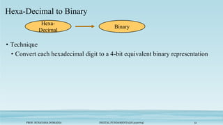
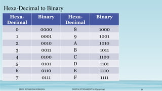
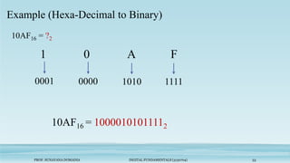
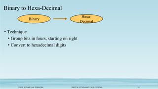
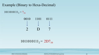
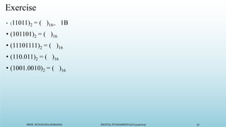
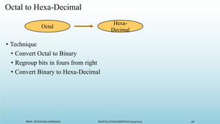
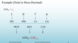
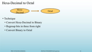
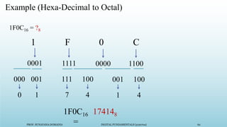
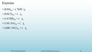
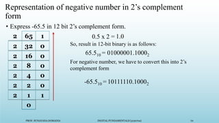
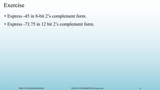
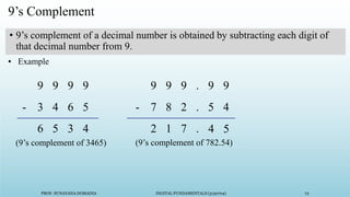
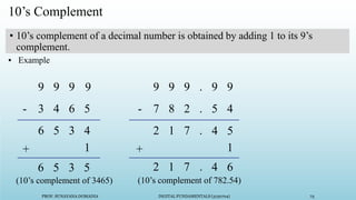
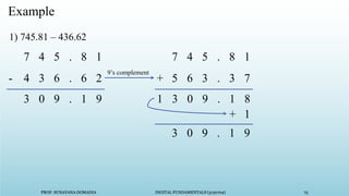
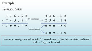
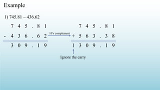
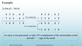
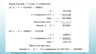
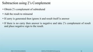
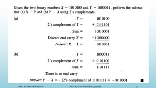
- Converting between number bases like binary, decimal, octal and hexadecimal. Methods for converting include dividing or multiplying by the base and tracking remainders.
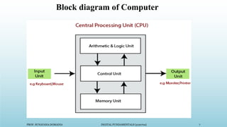
- Applications of digital electronics in computers and other devices that use logic circuits and gates to process digital signals.