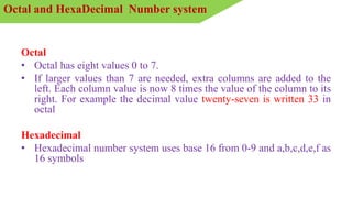
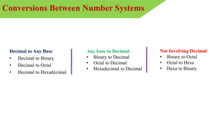
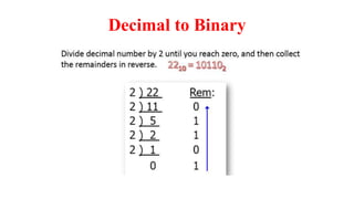
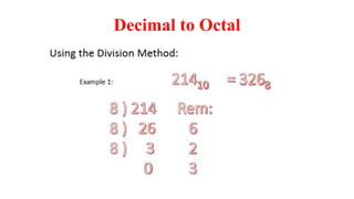
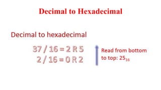
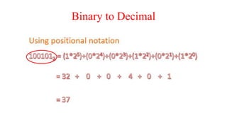
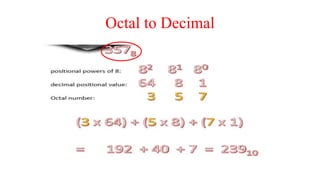
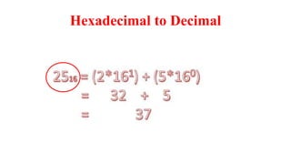
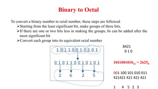
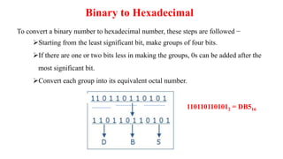
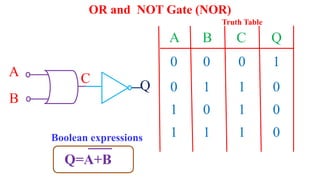
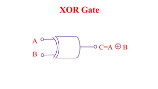
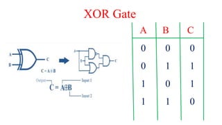
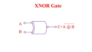
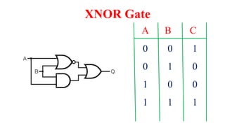
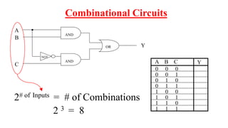
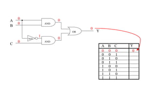
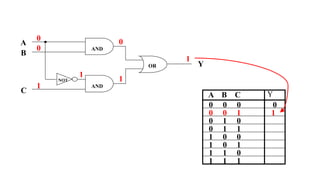
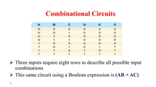
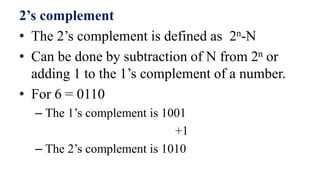
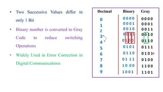
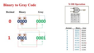
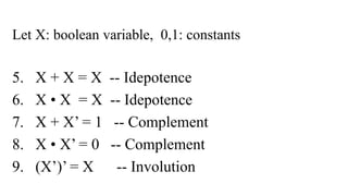
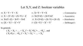
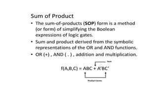
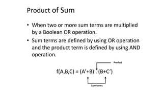
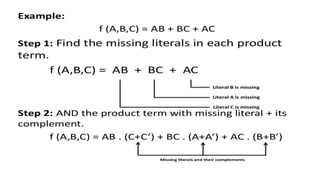
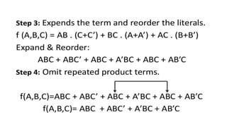
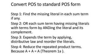
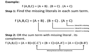
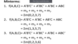
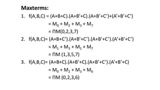
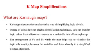
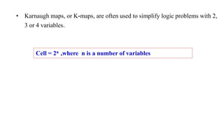
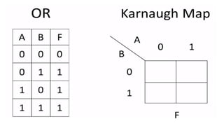
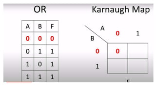
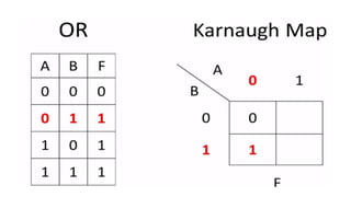
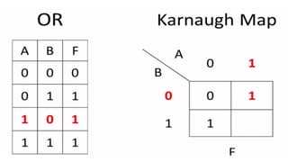
This document outlines the topics covered in the 21EC201 - Digital Principles and System Design course. It includes an introduction to number systems, logic gates, combinational logic circuits, Boolean algebra, truth tables and Karnaugh maps. Specific topics mentioned are binary, decimal, octal and hexadecimal number systems, logic gates like AND, OR, NAND, NOR, XOR and XNOR, arithmetic operations in binary and conversions between different number systems.
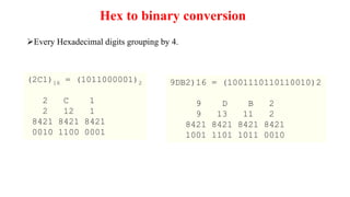
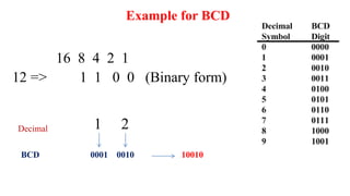
![Octal -> Binary -> Hexadecimal
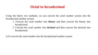
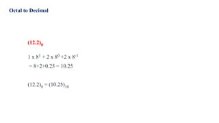
Let's convert (56)8 into hexadecimal
Step 1 : Convert (56)8 into Binary
In order to convert the octal number into binary, we need to express every octal value using 3
binary bits.
Binary equivalent of 5 is (101)2.
Binary equivalent of 6 is (110)2.
= (56)8
= (101)(110)
= (101110)2
Step 2 : Convert (101110)2 into Hexadecimal
In order to convert the binary number into hexadecimal, we need to group every 4 binary bits
and calculate the value[From left to right].
(101110)2 in hexadecimal
= (101110)2
= (10)(1110)
= (2)(14) = = (2E)16](https://image.slidesharecdn.com/21ec201dpsdunit1-230821181338-43254535/85/21EC201-Digital-Principles-and-system-design-pptx-21-320.jpg)


![Lect 1 Number systems and base conversions. [Autosaved].pptx](https://cdn.slidesharecdn.com/ss_thumbnails/lect1numbersystemsandbaseconversions-260111134109-67c2d865-thumbnail.jpg?width=640&height=640&fit=bounds)


