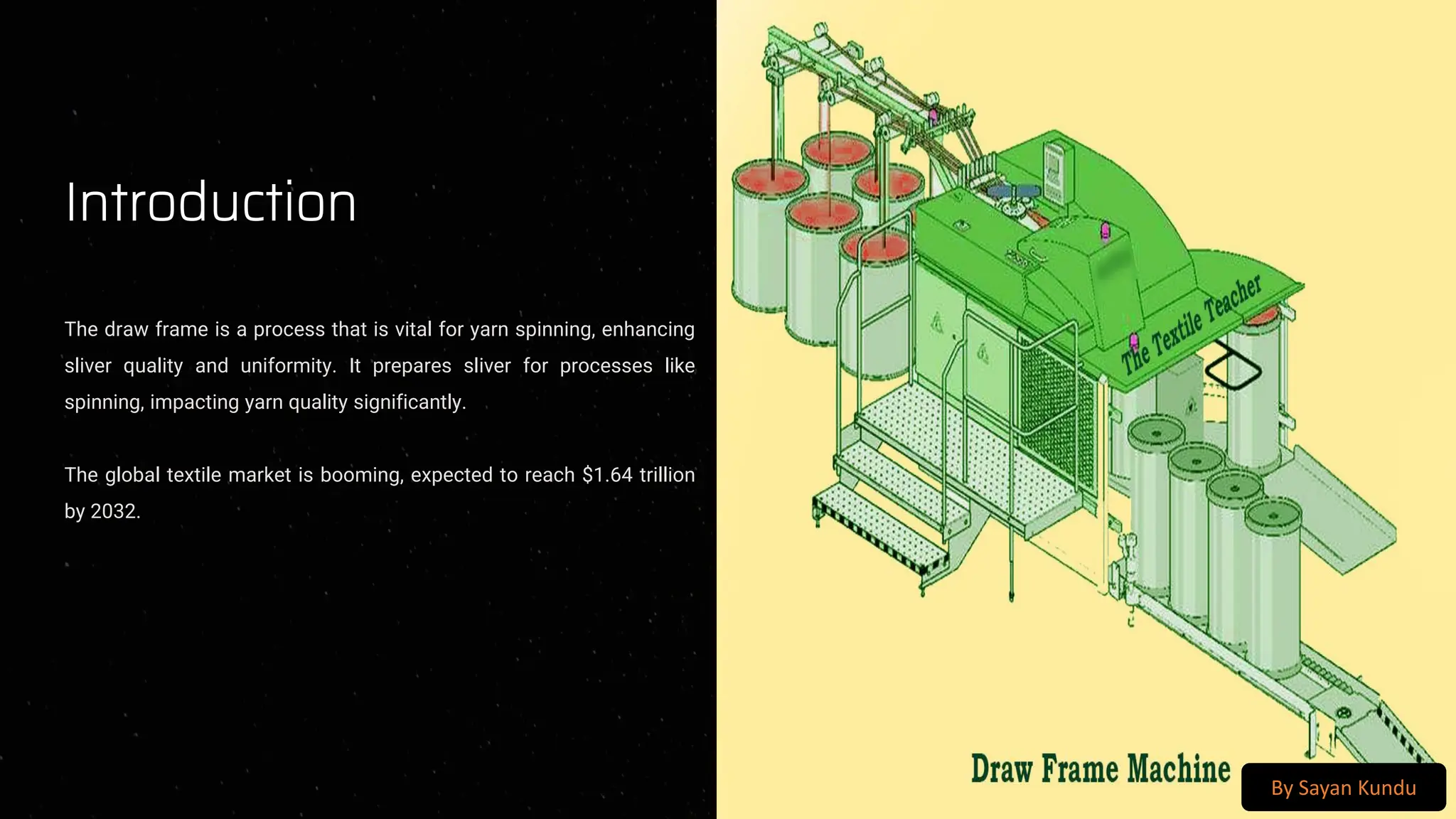
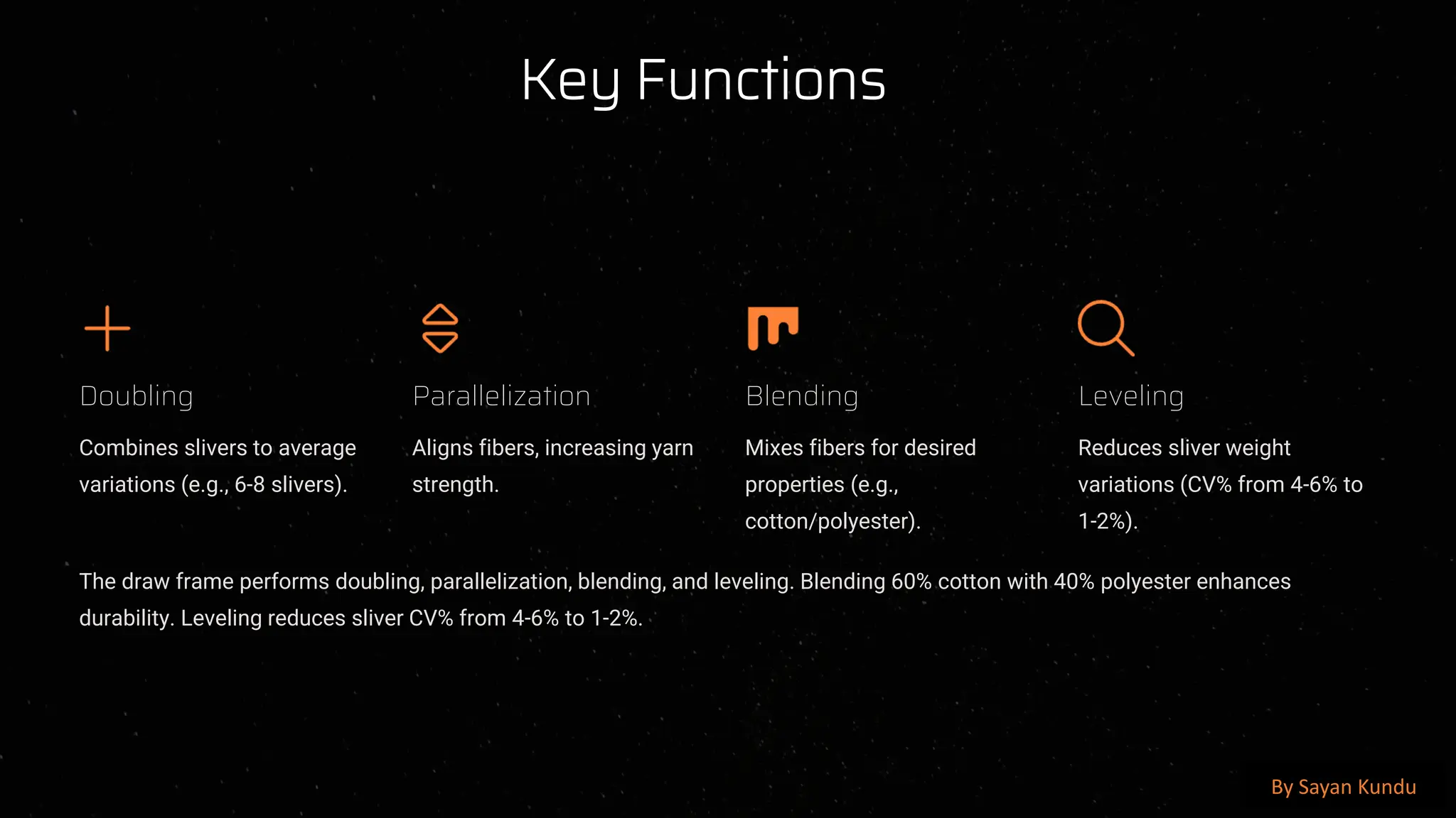
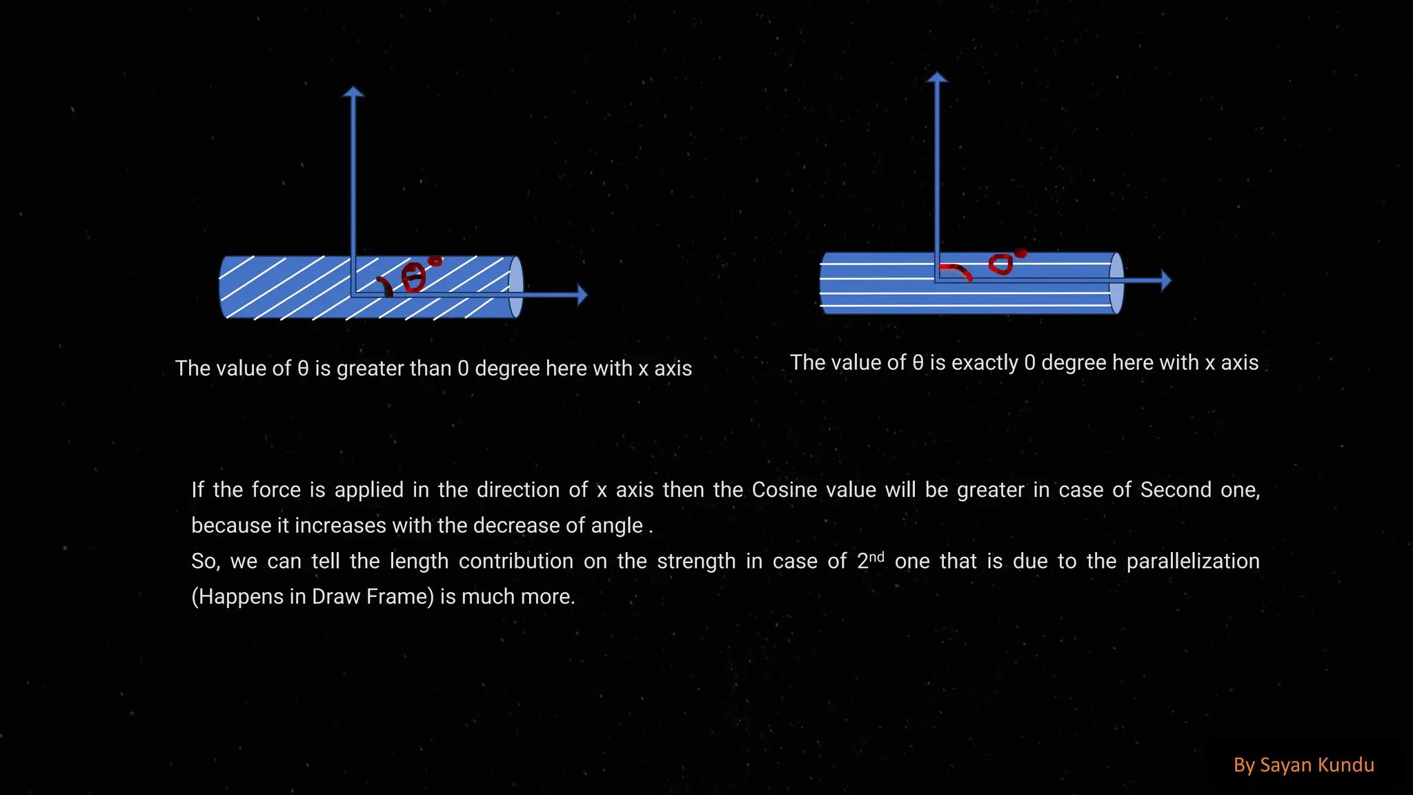
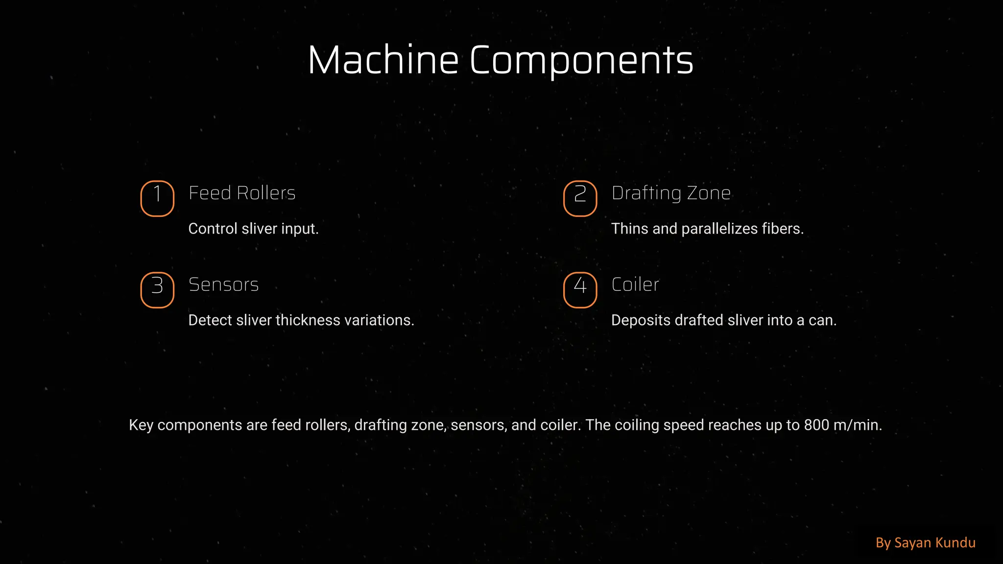
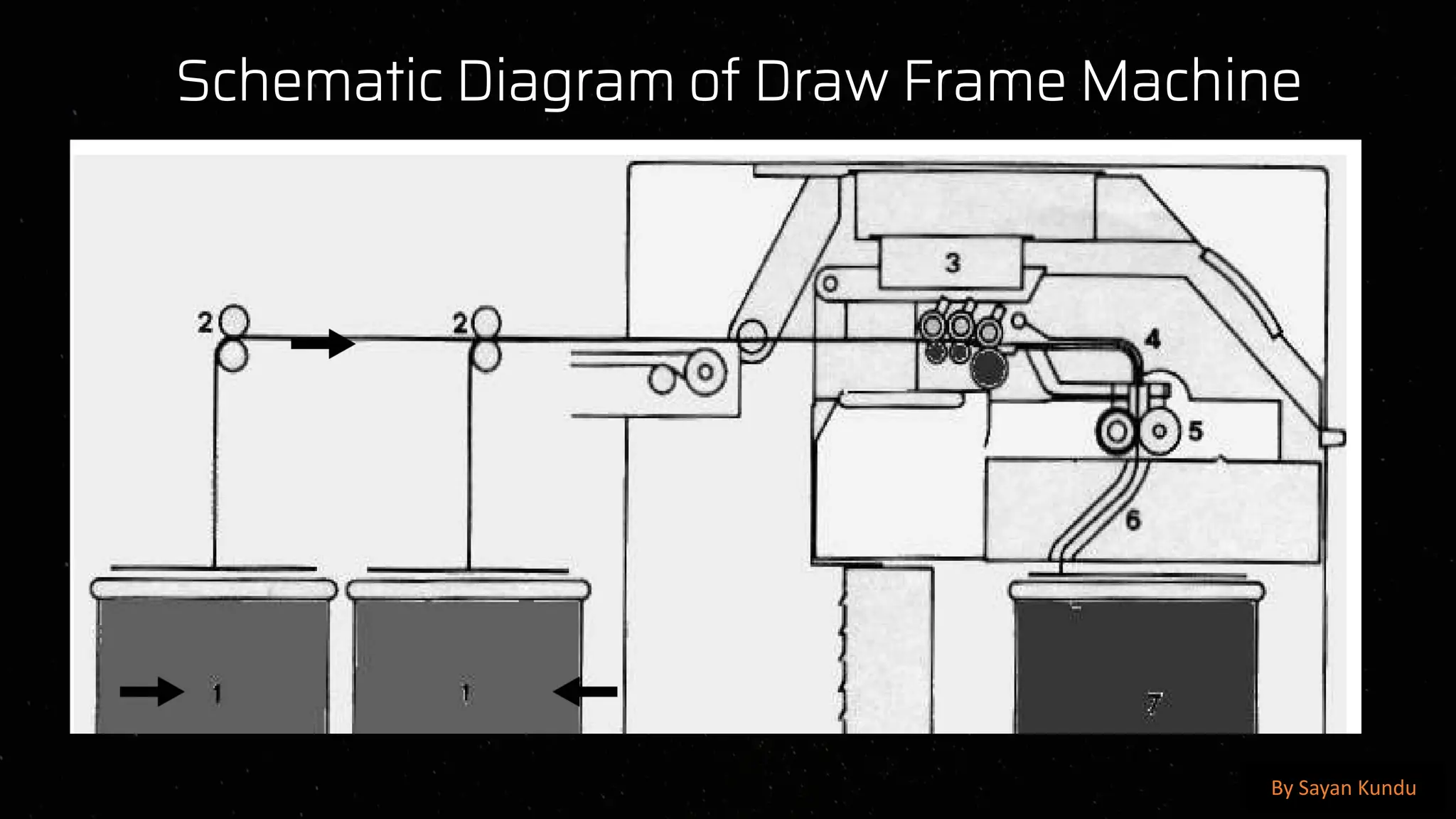
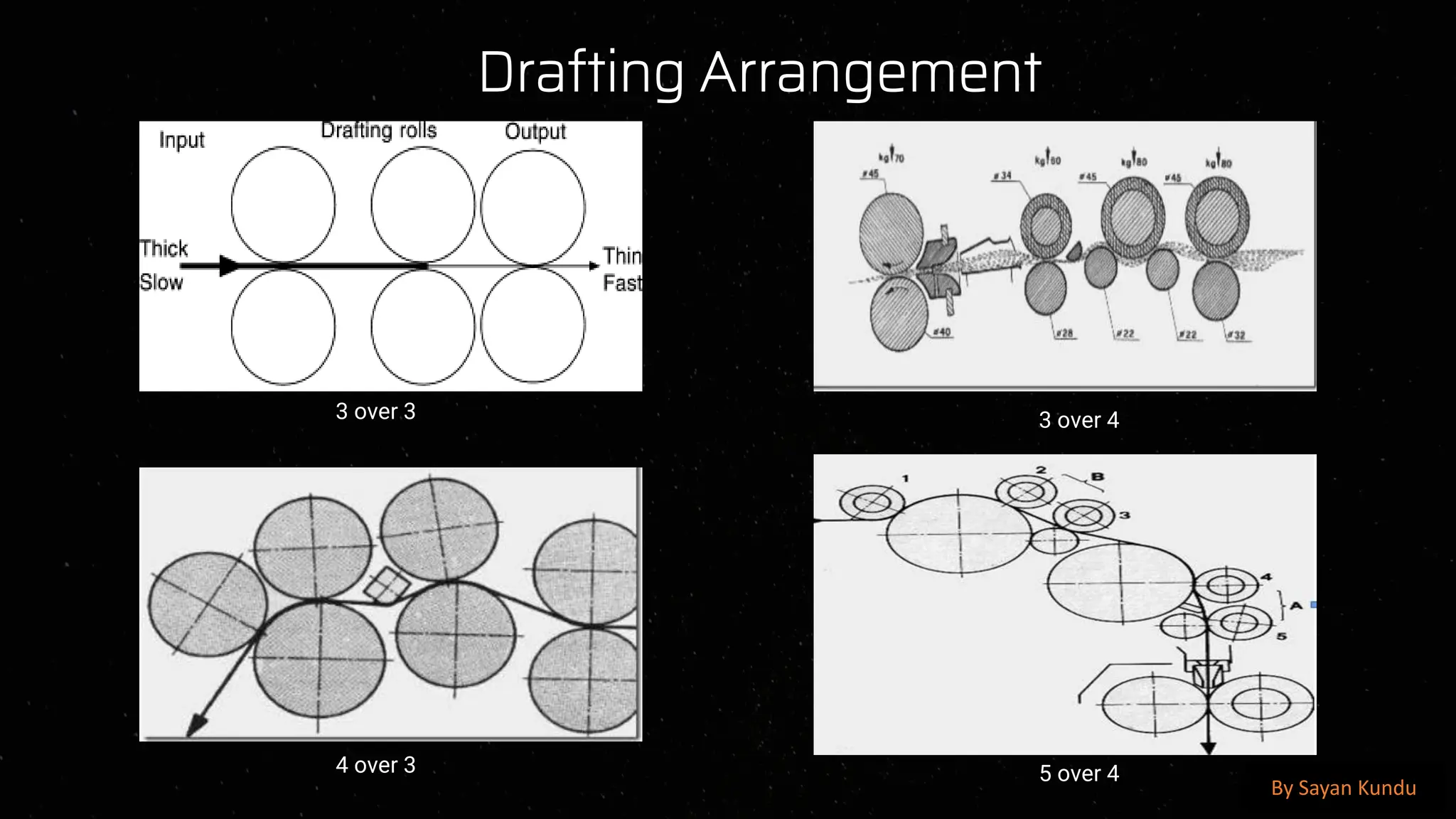
preencoded.png
Draw Frame in
Textile
Manufacturing
By Sayan Kundu
preencoded.png
Introduction
The draw frame is a process that is vital for yarn spinning, enhancing
sliver quality and uniformity. It prepares sliver for processes like
spinning, impacting yarn quality significantly.
The global textile market is booming, expected to reach $1.64 trillion
by 2032.
By Sayan Kundu
preencoded.png
Historical Development
1
Early Draw Frames
Manually operated machines were the
beginning.
2
1730: Lewis Paul
Patented drawing rollers.
3
1857: Heilmann
Rectilinear Comb invented
4
Today
Complex automated systems.
Draw frames evolved from simple manual machines to complex automated systems. Key innovations include drafting systems and
auto-levelers. These milestones shaped modern draw frame technology.
By Sayan Kundu
preencoded.png
❑ Draw Frame contributes less than 5% production cost of the yarn.
❑ It influence on quality, evenness and others
❑ If the draw frame is not properly adjusted there will also be effect on yarn strength and elongation
❑ If any defect arise, that affect on overall process
Currently, The Modern Draw Frame machine has ablity to produce 200kg of sliver per Hour
By Sayan Kundu
preencoded.png
Key Functions
Doubling
Combines slivers to average
variations (e.g., 6-8 slivers).
Parallelization
Aligns fibers, increasing yarn
strength.
Blending
Mixes fibers for desired
properties (e.g.,
cotton/polyester).
Leveling
Reduces sliver weight
variations (CV% from 4-6% to
1-2%).
The draw frame performs doubling, parallelization, blending, and leveling. Blending 60% cotton with 40% polyester enhances
durability. Leveling reduces sliver CV% from 4-6% to 1-2%.
By Sayan Kundu
preencoded.png
The value of θ is greater than 0 degree here with x axis The value of θ is exactly 0 degree here with x axis
If the force is applied in the direction of x axis then the Cosine value will be greater in case of Second one,
because it increases with the decrease of angle .
So, we can tell the length contribution on the strength in case of 2nd one that is due to the parallelization
(Happens in Draw Frame) is much more.
By Sayan Kundu
preencoded.png
Drafting and Auto-Leveling
Drafting Action
Sliver elongation is controlled by rollers
at varying speeds.
Roller Pairs
3-4 pairs increase speed to thin the
sliver.
Auto-Leveling
Continuously monitors and corrects
sliver weight. Feedback system adjusts
roller speeds based on sensor data.
Sliver CV% reduces by up to 50%.
By Sayan Kundu
preencoded.png
Machine Components
1 Feed Rollers
Control sliver input.
2 Drafting Zone
Thins and parallelizes fibers.
3 Sensors
Detect sliver thickness variations.
4 Coiler
Deposits drafted sliver into a can.
Key components are feed rollers, drafting zone, sensors, and coiler. The coiling speed reaches up to 800 m/min.
By Sayan Kundu
preencoded.png
Schematic Diagram of Draw Frame Machine
By Sayan Kundu
preencoded.png
Process Overview
Fiber Straightening
Fibers align upon entry.
Drafting
Sliver thins gradually.
Sliver Uniformity
Consistent weight and distribution.
The process involves fiber straightening, drafting, and achieving sliver uniformity. Typical draft ratios range from 6 to 12, with a
target sliver weight deviation of ± 1-2%.
By Sayan Kundu
preencoded.png
Drafting Arrangement
3 over 3
5 over 4
4 over 3
3 over 4
By Sayan Kundu
preencoded.png
Type of Drafting Rollers
Top Drafting Rollers
➢ Coated with material made by rubber
➢ Gives greater gripping during the time of material passing
➢ Prevent from slippage
By Sayan Kundu
preencoded.png
Bottom Drafting Rollers
Design is made to prevent from slippage
In case of simple 3 over 3 Drafting arrangements generally,
Axial Flutes presents in Middle Drafting roller
Helical Flutes presents in Back Drafting roller
Knurl Flutes presents in Front Drafting roller
Axial Flutes Helical Flutes Knurled Flutes
By Sayan Kundu
preencoded.png
Types of Draw Frames
Breaker Draw Frame
First stage, handles coarser slivers, and
reduces fiber mass.
Finisher Draw Frame
Second stage, processes finer slivers for
improved uniformity, preparing for spinning.
By Sayan Kundu
preencoded.png
Advances in Technology
Automated Sliver Handling
Robotic systems for can changes.
Real-Time Monitoring
Data analytics for optimization.
Servo-Driven Systems
Precise roller control. Improving U% by 10-15%
Integrated Control
Automatic defect detection. Industry 4.0 Integration
Modern draw frames feature automated handling, real-time monitoring, and servo-driven systems. These improve efficiency and
product quality. Industry 4.0 enables remote control.
By Sayan Kundu
preencoded.png
Conclusion
The draw frame is critical for high-quality, uniform yarn. Benefits include improved
strength, evenness, and dyeability. Technology advancements drive efficiency. The
global textile machinery market is projected to reach $35 billion by 2027.
By Sayan Kundu

Details about Draw-Frame-in-Textile-Manufacturing.pdf

  • 1.
  • 2.
    preencoded.png Introduction The draw frameis a process that is vital for yarn spinning, enhancing sliver quality and uniformity. It prepares sliver for processes like spinning, impacting yarn quality significantly. The global textile market is booming, expected to reach $1.64 trillion by 2032. By Sayan Kundu
  • 3.
    preencoded.png Historical Development 1 Early DrawFrames Manually operated machines were the beginning. 2 1730: Lewis Paul Patented drawing rollers. 3 1857: Heilmann Rectilinear Comb invented 4 Today Complex automated systems. Draw frames evolved from simple manual machines to complex automated systems. Key innovations include drafting systems and auto-levelers. These milestones shaped modern draw frame technology. By Sayan Kundu
  • 4.
    preencoded.png ❑ Draw Framecontributes less than 5% production cost of the yarn. ❑ It influence on quality, evenness and others ❑ If the draw frame is not properly adjusted there will also be effect on yarn strength and elongation ❑ If any defect arise, that affect on overall process Currently, The Modern Draw Frame machine has ablity to produce 200kg of sliver per Hour By Sayan Kundu
  • 5.
    preencoded.png Key Functions Doubling Combines sliversto average variations (e.g., 6-8 slivers). Parallelization Aligns fibers, increasing yarn strength. Blending Mixes fibers for desired properties (e.g., cotton/polyester). Leveling Reduces sliver weight variations (CV% from 4-6% to 1-2%). The draw frame performs doubling, parallelization, blending, and leveling. Blending 60% cotton with 40% polyester enhances durability. Leveling reduces sliver CV% from 4-6% to 1-2%. By Sayan Kundu
  • 6.
    preencoded.png The value ofθ is greater than 0 degree here with x axis The value of θ is exactly 0 degree here with x axis If the force is applied in the direction of x axis then the Cosine value will be greater in case of Second one, because it increases with the decrease of angle . So, we can tell the length contribution on the strength in case of 2nd one that is due to the parallelization (Happens in Draw Frame) is much more. By Sayan Kundu
  • 7.
    preencoded.png Drafting and Auto-Leveling DraftingAction Sliver elongation is controlled by rollers at varying speeds. Roller Pairs 3-4 pairs increase speed to thin the sliver. Auto-Leveling Continuously monitors and corrects sliver weight. Feedback system adjusts roller speeds based on sensor data. Sliver CV% reduces by up to 50%. By Sayan Kundu
  • 8.
    preencoded.png Machine Components 1 FeedRollers Control sliver input. 2 Drafting Zone Thins and parallelizes fibers. 3 Sensors Detect sliver thickness variations. 4 Coiler Deposits drafted sliver into a can. Key components are feed rollers, drafting zone, sensors, and coiler. The coiling speed reaches up to 800 m/min. By Sayan Kundu
  • 9.
    preencoded.png Schematic Diagram ofDraw Frame Machine By Sayan Kundu
  • 10.
    preencoded.png Process Overview Fiber Straightening Fibersalign upon entry. Drafting Sliver thins gradually. Sliver Uniformity Consistent weight and distribution. The process involves fiber straightening, drafting, and achieving sliver uniformity. Typical draft ratios range from 6 to 12, with a target sliver weight deviation of ± 1-2%. By Sayan Kundu
  • 11.
    preencoded.png Drafting Arrangement 3 over3 5 over 4 4 over 3 3 over 4 By Sayan Kundu
  • 12.
    preencoded.png Type of DraftingRollers Top Drafting Rollers ➢ Coated with material made by rubber ➢ Gives greater gripping during the time of material passing ➢ Prevent from slippage By Sayan Kundu
  • 13.
    preencoded.png Bottom Drafting Rollers Designis made to prevent from slippage In case of simple 3 over 3 Drafting arrangements generally, Axial Flutes presents in Middle Drafting roller Helical Flutes presents in Back Drafting roller Knurl Flutes presents in Front Drafting roller Axial Flutes Helical Flutes Knurled Flutes By Sayan Kundu
  • 14.
    preencoded.png Types of DrawFrames Breaker Draw Frame First stage, handles coarser slivers, and reduces fiber mass. Finisher Draw Frame Second stage, processes finer slivers for improved uniformity, preparing for spinning. By Sayan Kundu
  • 15.
    preencoded.png Advances in Technology AutomatedSliver Handling Robotic systems for can changes. Real-Time Monitoring Data analytics for optimization. Servo-Driven Systems Precise roller control. Improving U% by 10-15% Integrated Control Automatic defect detection. Industry 4.0 Integration Modern draw frames feature automated handling, real-time monitoring, and servo-driven systems. These improve efficiency and product quality. Industry 4.0 enables remote control. By Sayan Kundu
  • 16.
    preencoded.png Conclusion The draw frameis critical for high-quality, uniform yarn. Benefits include improved strength, evenness, and dyeability. Technology advancements drive efficiency. The global textile machinery market is projected to reach $35 billion by 2027. By Sayan Kundu