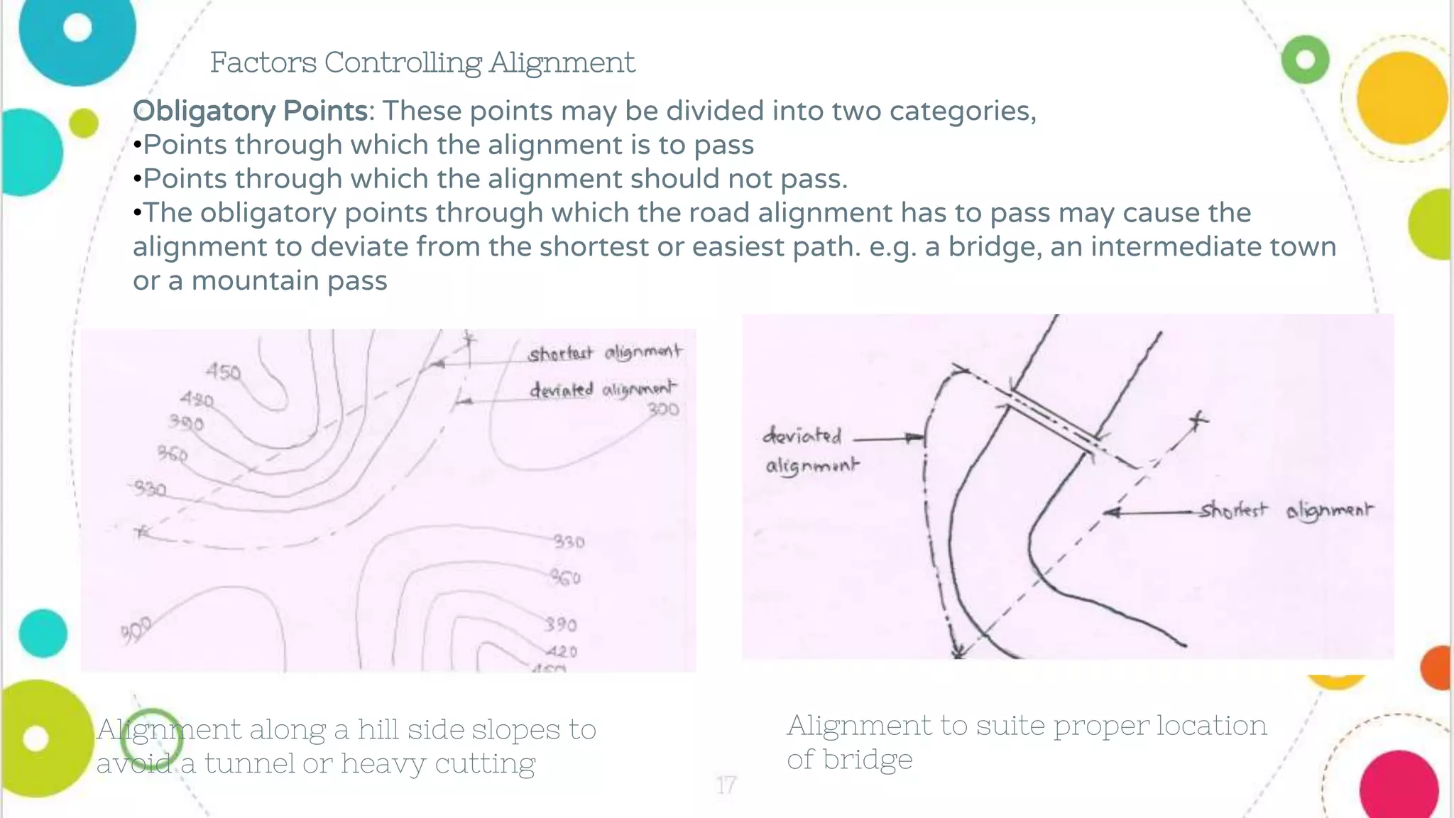
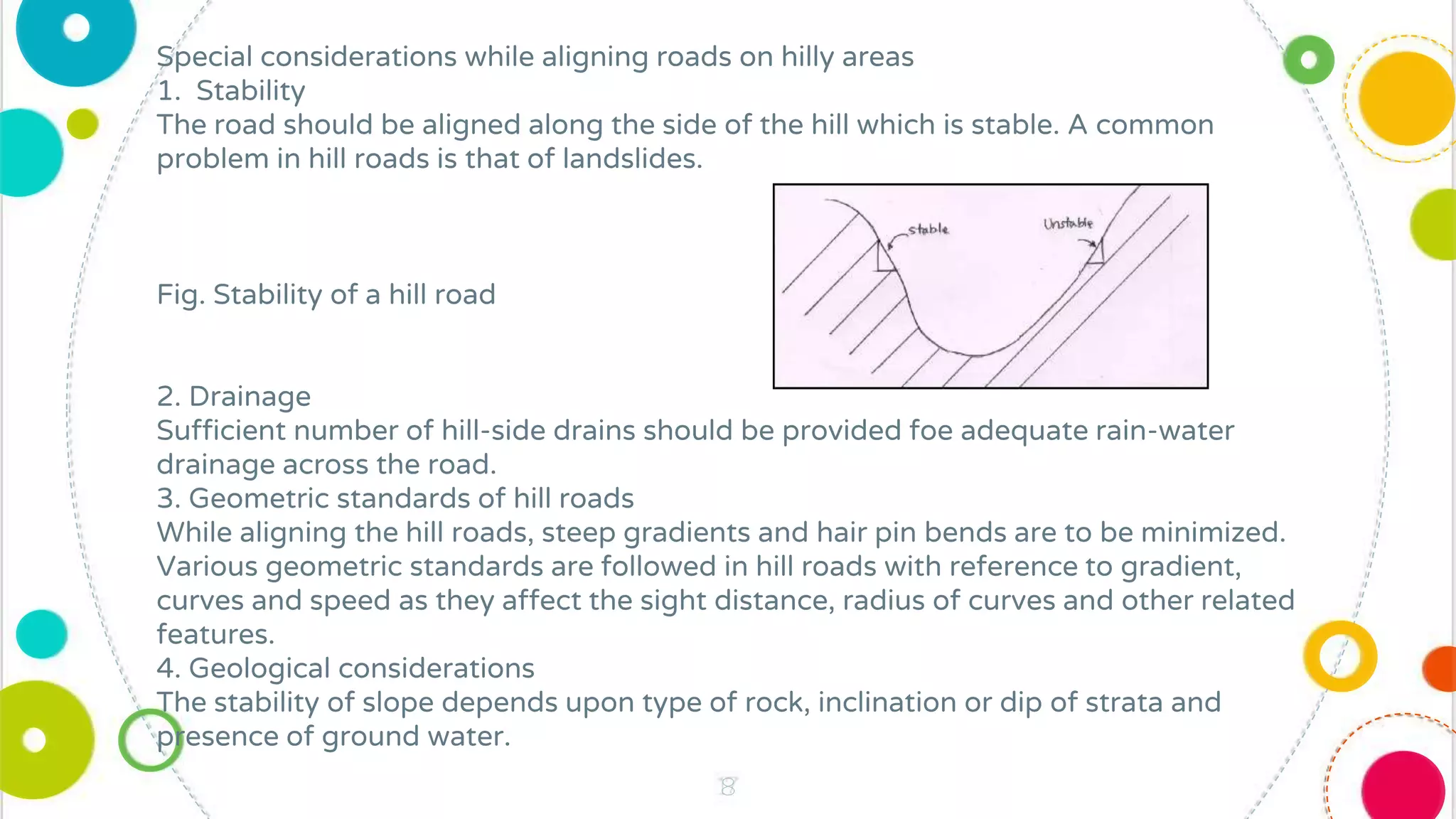
Highway
Geometric
Design
by,
Ms.Priya Sarita Mane
2
Content
• Design of horizontal alignment: horizontal curves, design of super
elevation and its provision, radius at horizontal curves, widening of
pavements at horizontal curves, analysis of transition curves.
• Design of vertical alignment: different types of gradients, grade
compensation on curves, analysis of vertical curves, summit curves,
valley curves.
• Intersection: at grade and grade separated intersections, speed
change lanes, Canalization, Design of rotary intersection and mini
roundabout.
3
•Highway geometric design mainly deals with the dimensions and layout of
horizontal and vertical alignments such as cross-sectional components, horizontal
curves and gradients, vertical curves and gradients, various sight distances and
components of intersections. These design features are very important from the view
point of safety and economy of the new proposed roads as well as the existing roads
needing improvements.
•Highway geometric design depends on the topography or the terrain through
which the highway is aligned. The other factors influencing the geometric design are
traffic characteristics, road user characteristics, traffic characteristics, design
speed, economy, etc.
•Definition: The position or the layout of the centre-line of the highway on the
ground is called the alignment.
•Horizontal Alignment: The horizontal alignment includes the straight path,
the horizontal deviations and curves.
•Vertical Alignment: The vertical alignment includes the vertical curves and
changes in gradient.
4
The basic requirements of an ideal alignment between two terminal stations are
that it should be short, easy, safe and economical
•Short: The alignment between two terminal stations should be as short as
possible. A straight alignment would be the shortest but some practical
considerations may cause deviations from the shortest path.
•Easy: The alignment should be such that it is easy to construct and maintain the
road. The alignment should be easy for the operation of vehicles with easy
gradient and curves.
•Safe: The alignment should be safe enough for construction and maintenance
from the view point of stability of natural slopes, embankments, etc. The
alignment should be safe for the traffic operation with safe geometric features.
•Economical: The alignment would be economical if the total cost including initial
cost, maintenance cost and vehicle operation cost is lowest.
Alignment to suite proper location
of bridge
Alignment along a hill side slopes to
avoid a tunnel or heavy cutting
Obligatory Points: These points may be divided into two categories,
•Points through which the alignment is to pass
•Points through which the alignment should not pass.
•The obligatory points through which the road alignment has to pass may cause the
alignment to deviate from the shortest or easiest path. e.g. a bridge, an intermediate town
or a mountain pass
Factors Controlling Alignment
Connecting intermediate town C
Obligatory points through which the road alignment should not pass also
may cause the deviation of the proposed shortest alignment.
e.g. religious places, waterlogged and marshy areas, lake, pond, etc.
Geometric design features
Geometric design features such as radius of curve, gradient, sight distance, super
elevation, etc. also govern the alignment.
◎ Traffic requirements
The alignment should suit the traffic requirements both, present and future.
◎ Economy
The alignment should be economical. The initial cost of construction can be decreased if
high embankments and deep cuttings are avoided. The alignment should be chosen in
order to balance the cutting and filling.
Other considerations
◎ Various other factors which may govern the alignment are drainage considerations,
hydrological factors, environmental aspects, political considerations, strategic
factors and monotony.
◎ Very long stretch of absolute straight road may be monotonous for driving. Hence,
after a few kilometers of straight road, a slight bend should be given to break the
monotony and keep the driver alert.
8
Special considerations while aligning roads on hilly areas
1. Stability
The road should be aligned along the side of the hill which is stable. A common
problem in hill roads is that of landslides.
Fig. Stability of a hill road
2. Drainage
Sufficient number of hill-side drains should be provided foe adequate rain-water
drainage across the road.
3. Geometric standards of hill roads
While aligning the hill roads, steep gradients and hair pin bends are to be minimized.
Various geometric standards are followed in hill roads with reference to gradient,
curves and speed as they affect the sight distance, radius of curves and other related
features.
4. Geological considerations
The stability of slope depends upon type of rock, inclination or dip of strata and
presence of ground water.
9
Curve:
•Road Curves play a vital role in the geometric design of road and railway alignments. Hence, it must
be properly studied and designed so as to provide safety, comfort and convenience at the time of driving
the vehicles or train on road curves.
•The geometrical arc provided at change in alignment or gradient of road are known as curves.
Necessity of Road Curves :
•Straight route of road is always desirable, since provides economy in the cost of construction,
transportation and finally maintenance.
•But when there is a change in alignment or gradient of road, then it becomes a need to provide curves
under following circumstances​
1.Excessive cutting or filling can be prevented by providing the change in alignment by road curve.
2.The obstruction like natural or artificial which comes in the way of straight alignment can be made
easier by providing the by-pass with the help of curves.
3.In the straight route, gradients are made more comfortable and easy by providing diversions with the
help of road curves.
4.In a straight route, if costly land comes in the way, then can be avoided by providing diversions with
the help of curves.
5.Track or road is made stable and safe side of the hill by changing the alignment.
10
Functions of Curves on Road Alignment
1. Following are the various types of functions of the road curves which takes place in the alignment
of road or railway track.
2. Gradual change in direction or orientation in the alignment can be made by providing the curves. .
Road curves are provided so as to get comfort to the passengers.
4. Gradual change in the direction or orientation in the alignment can be made by providing the curves.
5. Curves are provided so as to get easy turning in case of road and track.
Types of
Curves
Horizontal
Curve
Simple Compound Reverse Transition
Vertical
curve
Summit Valley
11
•Horizontal Curves
•The curve provided in the horizontal plane of ground or earth is
called a horizontal curve.
•It connects two straight lines which are in the same level but
having different or the same directions.
•There are different types of horizontal curves, each of them is
explained below.
1. Simple circular curve
•It is a curve consisting of a single arc with a constant radius
connecting the two tangents.
•It is a type of horizontal curve used most in common.
•A simple arc provided in the road to impose a curve between the
two straight lines is the simple circular curve.
•The smaller is the degree of curve, the flatter is the curve and
vice versa.
•The sharpness of a simple curve is also determined by radius R.
•Large radius are flat whereas small radius are sharp.
•A simple curve is normally represented by the length
of its radius or by the degree of curve​
12
2. Compound curve
•A curve of having the series of two and more
simple curves of different radius curving in the
same direction is called as compound curves.
•In compound curves, the two adjacent curves
will have a common tangent ‘BC’ as shown in
above figure.
•The centers of two adjacent curve lie on the
same side of the curve as shown in above figure.
•To avoid the cutting through hard rocks, heavy
cutting or filling in the alignment of road or
track, compound curves are provided.
3. Reverse Curve :
•The curve which consists of two simple curve
having equal or different radii turning in
opposite direction is called as reverse
curve. The two centers of curves are on
opposite sides of a common tangent ‘BD’.
•Reverse curves are necessary on hill roads
where frequently changes in the direction of
travel is required. Reverse curves are also
necessary for cross-overs in station yards and in
the alignment of the railway tracks in hilly
areas.
13
4. Transition Curve :
•The transition curve is defined as the curve in which radius varies gradually from
infinity to a finite value equal to that of the circular curve to be connected and vice
versa is termed as transition curve.
14
•Design Of Horizontal Alignment
•Often changes in the direction are necessitated in highway alignment due to various reasons such
as topographic considerations, obligatory points.
•The geometric design elements pertaining to horizontal alignment of highway should consider
safe and comfortable movement of vehicles at the designated design speed of the highway.
•It is therefore necessary to avoid sudden changes in direction with sharp curves or reverse curves
which could not be safely and conveniently negotiated by the vehicles at design speed.
•Improper design of horizontal alignment of roads would necessitate speed changes resulting m
higher accident rate and increase in vehicle operation cost.
•Various design elements to be considered in the horizontal alignment are design speed radius of
circular curve, type and length of transition curves, super elevation, widening of pavement on
curves and required set-back distance for fulfilling sight distance requirements.
•Design Speed
•The design speed is the main factor on which geometric design elements depends. In other words,
the geometric details of a highway mainly depend on the design speed.
•All the important geometric elements such as sight distances, radius of horizontal curve, length of
horizontal transition curve, rate of super elevation, extra widening of pavement at horizontal curve,
length of summit and valley curves are dependent on the design speed.
•The design speed of roads depends upon
1) Class of the Road
2) Terrain
15
•The speed standards of a particular class of road thus depends on the classification of terrain
through which it passes. The terrains have been classified as plain, mountainous and steep,
depending on the cross slope of the country as given in table below​
•Two values of design speeds are considered at the design stage of highway geometries
namely,
1.Ruling design speed
2) Minimum design speed
•As a general rule, attempt should be made to design all the geometric element of the highway
for the 'ruling design speed'.
•This is because ruling design speeds are guiding criteria for the geometric design.
•However, 'minimum design speed’ may be accepted where site conditions or economic
considerations warrant.
•The ruling design speeds suggested for the National and State Highways in India passing
through plain terrain is 100 kmph and through rolling terrain is 80kmph and minimum design
speed values standardized by the IRC for of roads on different terrains in rural (non-urban)
areas are given in Table below​
16
•The recommended design speeds for different classes of urban roads
1.Arterial Roads: 80 Kmph
2.Sub-Arterial Roads: 60 Kmph
3.Collector Streets: 50 Kmph
4.Local Streets: 30 Kmph
 Horizontal Curves
• A horizontal highway curve is a curve in plan to provide change in direction to the centre line of a road.
• A simple circular curve may be designated by either the radius, R of the curve in meters or the degree, D of the curve.
• The degree of the curve (D°) is the central angle subtended by an arc of length 30 m and is given by the relation,
RD𝜋/180 = 30.
• Therefore, the relation between the radius and degree of the circular curve is given by,
R = 1720 / D
• When a vehicle traverses a horizontal curve, the centrifugal force acts horizontally outwards through the centre of
gravity of the vehicle.
• The centrifugal force developed depends on the radius of the horizontal curve and the speed of the vehicle negotiating
the curve.
• This centrifugal force is counteracted by the transverse frictional resistance developed between the tyres and the
pavement which enables the vehicle to change the direction along the curve and to maintain the stability of the
vehicle.
• Centrifugal force P is given by the equation:
Where
P = centrifugal force, kg
W = weight of the vehicle, kg
R = radius of the circular curve, m
v = speed of vehicle, m/sec
g = acceleration due to gravity = 9.8 m/sec
• The ratio of the centrifugal force to the weight of the vehicle, P/W is known as the 'centrifugal ratio' or the 'impact
factor'. Therefore, centrifugal ratio
• The centrifugal force acting on a vehicle negotiating a horizontal curve has the following two effects:
1) Tendency to overturn the vehicle outwards about the outer wheels
2) Tendency to skid the vehicle laterally, outwards
 Overturning Effect
• The overturning moment due to centrifugal force, P = P x h
• This is resisted by the restoring moment due to weight of the vehicle W and is equal to (Wb/2)
• The equilibrium condition for overturning will occur when
• overturning will occur
• And for safety
 Transverse Skidding Effect
• The centrifugal force developed has the tendency to push the vehicle outwards in the transverse direction.
• The equilibrium condition for the transverse skid resistance developed is given by
F = FA + FB
= f (RA + RB)
= f W
• Where f = coefficient of friction between the tyre and the pavement surface in the transverse direction
• RA, RB = Normal Reactions at the wheels A and B
• W = weight of the vehicle
• When the centrifugal skidding takes place
• For safety
• Thus, to avoid both overturning and lateral skidding on a horizontal curve, the
Superelevation
• In order to counteract the effect of centrifugal force and to reduce the tendency of the vehicle to
overturn or skid, the outer edge of the pavement is raised with respect to the inner edge, thus providing
a transverse slope throughout the length of the horizontal curve. This transverse inclination to the
pavement surface is known as superelevation or banking or cant.
• The superelevation ‘e’ is expressed as the ratio of the height of outer edge and the horizontal width.
• 𝑒 =
𝐸
𝐵
• Superelevation ‘e’ is expressed as, 𝑒 + 𝑓 =
𝑉2
127 𝑅
• Where,
e = rate of superelevation in m/m
f = coefficient of friction between pavement and tyres = 0.15
V = speed in kmph
R = radius of horizontal curve, m.
IRC Recommendation:
• Superelevation should be limited to the following values,
• In plain and rolling terrain: 7% (1 in 15)
• In hilly terrain: 10% (1 in 10)
• On urban roads: 4% (1 in 25)
Ex. 1 Calculate the superelevation for a national highway in plain terrain situated on a curve of
280 m radius and design speed of 75 kmph by considering the friction with f = 0.12.
Solution:
1. Superelevation is given by, 𝑒 + 𝑓 =
𝑉2
127 𝑅
• Given:
Coefficient of friction, f = 0.12
Design speed, V = 75 kmph
Radius of curve, R = 280 m
𝑒 + 0.12 =
75 2
127 280
e = 0.04 = 4% i.e. 1 in 25
Ex. 2 Calculate the superelevation required on a road curve of radius 240 m for a permissible
speed of 96 kmph. The coefficient of friction is 0.12. (SU Dec. 2014)
Solution:
• Superelevation is given by, 𝑒 + 𝑓 =
𝑉2
127 𝑅
Given:
• Coefficient of friction, f = 0.12
Design speed, V = 96 kmph
• Radius of curve, R = 240 m
• Width of road, B = 15 m
𝑒 + 0.12 =
96 2
127 240
e = 0.18 = 18%
• Since the maximum limit of superelevation is 7%, the design superelevation will be 7% or 1 in 15
Ex 3: Calculate the maximum allowable speed on a horizontal curve of radius 350 m if the
maximum allowable value of lateral coefficient of friction is 0.15 and the rate of superelevation is
0.07.
• Solution:
• Superelevation is given by, 𝑒 + 𝑓 =
𝑉2
127 𝑅
• Given:
• Rate of superelevation, e = 0.07
• Coefficient of friction, f = 0.15
• Design speed, V =?
• Radius of curve, R = 350 m
0.07 + 0.15 =
𝑉 2
127 350
Design of Superelevation (IRC Method)
Step 1: The superelevation for 75% of design speed is calculated neglecting the friction.
𝒆 =
𝟎.𝟕𝟓 𝑽 𝟐
𝟏𝟐𝟕 𝑹
Step 2: If the calculated value is less than 0.07, the value so obtained is provided.
• If the calculated value exceeds 0.07, then provide the maximum superelevation equal to 0.07.
Step 3: Check the coefficient of friction developed for maximum value of e = 0.07 at the full value of design speed.
𝒇 =
𝑽𝟐
𝟏𝟐𝟕 𝑹
− 𝟎. 𝟎𝟕
• If the value of f is less than 0.15, the superelevation of 0.07 is safe for the design speed. If not, calculate the
restricted speed as given in Step 4.
Step 4: 𝑆𝑎𝑓𝑒 𝑎𝑙𝑙𝑜𝑤𝑎𝑏𝑙𝑒 𝑠𝑝𝑒𝑒𝑑 𝑉𝑎 = 27.94 𝑅
• If the calculated allowable speed is more than the design speed, then provide a superelevation of 0.07.
• If the allowable speed is less than the design speed, the speed limit is limited to the allowable speed Va kmph.
Ex.1: Design the rate of superelevation for a horizontal highway curve of radius 500 m and speed 100 kmph.
• Solution:
Step 1: The superelevation for 75% of design speed is calculated neglecting the friction.
𝑒 =
0.75 𝑉 2
127 𝑅
=
0.75 𝑥 100 2
127 𝑥 500
= 0.089
• Step 2: As the value of e is greater than 0.07, the actual superelevation to be provided is restricted to 0.07.
• Step 3: Check the coefficient of lateral friction for full speed
𝑓 =
𝑉2
127 𝑅
− 0.07 =
100 2
127 𝑥 500
− 0.07 = 0.087
• As the value is less than 0.15, the design is safe with superelevation of 0.07.
 Ex.5: Design the superelevation as per IRC for a national highway having design speed of 95 kmph and curve radius 300 m.
• Solution:
Step 1: The superelevation for 75% of design speed is calculated neglecting the friction.
𝑒 =
0.75 𝑉 2
127 𝑅
=
0.75 𝑥 95 2
127 𝑥 300
= 0.13
Step 2: As the value of e is greater than 0.07, the actual superelevation to be provided is restricted to 0.07.
Step 3: Check the coefficient of lateral friction for full speed
𝑓 =
𝑉2
127 𝑅
− 0.07
𝑓 =
95 2
127 𝑥 300
− 0.07 = 0.166
• As the value is more than 0.15, the safe allowable speed is to be calculated
Step 4:
• 𝑆𝑎𝑓𝑒 𝑎𝑙𝑙𝑜𝑤𝑎𝑏𝑙𝑒 𝑠𝑝𝑒𝑒𝑑 𝑉𝑎 = 27.94 𝑅 = 27.94 𝑥 300 = 91.55 kmph
• The allowable speed is less than the design speed.
• ∴ The speed is limited to 92 kmph.
Radius Of Horizontal Curve
• Horizontal curves of highways are generally designed for the specified ruling design speed of the highway.
• However, if this is not possible due to site restrictions, the horizontal curves may be designed considering the
specified minimum design speed of the highway.
• For a particular speed of vehicle, the centrifugal force is dependent on the radius of the horizontal curve.
• To keep the centrifugal ratio P/W or v2/gR within a low limit, the radius of the horizontal curve should be kept
correspondingly high.
• The centrifugal force, P developed due to a vehicle negotiating a horizontal curve of radius, R at a speed, v m/sec
or V kmph is counteracted by the superelevation, e and lateral friction coefficient, f.
• The minimum design speed is V’ Kmph, the absolute minimum radius of horizontal curve
• Where
v and V – ruling speeds in m/sec and Kmph
V’ – minimum design speed in kmph
e - rate of superelevation, (0.07)
f – co efficient of friction 0.15
g - acceleration due to gravity 9.8 m/sec2
Widening of Pavements on Curve
• On horizontal curves the width of the pavement is increased than the normal width. The reasons for this are,
1. Most of the vehicles are having a rigid wheel base and only the front wheels can be turned by using the
steering. While negotiating a horizontal curve at normal speeds, the rear wheels do not follow the same
path as that of the front wheels. The rear wheels follow the inner path on the curve as compared to the
path traced by the front wheels; as shown in the figure. This is called off-tracking.
2. At high speeds, due to increased centrifugal force, some transverse skidding may occur and the rear
wheels may take paths on the outside of the path traced by the front wheels.
3. For a truck-trailer unit, the track of the trailer may be inside than that of the truck at low speeds and may
be outside at higher speeds.
• Due to these three reasons, the widening of the pavement becomes essential. Such a widening is designated
as mechanical widening (Wm)
Mechanical widening
R1 = radius of the path traversed by outer rear wheel (m)
R2 = radius of the path traversed by outer front wheels (m)
• Wm = mechanical widening (m)
• 𝑙 = length of wheel base (m)
• AC = OC − OA = OB − OA
or Wm = R2 − R1
• From ∆ OAB,
• R22
= R12
+ 𝑙2
But R1 = R2 − Wm
∴ R22
= R2 − Wm 2
+ 𝑙2
∴ R22= R22 − 2 R2. Wm + Wm2 + 𝑙2
∴ 2 R2. Wm − Wm2 = 𝑙2
• Neglecting Wm2
• 𝑙2
= 2 R2.Wm
• Wm =
𝑙2
2R
taking R2 = R where R is the mean radius
• The mechanical widening calculated above is for one lane.
• For 𝑛 lanes, 𝑾𝒎 =
𝒏𝒍𝟐
𝟐𝑹
Psychological widening
• While negotiating a curve, the drivers have a tendency to use larger radius for better visibility i.e. they
try to use the outer portion of the pavement.
• They also need psychologically more clearance between overtaking vehicles than for straight portions of
the road.
• The widening thus required is designated as psychological widening. It is calculated by the following
formula recommended by IRC.
• 𝑾𝒑𝒔 =
𝑽
𝟗.𝟓 𝑹
∴ The total widening required on a horizontal curve = We = 𝑊𝑚 + 𝑊𝑝𝑠
∴We =
𝒏𝒍𝟐
𝟐𝑹
+
𝑽
𝟗.𝟓 𝑹
Where, 𝑛 = number of lanes
l = length of wheel base of longest vehicle = 6 to 6.1 m
V = design speed in kmph
R = mean radius of the curve
• IRC recommendation for extra width of pavement on horizontal curves:
Radius of curve, m Up to 20 20- to 40 41 to 60 61 to 100 101 to 300 Above 300
Extra width on two-lane pavement, m 1.5 1.5 1.2 0.9 0.6 Nil
Extra width on single lane pavement, m 0.9 0.6 0.6 Nil Nil Nil
• Note: For multi-lane roads, the pavement widening is calculated by adding half the extra width of
two-lane roads to each lane of multi-lane road.
• The widening is introduced gradually, starting from the beginning of the transition curve and
progressively increased at uniform rate equally on both sides, till the full value of designed widening
‘We’ is reached at the end of transition curve as shown in Fig. 4.6.
• The value of ‘We’ is continued throughout the length of the circular curve and then decreased
gradually along the length of transition curve.
Ex.1 Explain the necessity of widening of pavement on horizontal curve. Calculate extra widening
required for a pavement of width 7 m on a horizontal curve of radius 300 m, if the longest wheel
base of vehicle expected on the road is 7 m. design speed is 60 kmph.
• Solution:
The total widening required on a horizontal curve = 𝑊𝑒 = 𝑊𝑚 + 𝑊𝑝𝑠
We =
𝑛𝑙2
2𝑅
+
𝑉
9.5 𝑅
Where, 𝑛 = 2 (two lanes for pavement width of 7 m)
l = length of wheel base of longest vehicle =7 m
V = design speed = 60 kmph
R = radius of curve = 300 m
The total widening required on a horizontal curve = We =
2(7)2
2(300)
+
60
9.5 300
We = 0.530 m
Horizontal Transition Curves
• Transition curve is provided to change the horizontal alignment from straight to circular curve gradually
and has a radius which decreases from infinity at the straight end (tangent point) to the desired radius of
the circular curve at the other end (curve point)
• Thus, the functions of transition curve in the horizontal alignment are given below:
To introduce gradually the centrifugal force between the tangent point and the beginning of the circular
curve, avoiding sudden jerk on the vehicle. This increases the comfort of passengers.
To enable the driver, turn the steering gradually for his own comfort and safety
To enable gradual introduction of the designed super elevation and extra widening of pavement at the start
of the circular curve.
To improve the aesthetic appearance of the road.
 Type of transition curve
Different types of transition curves are
a) Spiral or Clothoid :
This is a curve at which radius of the curve is inversely proportional to its length.
b) Cubic Parabola
This is a curve at which the radius of the curve varies inversely as its abscissa (X).
c) Lemniscates :
This is a curve at which radius of the curve is inversely proportional to the length
of the chord.
• Condition For Transition Curves
A transition curve introduced between the tangent and the circular curve should fulfill the following conditions
a) It should be tangential to the straight.
b) It should meet the circular curve tangentially.
c) Its curvature should be zero at the origin on straight.
d) Its curvature at the junction with the circular curve should be the same as that of the circular curve.
e) The rate of increase of curvature along the transition should be the same as that of increase of cant or super-
elevation.
f) Its length should be such that full cant or super-elevation is attained at the junction with the circular curve.
• Objectives for Providing Transition Curves
a) For the gradual introduction Centrifugal force
b) To introduce super elevation gradually
c) To introduce extra widening gradually
d) To provide comfort for the driver that is to enables smooth vehicle operation on road.
e) To enhance the aesthetics of highways.
 Length of transition curve
The length of the transition curve should be determined as the maximum of the following three criteria
1) Rate of Change of Centrifugal Acceleration
2) Rate of Change of Super Elevation
3) An Empirical Formula Given by IRC
1. Rate of Change of Centrifugal Acceleration
• At the tangent point, radius is infinity and hence centrifugal acceleration (v2 /R) is zero, as the radius is
infinity.
• At the end of the transition, the radius R has minimum value Rm.
• Hence the rate of change of centrifugal acceleration is distributed over a length Ls
• Let the length of transition curve be Ls m.
• If ‘t’ is the time taken in seconds to traverse this transition length at uniform design speed of v m/sec, t =
Ls/v.
• The maximum centrifugal acceleration of v2 /R is introduced in time t through the transition length Ls
and hence the rate of centrifugal acceleration C is given by =>
• The IRC has recommended the following equation
• The minimum and maximum value of C are limited to 0.5 and 0.8
• The length of the transition curve Ls is given by
• If the design speed is given in kmph
Where,
C - rate of change of centrifugal acceleration, m/sec3 Ls – length of transition curve
R – radius of the circular curve, m
2. Rate of introduction of super-elevation
• Raise (E) of the outer edge with respect to inner edge is given by
E = eB = e(W +We)
• If it is assumed that the pavement is rotated about the centre line after neutralizing the camber, then the max
amount by which the outer edge is to be raised at the circular curve with respect to the centre = E/2.
• Hence the rate of change of this raise from 0 to E is achieved gradually with a gradient of 1 in N over the
length of the transition curve (typical range of N is 60-150).
• Therefore, the length of the transition curve Ls is given by
• However, if the pavement is rotated about the inner edge, the length of transition curve is given by
3. By Empirical Formula
• According to IRC standards the length of horizontal transition curve Ls should not be less than the value given
by the following formulas for two terrain classification
a) For plain and rolling terrain Ls=
𝟐.𝟕𝑽𝟐
𝑹
b) For mountainous and steep terrain Ls=
𝑽𝟐
𝑹
Where,
Ls= Length of transition curve, m
R – radius of the circular curve, m
V= Design Speed
 Design Of Vertical Alignment:
• The natural ground or the topography may be level at some places, but may have slopes of varying magnitudes at
other locations.
• While aligning a highway it is the common practice to follow the general topography or profile of the land,
keeping in view the drainage and other requirements on each stretch.This is particularly with a view to minimise
deep cuttings and very high embankments.
• Hence the vertical profile of a road would have level stretches as well as slopes or grades.
• In order to have smooth vehicle movements on the roads, the changes in the gradient should be smoothened out
by the vertical curves. The vertical alignment is the elevation or profile of the centre line of the road.
• The vertical alignment consists of grades and vertical curves.
• The vertical alignment of a highway influences
1) Vehicle Speed
2) Acceleration and Deceleration
3) Stopping Distance
4) Sight Distance
5) Comfort While Travelling at High Speeds
6) Vehicle Operation Cost.
 Gradient
• Gradient is the rate of rise or fall along the length of the road with respect to the horizontal. It is expressed as a
ratio of 1 in x (1 vertical unit to x horizontal units). The gradient is also expressed as percentages such as n%, the
slope being n vertical units to 100 horizontal units
Types of gradient
a) Ruling Gradient
b) Limiting Gradient
c) Exceptional Gradient
d) Minimum Gradient
a) Ruling gradient
• The ruling gradient or the design gradient is the maximum gradient with which the designer attempts to
design the vertical profile of the road.
• This depends on the terrain, length of the grade, speed, pulling power of the vehicle and the presence of
the horizontal curve.
• In plain terrain, it may be possible to provide at gradients, but in hilly terrain it is not economical and
sometimes not possible also.
• The IRC has recommended ruling gradient values of
1 in 30 on plain and rolling terrain
1 in 20 on mountainous terrain
1 in 16.7 on steep terrain.
b) Limiting gradient
• Where topography of a place compels adopting steeper gradient than the ruling gradient, 'limiting
gradient' is used in view of enormous increase in cost in constructing roads with gentler gradients.
• However, the length of continuous grade line steeper than ruling gradient should be limited.
• On rolling terrain and on hill roads, it may be frequently necessary to exceed ruling gradient and adopt
limiting gradient, but care should be taken to separate such stretches of steep gradients by providing either a
level road or a road with easier grade.
c) Exceptional gradient
• In some extra ordinary situations, it may be unavoidable to provide still steeper gradients than limiting
gradient at least for short stretches and in such cases the steeper gradient up to 'exceptional gradient' may be
provided.
• However, the exceptional gradient should be strictly limited only for short stretches not exceeding about 100
m at a stretch.
d) Minimum gradient
• This is important only at locations where surface drainage is important. Camber will take care of the lateral
drainage. But the longitudinal drainage along the side drains requires some slope for smooth flow of water.
• The road with zero gradient passing through level land and open side drains are provided with a gradient of 1
in 400.
• A minimum of 1 in 500 may be sufficient to drain water in concrete drains or gutter, on inferior surface of
drains 1 in 200 or 0.5%, on kutcha open drains steeper slope up to 1 in 100 or 1 % may be provided.
Grade Compensation on Horizontal Curve
• When sharp horizontal curve is to be introduced on a road which has already the maximum permissible gradient,
then the gradient should be decreased to compensate for the loss of tractive effort due to curve.
• This reduction in gradient at the horizontal curve is called Grade compensation or compensation in gradiebt at the
horizontal curve, which is intended to off-set the extra tractive effort involved at the curve.
• This is calculated from the below equation
• The max value of grade compensation is limited to 75/R, where R is the radius of the circular curve in m
• As per IRC the grade compensation is not necessary for gradients flatter than 4.0 %, and therefore when applying
grade compensation correction, the gradients need not be eased beyond 4 %.
• The compensated gradient = Ruling Gradient – Grade Compensation
Vertical Curves
• Due to changes in grade in the vertical alignment of highway, it is necessary to introduce vertical
curve at the intersections of different grades to smoothen out the vertical profile and thus ease off
the changes in gradients for the fast moving vehicles.
• The vertical curves used in highway may be classified into two categories:
(a) Summit curves or crest curves with convexity upwards
(b) Valley curves or sag curves with concavity upwards
a) Summit curves
• Summit curves with convexity upwards are formed in any one of the cases as given below
a) When a positive gradient meets another positive gradient
b) When positive gradient meets a at gradient
c) When an ascending gradient meets a descending gradient.
d) When a descending gradient meets another descending gradient
• The deviation angle, N between the two intersecting gradients is
equal to the algebraic difference between them.
• Among all the cases, the deviation angle will be maximum
when an ascending gradient, (+ n1) meets with a descending
gradient, (- n2).
• Therefore, deviation angle, N= n1 - (- n2) = (n1 + n2)
• When a fast moving vehicle travels along a summit curve, the
centrifugal force will act upwards, against gravity and hence a
part of the self-weight of the vehicle is relieved resulting in
reduction in pressure on the tyres and on the suspension springs
of the vehicle suspensions.
• So there is no problem of discomfort to passengers on summit
curves, particularly because the deviation angles on roads are
quite small.
• Also if the summit curve is designed to have adequate sight
distance, the length of the summit curve would be long enough
to ease the shock due to change in gradients.
• Type of Summit Curve
• Many curve forms can be used with satisfactory results; the
common practice has been to use parabolic curves in summit
curves. This is primarily because of the ease with it can be laid
out as well as allowing a comfortable transition from one
gradient to another.
Length of the Summit Curve
• The important design aspect of the summit curve is the determination of the length of the curve which
is parabolic.
• As noted earlier, the length of the curve is guided by the sight distance consideration.
Length of the summit curve for SSD
a) When L > SSD
• The equation for length L of the parabolic curve is given by
• Here
L – length of summit curve, m
S – SSD, m
N – Deviation angle, equal to algebraic difference in grades, radians, or tangent of deviation angle
H - Height of eye level of driver above road surface, m = 1.2m
h – Height of subject above the pavement surface, m = 0.15m
• As per IRC
b) When L < SSD
• The equation for length L of the parabolic curve is given by
• As per IRC
• The minimum radius of parabolic summit curve is given by R/N.
Length of the summit curve for OSD or ISD
a) When L > OSD or ISD
The equation for length L of the parabolic curve is given by
As per IRC
S – OSD or ISD, m
b) When L < OSD or ISD
• The equation for length L of the parabolic curve is given by
• As per IRC
b) Valley curve
• Valley curve or sag curves are vertical curves with convexity
downwards.
• The deviation angle, N between the two intersecting gradients is
equal to the algebraic difference between them.
• Among all the cases, the deviation angle will be maximum when a
descending gradient, (- n1) meets with an ascending gradient, (+
n2). Therefore, deviation angle, N= - n1 - (+ n2) = - (n1 + n2)
• They are formed when two gradients meet as illustrated in figure
below in any of the following four ways:
1) When a descending gradient meets another descending gradient
2) When a descending gradient meets a at gradient
3) When a descending gradient meets an ascending gradient
4) When an ascending gradient meets another ascending gradient
Length of the valley curve
• The length of the valley transition curve is designed to fulfil two criteria
a) Allowable rate change of centrifugal acceleration
b) The required HSD for night driving
 Length of transition curve for Comfort condition
• The equation for length L of the parabolic curve is given by
Where
L – Total length of valley curve = 2Ls
N – Deviation angle, equal to algebraic difference in grades, radians, or tangent of deviation angle
C – the allowable rate of change of centrifugal acceleration, the value of C may be taken as
0.6m/sec3
v – Design speed in m/s
V – design speed in kmph
• The minimum radius of cubic parabolic valley curve is given by
Length of the summit curve for OSD or ISD
a) When L > OSD or ISD
If the valley curve is assumed to be parabolic shape, with equation y = a x2 , where a = N/2L The equation for
length L of the parabolic curve is given by
Where h1 – the average height of head light = 0.75m α - 1º,
the beam angle
L – Total length of valley curve, m
S – OSD or ISD, m
N - Deviation angle = (n1 + n2), with slopes – n1 and + n2
b) When L < OSD or ISD
The equation for length L of the parabolic curve is given by
Where h1 – the average height of head light = 0.75m
α - 1º, the beam angle
 Intersection:
• Intersection is an area shared by two or more roads. This area is designated for the vehicles to turn to different directions
to reach their desired destinations. Its main function is to guide vehicles to their respective directions.
• Traffic intersections are complex locations on any highway. This is because vehicles moving in different direction want to
occupy same space at the same time.
• In addition, the pedestrians also look for same space for crossing. Drivers have to make split second decision at an
intersection by considering his route, intersection geometry, speed and direction of other vehicles etc.
• A small error in judgment can cause severe accidents. It also causes delay and it depends on type, geometry, and type of
control.
• Overall traffic flow depends on the performance of the intersections. It also affects the capacity of the road. Therefore,
both from the accident perspective and the capacity perspective, the study of intersections very important for the traffic
engineers especially in the case of urban scenario.
Conflicts at an intersection:
• Conflicts at an intersection are different for different types of intersection.
• Consider a typical four-legged intersection as shown in figure. The number of
conflicts for competing through movements are 4, while competing right turn
and through movements are 8.
• The conflicts between right turn traffics are 4, and between left turn and merging
traffic is 4.
• The conflicts created by pedestrians will be 8 taking into account all the four
approaches.
• Diverging traffic also produces about 4 conflicts. Therefore, a typical four
• The essence of the intersection control is to resolve these conflicts at the intersection for the safe and efficient movement of both vehicular
traffic and pedestrians.
• Two methods of intersection controls are there: time sharing and space sharing.
• The type of intersection control that has to be adopted depends on the traffic volume, road geometry, cost involved, importance of the road
etc.
 Grade separated intersections:
• The roads are separated and constructed at different elevations, obviating the need for crossing at the same elevation.
• Grade separation may be achieved by the construction of an over-bridge or an under-bridge; when one or more of the crossing highways
are taken at an elevation higher than the general ground level at which the others are constructed, an over-bridge is needed for the ones at
the higher level; when they are taken at an elevation lower than the general ground level, an under-bridge fulfills the purpose. All crossing
conflicts are thus automatically eliminated.
• Transfer from one road to another is facilitated by interchanges consisting of ‘ramps’. Bridge structures for grade separations may be
created using T-beams, arches, rigid and portal frames, or pre-stressed concrete.
• The vertical clearance should be at least 4.3 m to 5.2 m. Site conditions and aesthetic considerations must also be considered in selecting
the bridge structure to maintain the necessary difference in level.
• Grade separations are more expensive initially; but they are justified in the following conditions:
i. The existing at-grade intersection has reached its maximum capacity, which cannot be improved further.
ii. The particular location has a very bad record of accident history as an at-grade intersection.
iii. There is considerable economic justification for a grade separation in view of very heavy traffic volume and the loss caused by delays.
iv. The topography of the location involves considerable earthwork or land acquisition for an at-grade intersection.
v. The facility is a high-end type such as an expressway or a freeway with through fast traffic.
Classification of Grade Separated Intersection
• One of the distinctions made in type of interchange is between the directional and the non
directional interchange. Directional interchanges are those having ramps that tend to follow the
natural direction of movement. Non directional interchanges require a change in the natural path
of traffic flow.
• Types of Grade Separated Intersection
1. Underpass
2. Overpass
3. Trumpet Interchange
4. Diamond Interchange
5. Cloverleaf Interchange
6. Partial Cloverleaf Interchange
7. Directional Interchange
8. Bridged Rotary
1. Underpass
• An underpass or a tunnel is an underground passageway, completely enclosed
except for openings for ingress and egress, commonly at each end.
• A tunnel may be for foot or vehicular road traffic, for rail traffic. If an underpass is
constructed for pedestrians and/or cyclists beneath a road or railway, allowing
them to reach the other side in safety, then such a construction is termed as a
Subway.
• These are constructed when it is necessary for pedestrians to cross a railroad or a
limited-access highway. Subways may also be constructed for the benefit of
wildlife.
2. Overpass
• An overpass also known as a flyover, is a bridge, road, railway or similar structure
that crosses over another road or railway.
• A pedestrian overpass allows pedestrians safe crossing over busy roads without
impacting traffic.
• Overpasses allows for unobstructed rail traffic flow from mixing with vehicular
and pedestrian traffic.
• Stack interchanges are made up of many overpasses.
3. Trumpet Interchange
• Trumpet interchanges have been used where one highway terminates at another
highway.
• These involve at least one loop ramp connecting traffic either entering or leaving
the terminating expressway with the far lanes of the continuous highway.
• These interchanges are useful for highways as well as toll roads, as they
concentrate all entering and exiting traffic into a single stretch of roadway, where
toll booths can be installed.
• Trumpets are suitable at the locations where the side road exists on only one side
of the freeway, and traffic is relatively low.
• Each entrance and exit consists of acceleration or deceleration lanes at each end. It
requires only one bridge and is the most traditional way of grade separating a
three way junction.
• The principal advantages are low construction cost and are useful for highways as
well as toll roads. But the limitations in employing trumpet interchanges are it
leaves a redundant patch of the land within the loop, Disorienting to navigate for
those driving in the direction that uses the loop.
• Moreover scaling down the interchange often results in a more dangerous suffers
congestion from articulated lorries that have tipped over.
4. Diamond Interchange
• It is the simplest form of grade separated intersection between two roadways. The conflicts
between through and crossing traffic are eliminated by a bridge structure.
• This particular intersection has four one way ramps which are essentially parallel to the
major artery.
• The left turn crossing movement conflicts are considerably reduced by eliminating the
conflict with the traffic in opposite direction.
• All the remaining left turn conflicts, merging and diverging maneuver conflicts take place at
the terminal point of each ramp.
• Limitation in application of this design depends on the operations of these terminals. So, it
is suitable for locations where the volume of left turn traffic is relatively low.
• The diamond interchange requires a minimum amount of land and is economical
to construct.
• Also, a diamond interchange generally requires less out-of-the-way travel and vehicle
operating costs are less than those on most other types of interchanges.
• The single point of exit from the major roadway eases the problem of signing. This type
of interchange requires the least of right-of-way.
• With these advantages, the diamonds appear to be the ideal solution to an intersection
problem. But there might be chances of occurrence of conflicts at the locations where ramps
meet the grade separated cross street are to be considered foe high ramp volumes.
• Improper design of signal timings at cross streets may result in the inadequacy of capacity
for certain flows.
5. Cloverleaf Interchange
• The full clover interchange eliminates all crossing movement conflicts by the use of weaving sections. This weaving section
is a critical element of cloverleaf design.
• It replaces a crossing conflict with a merging, followed some distance farther by a diverging conflict. There are two points
of entry and exit on each through roadway. The first exit is provided before the cross road structure allows right turn
movements.
• The second exit, immediately after the cross road structure, allows for left turn movements. A weaving section is created
between the exit and entry points near the structure.
• Sufficient length and capacity is to be provided to allow for a smooth merging and diverging operation.
• Cloverleaf design requires only one bridge. In this respect, it is the cheapest form providing for elimination of all crossing
maneuvers at grade.
• Although full cloverleaf interchanges eliminate the undesirable crossing movements of diamond interchanges, they have the
disadvantages of greater travel distances, higher operating costs, difficult merging sections, circuity of travel, large areas for
loops, sight distances to exits at the other side of the bridge, confusion caused by turning right to go left and large rights-of-
way occasioned by the radius requirements necessary for satisfactory speeds on the ramps.
• Improper design of signal timings at cross streets may result in the inadequacy of capacity for certain flows.
• A variation of the cloverleaf configuration is the cloverleaf with collector-distributor roads. With the collector-distributor
roadway, main roadway operations are much the same as in diamond interchange.
• For each direction of travel, there is a single point for exits and a single point for entrances. Speed change, detailed exit
directional signing and the storage and weaving problems associated with a cloverleaf are transferred to the collector-
distributor road, which can be designed to accommodate greater relative speed differences or encourage smaller ones.
• Although this configuration improves the operational characteristics of a cloverleaf interchange, the disadvantages of
greater travel distances and the requirement of extra right-of-way are still present.
• The use of a cloverleaf with collector-distributor roads is appropriate at junctions between a freeway and an expressway
where a diamond interchange would not adequately serve traffic demand.
6. Partial Cloverleaf Interchange
• This is another variation of the cloverleaf configuration. Partial clover leaf is a modification that combines some elements
of a diamond interchange with one or more loops of a cloverleaf to eliminate only the more critical turning conflicts.
• This is the most popular freeway -to- arterial interchange. It is usually employed when crossing roads on the secondary road
will not produce objectionable amounts of hazard and delay. It provides more acceleration and deceleration space on the
freeway.
Partial Cloverleaf Interchange
7. Directional Interchange
• A Directional interchange provides direct paths for left turns. These interchanges contain ramps for one or more direct or
semi direct left turning movements.
• Interchanges of two freeways or interchanges with one or more very heavy turning movements usually warrant direct
ramps, which have higher speeds of operation and higher capacities, compared to loop ramps.
• Some designers do not favor entrance of merging traffic in the left lane, which is a characteristic of most direct-connection
bridges.
• The principal limitations of this type of interchange is higher cost of construction and requirement relatively large amount
of land when compared to the diamond interchanges and in some cases than cloverleaf interchange.
• Various combinations of directional, semi directional and loop ramps may be appropriate for certain conditions.
• They are the basic patterns that use the least space, have the fewest or least complex structures, minimize internal weaving
and appropriate for the common terrain and traffic conditions.
Intersection at Grade:
• All road intersections which meet at about the same level allowing traffic manoeuvers like merging,
diverging, crossing & weaving are called intersection at grade. This intersections further classified as
unchannelized, channelized & rotary intersections.
• The basic requirements of intersection at grade are:
1. At the intersection the area of conflict should be as small as possible.
2. The relative speed & particularly the angle of approach of vehicles should be small.
3. Adequate visibility should be available for vehicles approaching the intersection.
4. Sudden change of path should be avoided.
5. Geometric features like turning radius & width of pavement should be adequately provided.
6. Proper signs should be provided on the road approaching intersection to warn the drivers.
7. Good lighting at night is desirable.
8. If the number of pedestrians & cyclists are large, separate provision should be made for their safe
passage in intersections with high volume of fast moving traffic.
Unchannelized intersection:
• The most common type of intersection is the unchannelized, consisting of the crossing of two roadways at the same elevation
connected by radius returns to accommodate the wheel paths of turning vehicle.
• Typical characteristics of unchannelized intersections are low turning movements and low overall traffic volumes.
• The driving through unchannelized intersection is unsafe as there is greater possibility of collision.
Channelized intersection:
• Vehicles approaching an intersection are directed to definite paths by islands, marking etc. and this method of control is called
channelization. Channelized intersection provides more safety and efficiency.
• It reduces the number of possible conflicts by reducing the area of conflicts available in the carriageway. If no channelizing is
provided the driver will have less tendency to reduce the speed while entering the intersection from the carriageway.
• If no channelizing is provided the driver will have less tendency to reduce the speed the speed while entering the intersection
from the carriageway. The presence of traffic island, markings etc forces the drivers to reduce the speed and become more
cautions while maneuvering the intersection.
• A channelized island also serves as a refuge for pedestrians and makes pedestrians crossing
safer. Channelization of traffic through a three legged intersection (figure-4) and a four legged
intersection (Figure-5) is shown in the figure.
 Advantages of channelized intersection are given below.
1. The vehicles can be confined to definite paths by channelization.
2. Points of conflict can be separated.
3. Angles of the merging stream can be forced to be at flat angles so as to cause minimum disruption.
4. Both major and minor areas of conflict within the intersection can considerably be decreased.
5. Speed control devices can be installed to force the vehicle to reduce their speed before entering the intersection.
6. Refuse or pedestrian islands can be provided for pedestrians within the intersection area.
7. Angle between intersecting streams of traffic may be kept as desired in a favourable way.
Rotary Intersection
• Rotary intersections are special form of at-grade intersections laid out
for the movement of traffic in one direction around a central traffic
island.
• Essentially all the major conflicts at an intersection namely the
collision between through and right-turn movements are converted
into milder conflicts namely merging and diverging.
• The vehicles entering the rotary are gently forced to move in a
clockwise direction in orderly fashion. They then weave out of the
rotary to the desired direction.
 Advantages
• The key advantages of a rotary intersection are listed below:
• Traffic flow is regulated to only one direction of movement, thus eliminating severe conflicts between crossing movements.
• All the vehicles entering the rotary are gently forced to reduce the speed and continue to move at slower speed. Thus, none
of the vehicles need to be stopped, unlike in a signalized intersection.
• Because of lower speed of negotiation and elimination of severe conflicts, accidents and their severity are much less in
rotaries.
• Rotaries are self governing and do not need practically any control by police or traffic signals.
• They are ideally suited for moderate traffic, especially with irregular geometry, or intersections with more than three or four
approaches.
 Limitations
• All the vehicles are forced to slow down and negotiate the intersection. Therefore, the cumulative delay will be much higher
than channelized intersection.
• Even when there is relatively low traffic, the vehicles are forced to reduce their speed.
• Rotaries require large area of relatively flat land making them costly at urban areas.
• The vehicles do not usually stop at a rotary. They accelerate and exit the rotary at relatively high speed. Therefore, they are
not suitable when there is high pedestrian movements.
• Design Factors of Rotary
• The design elements include design speed, radius at entry, exit and the central island, weaving length and width, entry and
exit widths.
• In addition the capacity of the rotary can also be determined by using some empirical formula. A typical
rotary and the important design elements are shown in figure.
Design Factors for Rotary Intersection of Roads
There are many factors to be considered while designing traffic rotary as follows:
• Design speed
• Shape of central island
• Radius of rotary roadway
• Weaving angle and weaving distance
• Width of carriageway at entry and exit
• Width of rotary roadway
• Curves at entrance and exit
• Capacity of rotary
• Channelizing islands
• Camber and super elevation
• Sight distance
• Lighting
• Traffic signs
• Pedestrian ways
• In addition the capacity of the rotary can also be determined by using some empirical formula. A
typical rotary and the important design elements are shown in figure.
Design Factors for Rotary Intersection of Roads
There are many factors to be considered while designing traffic rotary as follows:
• Design speed
• Shape of central island
• Radius of rotary roadway
• Weaving angle and weaving distance
• Width of carriageway at entry and exit
• Width of rotary roadway
• Curves at entrance and exit
• Capacity of rotary
• Channelizing islands
• Camber and super elevation
• Sight distance
• Lighting
• Traffic signs
• Pedestrian ways
1. Design speed
• Various elements such as radii and weaving lengths are governed by the design speed. This should be necessarily lower than
the design speed of the intersecting highways so as to keep the dimensions within practical limits.
• The IRC recommended values are 40 km/h in rural areas and 30 km/h in urban areas.
2. Shape of Central Island
3. Radius of Rotary Roadway
• The radius of roadway or pavement around the central island is dependent of shape of Central Island. If it is circular shape,
radius are similar at all points and if it is elliptical or tangent radius is different at different points.
• The radius of rotary roadway should be designed by just considering the friction force and super elevation should be
neglected.
• Normal radius of roadway in curves
• But super elevation (e) is neglected i.e., e = 0 Hence, radius of rotary
Where f = coefficient of friction = 0.43 to 0.47
• The shape of Central Island provided for rotary intersection should not contain
any corners. It should be formed by curves to allow the comfortable rotations
around it.
• The shape is particularly dependent upon number of roads meeting at that
particular junction. The shapes generally provided are circular, elliptical, turbine
and tangential.
4. Weaving Angle and Weaving Distance of Rotary Intersections
• Weaving angle is the angle formed by paths of vehicle entering the rotary and other vehicle leaving the rotary at
adjacent road.
• The exits of two vehicles may be different but they travel in same way for some short distance in the rotary section
which is nothing but merging of vehicles and when the required exit is come two of the vehicles diverged into different
directions.
• The length of which the two vehicles travel in same way is called as weave length. The weaving angle should be small
but minimum of 15o is maintained.
• The weave length should be at least four times the width of weaving section.
5. Width of Carriageway at Entry and Exit
• The width of carriage way at entrance rand exits is dependent of volume of traffic in that particular region or area. But,
the minimum width of 5.0 meters should be maintained for rotary intersections.
6. Width of Rotary Roadway
• Vehicles coming from all directions may meet at a time at least for shorter distance at rotary intersections. The width
should be equal to the effective width of weaving section. So, the width provided for rotary roadway should be as
follows
Where
e1 = width at entrance
e2 = width of non-weaving section
7. Curves at Entrance and Exit
• Entrance and exit curve is nothing but a curve traced by the rear inner wheel of vehicle. Generally, at entrance the
vehicle will slow down to design speed of rotary intersection so, at the entrance curve radius can be provided as same as
radius of central island.
• Coming to exit curves, the vehicle accelerates at exits hence the radius of curve at exit should be greater than the radius of
curve at entrance.
8. Capacity of Rotary Intersections
• The capacity of rotary is derived from the below formula and it is mainly dependent upon capacity of individual weaving
section.
Where
W = width of weaving section
e = average width of entry and width of non-weaving section for the range of e/W
L = weaving length for the range of W/L
Where
p = proportion of weaving traffic = (0.4 < p < 1.0)
a = left turning traffic moving along left extreme lane
b = weaving traffic turning toward right while entering the rotary
c = weaving traffic turning toward left while leaving the rotary
d = right turning traffic moving along right extreme lane
9. Channelizing Islands
• Channelizing islands are provided at entrance or exit of road way to prevent the vehicle from undesirable weaving.
10. Camber and Super Elevation
• We already discussed that the super elevation for rotary roadways is neglected. But, here if the vehicle is changing its
direction to its opposite side it will travel around the central island and changes the direction.
• While changing, the vehicle may over turn or slip, to overcome this, minimum cross slope is provided which is nothing but
camber. This camber acts as super elevation in case of rotary roadways.
11. Sight Distance
• The sight distance provided at rotary intersections should be as higher as possible and in no case the value must be less than
the stopping sight distance.
12. Lighting of Rotary Intersections
• The edge of Central Island should be installed with lights which is mandatory. Additional lights may also be provided at the
kerbs if the diameter of Central Island is more than 60 m. sometimes, entrance and exit curves can also be provided with
lights.
13. Traffic Signs at Rotary Intersections
• Traffic signs should be installed on approaching roads to indicate the presence of rotary intersection ahead to the roadway
users.
• Kerbs at rotary intersections should be coated with black and white strips to improve visibility.
• Traffic signals should be placed 1 meter above road level to indicate the direction of exit.
14. Pedestrian Ways at Rotary Intersections
• At rotary intersections, the vehicles will move consistently and will not stop. So, the footpath is provided guard rails which
will block the entrance of pedestrian into roadway.
• If crossing of road is important and pedestrian traffic is higher, then construction of subways, over bridges is good solution.
 Speed-Change Lanes:
• While entering into or leaving an intersection, drivers have to necessarily change their speed. While entering into an
intersection, the speed is reduced to a safe limit at which the intersection may be negotiated, while leaving, the speed has to
be increased until the desired design speed on the highway is reached.
• If such deceleration or acceleration is accomplished on the regular carriageway, traffic could be disrupted and even hazards
or accidents might occur.
• To prevent this, ‘speed-change lanes’ are provided on superior highways like expressways or on national highways. Such
lanes also increase the capacity of the intersection. IRC recommends that speed-change lanes be provided if the projected
traffic on these lanes is more than 1000 PCU’s per day. Speed-change lanes are either acceleration lanes or deceleration lanes.
• An acceleration lane enables a vehicle entering a lane to increase its speed and merge safely with through traffic. A
deceleration lane is an auxiliary lane to enable a vehicle leaving the through traffic stream to reduce speed without
interfering with other traffic; such a lane is provided on the near-side for left-turning traffic.
• Acceleration and deceleration lanes are usually provided with a taper, as shown in Fig. The length of a deceleration lane
depends upon the manoeuvring speed and the deceleration characteristics; the length of an acceleration lane depends upon
the speed at which the drivers merge with through traffic and the acceleration characteristics.
Thanks!
68

Highway Geometric Design.pptx

  • 1.
  • 2.
    2 Content • Design ofhorizontal alignment: horizontal curves, design of super elevation and its provision, radius at horizontal curves, widening of pavements at horizontal curves, analysis of transition curves. • Design of vertical alignment: different types of gradients, grade compensation on curves, analysis of vertical curves, summit curves, valley curves. • Intersection: at grade and grade separated intersections, speed change lanes, Canalization, Design of rotary intersection and mini roundabout.
  • 3.
    3 •Highway geometric designmainly deals with the dimensions and layout of horizontal and vertical alignments such as cross-sectional components, horizontal curves and gradients, vertical curves and gradients, various sight distances and components of intersections. These design features are very important from the view point of safety and economy of the new proposed roads as well as the existing roads needing improvements. •Highway geometric design depends on the topography or the terrain through which the highway is aligned. The other factors influencing the geometric design are traffic characteristics, road user characteristics, traffic characteristics, design speed, economy, etc. •Definition: The position or the layout of the centre-line of the highway on the ground is called the alignment. •Horizontal Alignment: The horizontal alignment includes the straight path, the horizontal deviations and curves. •Vertical Alignment: The vertical alignment includes the vertical curves and changes in gradient.
  • 4.
    4 The basic requirementsof an ideal alignment between two terminal stations are that it should be short, easy, safe and economical •Short: The alignment between two terminal stations should be as short as possible. A straight alignment would be the shortest but some practical considerations may cause deviations from the shortest path. •Easy: The alignment should be such that it is easy to construct and maintain the road. The alignment should be easy for the operation of vehicles with easy gradient and curves. •Safe: The alignment should be safe enough for construction and maintenance from the view point of stability of natural slopes, embankments, etc. The alignment should be safe for the traffic operation with safe geometric features. •Economical: The alignment would be economical if the total cost including initial cost, maintenance cost and vehicle operation cost is lowest.
  • 5.
    Alignment to suiteproper location of bridge Alignment along a hill side slopes to avoid a tunnel or heavy cutting Obligatory Points: These points may be divided into two categories, •Points through which the alignment is to pass •Points through which the alignment should not pass. •The obligatory points through which the road alignment has to pass may cause the alignment to deviate from the shortest or easiest path. e.g. a bridge, an intermediate town or a mountain pass Factors Controlling Alignment
  • 6.
    Connecting intermediate townC Obligatory points through which the road alignment should not pass also may cause the deviation of the proposed shortest alignment. e.g. religious places, waterlogged and marshy areas, lake, pond, etc.
  • 7.
    Geometric design features Geometricdesign features such as radius of curve, gradient, sight distance, super elevation, etc. also govern the alignment. ◎ Traffic requirements The alignment should suit the traffic requirements both, present and future. ◎ Economy The alignment should be economical. The initial cost of construction can be decreased if high embankments and deep cuttings are avoided. The alignment should be chosen in order to balance the cutting and filling. Other considerations ◎ Various other factors which may govern the alignment are drainage considerations, hydrological factors, environmental aspects, political considerations, strategic factors and monotony. ◎ Very long stretch of absolute straight road may be monotonous for driving. Hence, after a few kilometers of straight road, a slight bend should be given to break the monotony and keep the driver alert.
  • 8.
    8 Special considerations whilealigning roads on hilly areas 1. Stability The road should be aligned along the side of the hill which is stable. A common problem in hill roads is that of landslides. Fig. Stability of a hill road 2. Drainage Sufficient number of hill-side drains should be provided foe adequate rain-water drainage across the road. 3. Geometric standards of hill roads While aligning the hill roads, steep gradients and hair pin bends are to be minimized. Various geometric standards are followed in hill roads with reference to gradient, curves and speed as they affect the sight distance, radius of curves and other related features. 4. Geological considerations The stability of slope depends upon type of rock, inclination or dip of strata and presence of ground water.
  • 9.
    9 Curve: •Road Curves playa vital role in the geometric design of road and railway alignments. Hence, it must be properly studied and designed so as to provide safety, comfort and convenience at the time of driving the vehicles or train on road curves. •The geometrical arc provided at change in alignment or gradient of road are known as curves. Necessity of Road Curves : •Straight route of road is always desirable, since provides economy in the cost of construction, transportation and finally maintenance. •But when there is a change in alignment or gradient of road, then it becomes a need to provide curves under following circumstances​ 1.Excessive cutting or filling can be prevented by providing the change in alignment by road curve. 2.The obstruction like natural or artificial which comes in the way of straight alignment can be made easier by providing the by-pass with the help of curves. 3.In the straight route, gradients are made more comfortable and easy by providing diversions with the help of road curves. 4.In a straight route, if costly land comes in the way, then can be avoided by providing diversions with the help of curves. 5.Track or road is made stable and safe side of the hill by changing the alignment.
  • 10.
    10 Functions of Curveson Road Alignment 1. Following are the various types of functions of the road curves which takes place in the alignment of road or railway track. 2. Gradual change in direction or orientation in the alignment can be made by providing the curves. . Road curves are provided so as to get comfort to the passengers. 4. Gradual change in the direction or orientation in the alignment can be made by providing the curves. 5. Curves are provided so as to get easy turning in case of road and track. Types of Curves Horizontal Curve Simple Compound Reverse Transition Vertical curve Summit Valley
  • 11.
    11 •Horizontal Curves •The curveprovided in the horizontal plane of ground or earth is called a horizontal curve. •It connects two straight lines which are in the same level but having different or the same directions. •There are different types of horizontal curves, each of them is explained below. 1. Simple circular curve •It is a curve consisting of a single arc with a constant radius connecting the two tangents. •It is a type of horizontal curve used most in common. •A simple arc provided in the road to impose a curve between the two straight lines is the simple circular curve. •The smaller is the degree of curve, the flatter is the curve and vice versa. •The sharpness of a simple curve is also determined by radius R. •Large radius are flat whereas small radius are sharp. •A simple curve is normally represented by the length of its radius or by the degree of curve​
  • 12.
    12 2. Compound curve •Acurve of having the series of two and more simple curves of different radius curving in the same direction is called as compound curves. •In compound curves, the two adjacent curves will have a common tangent ‘BC’ as shown in above figure. •The centers of two adjacent curve lie on the same side of the curve as shown in above figure. •To avoid the cutting through hard rocks, heavy cutting or filling in the alignment of road or track, compound curves are provided. 3. Reverse Curve : •The curve which consists of two simple curve having equal or different radii turning in opposite direction is called as reverse curve. The two centers of curves are on opposite sides of a common tangent ‘BD’. •Reverse curves are necessary on hill roads where frequently changes in the direction of travel is required. Reverse curves are also necessary for cross-overs in station yards and in the alignment of the railway tracks in hilly areas.
  • 13.
    13 4. Transition Curve: •The transition curve is defined as the curve in which radius varies gradually from infinity to a finite value equal to that of the circular curve to be connected and vice versa is termed as transition curve.
  • 14.
    14 •Design Of HorizontalAlignment •Often changes in the direction are necessitated in highway alignment due to various reasons such as topographic considerations, obligatory points. •The geometric design elements pertaining to horizontal alignment of highway should consider safe and comfortable movement of vehicles at the designated design speed of the highway. •It is therefore necessary to avoid sudden changes in direction with sharp curves or reverse curves which could not be safely and conveniently negotiated by the vehicles at design speed. •Improper design of horizontal alignment of roads would necessitate speed changes resulting m higher accident rate and increase in vehicle operation cost. •Various design elements to be considered in the horizontal alignment are design speed radius of circular curve, type and length of transition curves, super elevation, widening of pavement on curves and required set-back distance for fulfilling sight distance requirements. •Design Speed •The design speed is the main factor on which geometric design elements depends. In other words, the geometric details of a highway mainly depend on the design speed. •All the important geometric elements such as sight distances, radius of horizontal curve, length of horizontal transition curve, rate of super elevation, extra widening of pavement at horizontal curve, length of summit and valley curves are dependent on the design speed. •The design speed of roads depends upon 1) Class of the Road 2) Terrain
  • 15.
    15 •The speed standardsof a particular class of road thus depends on the classification of terrain through which it passes. The terrains have been classified as plain, mountainous and steep, depending on the cross slope of the country as given in table below​ •Two values of design speeds are considered at the design stage of highway geometries namely, 1.Ruling design speed 2) Minimum design speed •As a general rule, attempt should be made to design all the geometric element of the highway for the 'ruling design speed'. •This is because ruling design speeds are guiding criteria for the geometric design. •However, 'minimum design speed’ may be accepted where site conditions or economic considerations warrant. •The ruling design speeds suggested for the National and State Highways in India passing through plain terrain is 100 kmph and through rolling terrain is 80kmph and minimum design speed values standardized by the IRC for of roads on different terrains in rural (non-urban) areas are given in Table below​
  • 16.
    16 •The recommended designspeeds for different classes of urban roads 1.Arterial Roads: 80 Kmph 2.Sub-Arterial Roads: 60 Kmph 3.Collector Streets: 50 Kmph 4.Local Streets: 30 Kmph
  • 17.
     Horizontal Curves •A horizontal highway curve is a curve in plan to provide change in direction to the centre line of a road. • A simple circular curve may be designated by either the radius, R of the curve in meters or the degree, D of the curve. • The degree of the curve (D°) is the central angle subtended by an arc of length 30 m and is given by the relation, RD𝜋/180 = 30. • Therefore, the relation between the radius and degree of the circular curve is given by, R = 1720 / D • When a vehicle traverses a horizontal curve, the centrifugal force acts horizontally outwards through the centre of gravity of the vehicle. • The centrifugal force developed depends on the radius of the horizontal curve and the speed of the vehicle negotiating the curve. • This centrifugal force is counteracted by the transverse frictional resistance developed between the tyres and the pavement which enables the vehicle to change the direction along the curve and to maintain the stability of the vehicle. • Centrifugal force P is given by the equation: Where P = centrifugal force, kg W = weight of the vehicle, kg R = radius of the circular curve, m v = speed of vehicle, m/sec g = acceleration due to gravity = 9.8 m/sec
  • 18.
    • The ratioof the centrifugal force to the weight of the vehicle, P/W is known as the 'centrifugal ratio' or the 'impact factor'. Therefore, centrifugal ratio • The centrifugal force acting on a vehicle negotiating a horizontal curve has the following two effects: 1) Tendency to overturn the vehicle outwards about the outer wheels 2) Tendency to skid the vehicle laterally, outwards  Overturning Effect • The overturning moment due to centrifugal force, P = P x h • This is resisted by the restoring moment due to weight of the vehicle W and is equal to (Wb/2) • The equilibrium condition for overturning will occur when • overturning will occur • And for safety
  • 19.
     Transverse SkiddingEffect • The centrifugal force developed has the tendency to push the vehicle outwards in the transverse direction. • The equilibrium condition for the transverse skid resistance developed is given by F = FA + FB = f (RA + RB) = f W • Where f = coefficient of friction between the tyre and the pavement surface in the transverse direction • RA, RB = Normal Reactions at the wheels A and B • W = weight of the vehicle • When the centrifugal skidding takes place • For safety • Thus, to avoid both overturning and lateral skidding on a horizontal curve, the
  • 20.
    Superelevation • In orderto counteract the effect of centrifugal force and to reduce the tendency of the vehicle to overturn or skid, the outer edge of the pavement is raised with respect to the inner edge, thus providing a transverse slope throughout the length of the horizontal curve. This transverse inclination to the pavement surface is known as superelevation or banking or cant. • The superelevation ‘e’ is expressed as the ratio of the height of outer edge and the horizontal width. • 𝑒 = 𝐸 𝐵 • Superelevation ‘e’ is expressed as, 𝑒 + 𝑓 = 𝑉2 127 𝑅 • Where, e = rate of superelevation in m/m f = coefficient of friction between pavement and tyres = 0.15 V = speed in kmph R = radius of horizontal curve, m. IRC Recommendation: • Superelevation should be limited to the following values, • In plain and rolling terrain: 7% (1 in 15) • In hilly terrain: 10% (1 in 10) • On urban roads: 4% (1 in 25)
  • 21.
    Ex. 1 Calculatethe superelevation for a national highway in plain terrain situated on a curve of 280 m radius and design speed of 75 kmph by considering the friction with f = 0.12. Solution: 1. Superelevation is given by, 𝑒 + 𝑓 = 𝑉2 127 𝑅 • Given: Coefficient of friction, f = 0.12 Design speed, V = 75 kmph Radius of curve, R = 280 m 𝑒 + 0.12 = 75 2 127 280 e = 0.04 = 4% i.e. 1 in 25 Ex. 2 Calculate the superelevation required on a road curve of radius 240 m for a permissible speed of 96 kmph. The coefficient of friction is 0.12. (SU Dec. 2014) Solution: • Superelevation is given by, 𝑒 + 𝑓 = 𝑉2 127 𝑅 Given: • Coefficient of friction, f = 0.12 Design speed, V = 96 kmph
  • 22.
    • Radius ofcurve, R = 240 m • Width of road, B = 15 m 𝑒 + 0.12 = 96 2 127 240 e = 0.18 = 18% • Since the maximum limit of superelevation is 7%, the design superelevation will be 7% or 1 in 15 Ex 3: Calculate the maximum allowable speed on a horizontal curve of radius 350 m if the maximum allowable value of lateral coefficient of friction is 0.15 and the rate of superelevation is 0.07. • Solution: • Superelevation is given by, 𝑒 + 𝑓 = 𝑉2 127 𝑅 • Given: • Rate of superelevation, e = 0.07 • Coefficient of friction, f = 0.15 • Design speed, V =? • Radius of curve, R = 350 m 0.07 + 0.15 = 𝑉 2 127 350
  • 23.
    Design of Superelevation(IRC Method) Step 1: The superelevation for 75% of design speed is calculated neglecting the friction. 𝒆 = 𝟎.𝟕𝟓 𝑽 𝟐 𝟏𝟐𝟕 𝑹 Step 2: If the calculated value is less than 0.07, the value so obtained is provided. • If the calculated value exceeds 0.07, then provide the maximum superelevation equal to 0.07. Step 3: Check the coefficient of friction developed for maximum value of e = 0.07 at the full value of design speed. 𝒇 = 𝑽𝟐 𝟏𝟐𝟕 𝑹 − 𝟎. 𝟎𝟕 • If the value of f is less than 0.15, the superelevation of 0.07 is safe for the design speed. If not, calculate the restricted speed as given in Step 4. Step 4: 𝑆𝑎𝑓𝑒 𝑎𝑙𝑙𝑜𝑤𝑎𝑏𝑙𝑒 𝑠𝑝𝑒𝑒𝑑 𝑉𝑎 = 27.94 𝑅 • If the calculated allowable speed is more than the design speed, then provide a superelevation of 0.07. • If the allowable speed is less than the design speed, the speed limit is limited to the allowable speed Va kmph. Ex.1: Design the rate of superelevation for a horizontal highway curve of radius 500 m and speed 100 kmph. • Solution: Step 1: The superelevation for 75% of design speed is calculated neglecting the friction. 𝑒 = 0.75 𝑉 2 127 𝑅 = 0.75 𝑥 100 2 127 𝑥 500 = 0.089
  • 24.
    • Step 2:As the value of e is greater than 0.07, the actual superelevation to be provided is restricted to 0.07. • Step 3: Check the coefficient of lateral friction for full speed 𝑓 = 𝑉2 127 𝑅 − 0.07 = 100 2 127 𝑥 500 − 0.07 = 0.087 • As the value is less than 0.15, the design is safe with superelevation of 0.07.  Ex.5: Design the superelevation as per IRC for a national highway having design speed of 95 kmph and curve radius 300 m. • Solution: Step 1: The superelevation for 75% of design speed is calculated neglecting the friction. 𝑒 = 0.75 𝑉 2 127 𝑅 = 0.75 𝑥 95 2 127 𝑥 300 = 0.13 Step 2: As the value of e is greater than 0.07, the actual superelevation to be provided is restricted to 0.07. Step 3: Check the coefficient of lateral friction for full speed 𝑓 = 𝑉2 127 𝑅 − 0.07 𝑓 = 95 2 127 𝑥 300 − 0.07 = 0.166 • As the value is more than 0.15, the safe allowable speed is to be calculated Step 4: • 𝑆𝑎𝑓𝑒 𝑎𝑙𝑙𝑜𝑤𝑎𝑏𝑙𝑒 𝑠𝑝𝑒𝑒𝑑 𝑉𝑎 = 27.94 𝑅 = 27.94 𝑥 300 = 91.55 kmph • The allowable speed is less than the design speed. • ∴ The speed is limited to 92 kmph.
  • 25.
    Radius Of HorizontalCurve • Horizontal curves of highways are generally designed for the specified ruling design speed of the highway. • However, if this is not possible due to site restrictions, the horizontal curves may be designed considering the specified minimum design speed of the highway. • For a particular speed of vehicle, the centrifugal force is dependent on the radius of the horizontal curve. • To keep the centrifugal ratio P/W or v2/gR within a low limit, the radius of the horizontal curve should be kept correspondingly high. • The centrifugal force, P developed due to a vehicle negotiating a horizontal curve of radius, R at a speed, v m/sec or V kmph is counteracted by the superelevation, e and lateral friction coefficient, f. • The minimum design speed is V’ Kmph, the absolute minimum radius of horizontal curve • Where v and V – ruling speeds in m/sec and Kmph V’ – minimum design speed in kmph e - rate of superelevation, (0.07) f – co efficient of friction 0.15 g - acceleration due to gravity 9.8 m/sec2
  • 26.
    Widening of Pavementson Curve • On horizontal curves the width of the pavement is increased than the normal width. The reasons for this are, 1. Most of the vehicles are having a rigid wheel base and only the front wheels can be turned by using the steering. While negotiating a horizontal curve at normal speeds, the rear wheels do not follow the same path as that of the front wheels. The rear wheels follow the inner path on the curve as compared to the path traced by the front wheels; as shown in the figure. This is called off-tracking. 2. At high speeds, due to increased centrifugal force, some transverse skidding may occur and the rear wheels may take paths on the outside of the path traced by the front wheels. 3. For a truck-trailer unit, the track of the trailer may be inside than that of the truck at low speeds and may be outside at higher speeds. • Due to these three reasons, the widening of the pavement becomes essential. Such a widening is designated as mechanical widening (Wm)
  • 27.
    Mechanical widening R1 =radius of the path traversed by outer rear wheel (m) R2 = radius of the path traversed by outer front wheels (m) • Wm = mechanical widening (m) • 𝑙 = length of wheel base (m) • AC = OC − OA = OB − OA or Wm = R2 − R1 • From ∆ OAB, • R22 = R12 + 𝑙2 But R1 = R2 − Wm ∴ R22 = R2 − Wm 2 + 𝑙2 ∴ R22= R22 − 2 R2. Wm + Wm2 + 𝑙2 ∴ 2 R2. Wm − Wm2 = 𝑙2 • Neglecting Wm2 • 𝑙2 = 2 R2.Wm • Wm = 𝑙2 2R taking R2 = R where R is the mean radius • The mechanical widening calculated above is for one lane. • For 𝑛 lanes, 𝑾𝒎 = 𝒏𝒍𝟐 𝟐𝑹
  • 28.
    Psychological widening • Whilenegotiating a curve, the drivers have a tendency to use larger radius for better visibility i.e. they try to use the outer portion of the pavement. • They also need psychologically more clearance between overtaking vehicles than for straight portions of the road. • The widening thus required is designated as psychological widening. It is calculated by the following formula recommended by IRC. • 𝑾𝒑𝒔 = 𝑽 𝟗.𝟓 𝑹 ∴ The total widening required on a horizontal curve = We = 𝑊𝑚 + 𝑊𝑝𝑠 ∴We = 𝒏𝒍𝟐 𝟐𝑹 + 𝑽 𝟗.𝟓 𝑹 Where, 𝑛 = number of lanes l = length of wheel base of longest vehicle = 6 to 6.1 m V = design speed in kmph R = mean radius of the curve • IRC recommendation for extra width of pavement on horizontal curves: Radius of curve, m Up to 20 20- to 40 41 to 60 61 to 100 101 to 300 Above 300 Extra width on two-lane pavement, m 1.5 1.5 1.2 0.9 0.6 Nil Extra width on single lane pavement, m 0.9 0.6 0.6 Nil Nil Nil
  • 29.
    • Note: Formulti-lane roads, the pavement widening is calculated by adding half the extra width of two-lane roads to each lane of multi-lane road. • The widening is introduced gradually, starting from the beginning of the transition curve and progressively increased at uniform rate equally on both sides, till the full value of designed widening ‘We’ is reached at the end of transition curve as shown in Fig. 4.6. • The value of ‘We’ is continued throughout the length of the circular curve and then decreased gradually along the length of transition curve.
  • 30.
    Ex.1 Explain thenecessity of widening of pavement on horizontal curve. Calculate extra widening required for a pavement of width 7 m on a horizontal curve of radius 300 m, if the longest wheel base of vehicle expected on the road is 7 m. design speed is 60 kmph. • Solution: The total widening required on a horizontal curve = 𝑊𝑒 = 𝑊𝑚 + 𝑊𝑝𝑠 We = 𝑛𝑙2 2𝑅 + 𝑉 9.5 𝑅 Where, 𝑛 = 2 (two lanes for pavement width of 7 m) l = length of wheel base of longest vehicle =7 m V = design speed = 60 kmph R = radius of curve = 300 m The total widening required on a horizontal curve = We = 2(7)2 2(300) + 60 9.5 300 We = 0.530 m
  • 31.
    Horizontal Transition Curves •Transition curve is provided to change the horizontal alignment from straight to circular curve gradually and has a radius which decreases from infinity at the straight end (tangent point) to the desired radius of the circular curve at the other end (curve point) • Thus, the functions of transition curve in the horizontal alignment are given below: To introduce gradually the centrifugal force between the tangent point and the beginning of the circular curve, avoiding sudden jerk on the vehicle. This increases the comfort of passengers. To enable the driver, turn the steering gradually for his own comfort and safety To enable gradual introduction of the designed super elevation and extra widening of pavement at the start of the circular curve. To improve the aesthetic appearance of the road.  Type of transition curve Different types of transition curves are a) Spiral or Clothoid : This is a curve at which radius of the curve is inversely proportional to its length. b) Cubic Parabola This is a curve at which the radius of the curve varies inversely as its abscissa (X). c) Lemniscates : This is a curve at which radius of the curve is inversely proportional to the length of the chord.
  • 32.
    • Condition ForTransition Curves A transition curve introduced between the tangent and the circular curve should fulfill the following conditions a) It should be tangential to the straight. b) It should meet the circular curve tangentially. c) Its curvature should be zero at the origin on straight. d) Its curvature at the junction with the circular curve should be the same as that of the circular curve. e) The rate of increase of curvature along the transition should be the same as that of increase of cant or super- elevation. f) Its length should be such that full cant or super-elevation is attained at the junction with the circular curve. • Objectives for Providing Transition Curves a) For the gradual introduction Centrifugal force b) To introduce super elevation gradually c) To introduce extra widening gradually d) To provide comfort for the driver that is to enables smooth vehicle operation on road. e) To enhance the aesthetics of highways.  Length of transition curve The length of the transition curve should be determined as the maximum of the following three criteria 1) Rate of Change of Centrifugal Acceleration 2) Rate of Change of Super Elevation 3) An Empirical Formula Given by IRC
  • 33.
    1. Rate ofChange of Centrifugal Acceleration • At the tangent point, radius is infinity and hence centrifugal acceleration (v2 /R) is zero, as the radius is infinity. • At the end of the transition, the radius R has minimum value Rm. • Hence the rate of change of centrifugal acceleration is distributed over a length Ls • Let the length of transition curve be Ls m. • If ‘t’ is the time taken in seconds to traverse this transition length at uniform design speed of v m/sec, t = Ls/v. • The maximum centrifugal acceleration of v2 /R is introduced in time t through the transition length Ls and hence the rate of centrifugal acceleration C is given by => • The IRC has recommended the following equation • The minimum and maximum value of C are limited to 0.5 and 0.8 • The length of the transition curve Ls is given by • If the design speed is given in kmph Where, C - rate of change of centrifugal acceleration, m/sec3 Ls – length of transition curve R – radius of the circular curve, m
  • 34.
    2. Rate ofintroduction of super-elevation • Raise (E) of the outer edge with respect to inner edge is given by E = eB = e(W +We) • If it is assumed that the pavement is rotated about the centre line after neutralizing the camber, then the max amount by which the outer edge is to be raised at the circular curve with respect to the centre = E/2. • Hence the rate of change of this raise from 0 to E is achieved gradually with a gradient of 1 in N over the length of the transition curve (typical range of N is 60-150). • Therefore, the length of the transition curve Ls is given by • However, if the pavement is rotated about the inner edge, the length of transition curve is given by 3. By Empirical Formula • According to IRC standards the length of horizontal transition curve Ls should not be less than the value given by the following formulas for two terrain classification a) For plain and rolling terrain Ls= 𝟐.𝟕𝑽𝟐 𝑹 b) For mountainous and steep terrain Ls= 𝑽𝟐 𝑹 Where, Ls= Length of transition curve, m R – radius of the circular curve, m V= Design Speed
  • 35.
     Design OfVertical Alignment: • The natural ground or the topography may be level at some places, but may have slopes of varying magnitudes at other locations. • While aligning a highway it is the common practice to follow the general topography or profile of the land, keeping in view the drainage and other requirements on each stretch.This is particularly with a view to minimise deep cuttings and very high embankments. • Hence the vertical profile of a road would have level stretches as well as slopes or grades. • In order to have smooth vehicle movements on the roads, the changes in the gradient should be smoothened out by the vertical curves. The vertical alignment is the elevation or profile of the centre line of the road. • The vertical alignment consists of grades and vertical curves. • The vertical alignment of a highway influences 1) Vehicle Speed 2) Acceleration and Deceleration 3) Stopping Distance 4) Sight Distance 5) Comfort While Travelling at High Speeds 6) Vehicle Operation Cost.  Gradient • Gradient is the rate of rise or fall along the length of the road with respect to the horizontal. It is expressed as a ratio of 1 in x (1 vertical unit to x horizontal units). The gradient is also expressed as percentages such as n%, the slope being n vertical units to 100 horizontal units
  • 36.
    Types of gradient a)Ruling Gradient b) Limiting Gradient c) Exceptional Gradient d) Minimum Gradient a) Ruling gradient • The ruling gradient or the design gradient is the maximum gradient with which the designer attempts to design the vertical profile of the road. • This depends on the terrain, length of the grade, speed, pulling power of the vehicle and the presence of the horizontal curve. • In plain terrain, it may be possible to provide at gradients, but in hilly terrain it is not economical and sometimes not possible also. • The IRC has recommended ruling gradient values of 1 in 30 on plain and rolling terrain 1 in 20 on mountainous terrain 1 in 16.7 on steep terrain. b) Limiting gradient • Where topography of a place compels adopting steeper gradient than the ruling gradient, 'limiting gradient' is used in view of enormous increase in cost in constructing roads with gentler gradients.
  • 37.
    • However, thelength of continuous grade line steeper than ruling gradient should be limited. • On rolling terrain and on hill roads, it may be frequently necessary to exceed ruling gradient and adopt limiting gradient, but care should be taken to separate such stretches of steep gradients by providing either a level road or a road with easier grade. c) Exceptional gradient • In some extra ordinary situations, it may be unavoidable to provide still steeper gradients than limiting gradient at least for short stretches and in such cases the steeper gradient up to 'exceptional gradient' may be provided. • However, the exceptional gradient should be strictly limited only for short stretches not exceeding about 100 m at a stretch. d) Minimum gradient • This is important only at locations where surface drainage is important. Camber will take care of the lateral drainage. But the longitudinal drainage along the side drains requires some slope for smooth flow of water. • The road with zero gradient passing through level land and open side drains are provided with a gradient of 1 in 400. • A minimum of 1 in 500 may be sufficient to drain water in concrete drains or gutter, on inferior surface of drains 1 in 200 or 0.5%, on kutcha open drains steeper slope up to 1 in 100 or 1 % may be provided.
  • 38.
    Grade Compensation onHorizontal Curve • When sharp horizontal curve is to be introduced on a road which has already the maximum permissible gradient, then the gradient should be decreased to compensate for the loss of tractive effort due to curve. • This reduction in gradient at the horizontal curve is called Grade compensation or compensation in gradiebt at the horizontal curve, which is intended to off-set the extra tractive effort involved at the curve. • This is calculated from the below equation • The max value of grade compensation is limited to 75/R, where R is the radius of the circular curve in m • As per IRC the grade compensation is not necessary for gradients flatter than 4.0 %, and therefore when applying grade compensation correction, the gradients need not be eased beyond 4 %. • The compensated gradient = Ruling Gradient – Grade Compensation
  • 39.
    Vertical Curves • Dueto changes in grade in the vertical alignment of highway, it is necessary to introduce vertical curve at the intersections of different grades to smoothen out the vertical profile and thus ease off the changes in gradients for the fast moving vehicles. • The vertical curves used in highway may be classified into two categories: (a) Summit curves or crest curves with convexity upwards (b) Valley curves or sag curves with concavity upwards a) Summit curves • Summit curves with convexity upwards are formed in any one of the cases as given below a) When a positive gradient meets another positive gradient b) When positive gradient meets a at gradient c) When an ascending gradient meets a descending gradient. d) When a descending gradient meets another descending gradient
  • 40.
    • The deviationangle, N between the two intersecting gradients is equal to the algebraic difference between them. • Among all the cases, the deviation angle will be maximum when an ascending gradient, (+ n1) meets with a descending gradient, (- n2). • Therefore, deviation angle, N= n1 - (- n2) = (n1 + n2) • When a fast moving vehicle travels along a summit curve, the centrifugal force will act upwards, against gravity and hence a part of the self-weight of the vehicle is relieved resulting in reduction in pressure on the tyres and on the suspension springs of the vehicle suspensions. • So there is no problem of discomfort to passengers on summit curves, particularly because the deviation angles on roads are quite small. • Also if the summit curve is designed to have adequate sight distance, the length of the summit curve would be long enough to ease the shock due to change in gradients. • Type of Summit Curve • Many curve forms can be used with satisfactory results; the common practice has been to use parabolic curves in summit curves. This is primarily because of the ease with it can be laid out as well as allowing a comfortable transition from one gradient to another.
  • 41.
    Length of theSummit Curve • The important design aspect of the summit curve is the determination of the length of the curve which is parabolic. • As noted earlier, the length of the curve is guided by the sight distance consideration. Length of the summit curve for SSD a) When L > SSD • The equation for length L of the parabolic curve is given by • Here L – length of summit curve, m S – SSD, m N – Deviation angle, equal to algebraic difference in grades, radians, or tangent of deviation angle H - Height of eye level of driver above road surface, m = 1.2m h – Height of subject above the pavement surface, m = 0.15m • As per IRC
  • 42.
    b) When L< SSD • The equation for length L of the parabolic curve is given by • As per IRC • The minimum radius of parabolic summit curve is given by R/N. Length of the summit curve for OSD or ISD a) When L > OSD or ISD The equation for length L of the parabolic curve is given by As per IRC S – OSD or ISD, m
  • 43.
    b) When L< OSD or ISD • The equation for length L of the parabolic curve is given by • As per IRC b) Valley curve • Valley curve or sag curves are vertical curves with convexity downwards. • The deviation angle, N between the two intersecting gradients is equal to the algebraic difference between them. • Among all the cases, the deviation angle will be maximum when a descending gradient, (- n1) meets with an ascending gradient, (+ n2). Therefore, deviation angle, N= - n1 - (+ n2) = - (n1 + n2) • They are formed when two gradients meet as illustrated in figure below in any of the following four ways: 1) When a descending gradient meets another descending gradient 2) When a descending gradient meets a at gradient 3) When a descending gradient meets an ascending gradient 4) When an ascending gradient meets another ascending gradient
  • 44.
    Length of thevalley curve • The length of the valley transition curve is designed to fulfil two criteria a) Allowable rate change of centrifugal acceleration b) The required HSD for night driving  Length of transition curve for Comfort condition • The equation for length L of the parabolic curve is given by Where L – Total length of valley curve = 2Ls N – Deviation angle, equal to algebraic difference in grades, radians, or tangent of deviation angle C – the allowable rate of change of centrifugal acceleration, the value of C may be taken as 0.6m/sec3 v – Design speed in m/s V – design speed in kmph • The minimum radius of cubic parabolic valley curve is given by
  • 45.
    Length of thesummit curve for OSD or ISD a) When L > OSD or ISD If the valley curve is assumed to be parabolic shape, with equation y = a x2 , where a = N/2L The equation for length L of the parabolic curve is given by Where h1 – the average height of head light = 0.75m α - 1º, the beam angle L – Total length of valley curve, m S – OSD or ISD, m N - Deviation angle = (n1 + n2), with slopes – n1 and + n2 b) When L < OSD or ISD The equation for length L of the parabolic curve is given by Where h1 – the average height of head light = 0.75m α - 1º, the beam angle
  • 46.
     Intersection: • Intersectionis an area shared by two or more roads. This area is designated for the vehicles to turn to different directions to reach their desired destinations. Its main function is to guide vehicles to their respective directions. • Traffic intersections are complex locations on any highway. This is because vehicles moving in different direction want to occupy same space at the same time. • In addition, the pedestrians also look for same space for crossing. Drivers have to make split second decision at an intersection by considering his route, intersection geometry, speed and direction of other vehicles etc. • A small error in judgment can cause severe accidents. It also causes delay and it depends on type, geometry, and type of control. • Overall traffic flow depends on the performance of the intersections. It also affects the capacity of the road. Therefore, both from the accident perspective and the capacity perspective, the study of intersections very important for the traffic engineers especially in the case of urban scenario. Conflicts at an intersection: • Conflicts at an intersection are different for different types of intersection. • Consider a typical four-legged intersection as shown in figure. The number of conflicts for competing through movements are 4, while competing right turn and through movements are 8. • The conflicts between right turn traffics are 4, and between left turn and merging traffic is 4. • The conflicts created by pedestrians will be 8 taking into account all the four approaches. • Diverging traffic also produces about 4 conflicts. Therefore, a typical four
  • 47.
    • The essenceof the intersection control is to resolve these conflicts at the intersection for the safe and efficient movement of both vehicular traffic and pedestrians. • Two methods of intersection controls are there: time sharing and space sharing. • The type of intersection control that has to be adopted depends on the traffic volume, road geometry, cost involved, importance of the road etc.  Grade separated intersections: • The roads are separated and constructed at different elevations, obviating the need for crossing at the same elevation. • Grade separation may be achieved by the construction of an over-bridge or an under-bridge; when one or more of the crossing highways are taken at an elevation higher than the general ground level at which the others are constructed, an over-bridge is needed for the ones at the higher level; when they are taken at an elevation lower than the general ground level, an under-bridge fulfills the purpose. All crossing conflicts are thus automatically eliminated. • Transfer from one road to another is facilitated by interchanges consisting of ‘ramps’. Bridge structures for grade separations may be created using T-beams, arches, rigid and portal frames, or pre-stressed concrete. • The vertical clearance should be at least 4.3 m to 5.2 m. Site conditions and aesthetic considerations must also be considered in selecting the bridge structure to maintain the necessary difference in level. • Grade separations are more expensive initially; but they are justified in the following conditions: i. The existing at-grade intersection has reached its maximum capacity, which cannot be improved further. ii. The particular location has a very bad record of accident history as an at-grade intersection. iii. There is considerable economic justification for a grade separation in view of very heavy traffic volume and the loss caused by delays. iv. The topography of the location involves considerable earthwork or land acquisition for an at-grade intersection. v. The facility is a high-end type such as an expressway or a freeway with through fast traffic.
  • 48.
    Classification of GradeSeparated Intersection • One of the distinctions made in type of interchange is between the directional and the non directional interchange. Directional interchanges are those having ramps that tend to follow the natural direction of movement. Non directional interchanges require a change in the natural path of traffic flow. • Types of Grade Separated Intersection 1. Underpass 2. Overpass 3. Trumpet Interchange 4. Diamond Interchange 5. Cloverleaf Interchange 6. Partial Cloverleaf Interchange 7. Directional Interchange 8. Bridged Rotary
  • 49.
    1. Underpass • Anunderpass or a tunnel is an underground passageway, completely enclosed except for openings for ingress and egress, commonly at each end. • A tunnel may be for foot or vehicular road traffic, for rail traffic. If an underpass is constructed for pedestrians and/or cyclists beneath a road or railway, allowing them to reach the other side in safety, then such a construction is termed as a Subway. • These are constructed when it is necessary for pedestrians to cross a railroad or a limited-access highway. Subways may also be constructed for the benefit of wildlife. 2. Overpass • An overpass also known as a flyover, is a bridge, road, railway or similar structure that crosses over another road or railway. • A pedestrian overpass allows pedestrians safe crossing over busy roads without impacting traffic. • Overpasses allows for unobstructed rail traffic flow from mixing with vehicular and pedestrian traffic. • Stack interchanges are made up of many overpasses.
  • 50.
    3. Trumpet Interchange •Trumpet interchanges have been used where one highway terminates at another highway. • These involve at least one loop ramp connecting traffic either entering or leaving the terminating expressway with the far lanes of the continuous highway. • These interchanges are useful for highways as well as toll roads, as they concentrate all entering and exiting traffic into a single stretch of roadway, where toll booths can be installed. • Trumpets are suitable at the locations where the side road exists on only one side of the freeway, and traffic is relatively low. • Each entrance and exit consists of acceleration or deceleration lanes at each end. It requires only one bridge and is the most traditional way of grade separating a three way junction. • The principal advantages are low construction cost and are useful for highways as well as toll roads. But the limitations in employing trumpet interchanges are it leaves a redundant patch of the land within the loop, Disorienting to navigate for those driving in the direction that uses the loop. • Moreover scaling down the interchange often results in a more dangerous suffers congestion from articulated lorries that have tipped over.
  • 51.
    4. Diamond Interchange •It is the simplest form of grade separated intersection between two roadways. The conflicts between through and crossing traffic are eliminated by a bridge structure. • This particular intersection has four one way ramps which are essentially parallel to the major artery. • The left turn crossing movement conflicts are considerably reduced by eliminating the conflict with the traffic in opposite direction. • All the remaining left turn conflicts, merging and diverging maneuver conflicts take place at the terminal point of each ramp. • Limitation in application of this design depends on the operations of these terminals. So, it is suitable for locations where the volume of left turn traffic is relatively low. • The diamond interchange requires a minimum amount of land and is economical to construct. • Also, a diamond interchange generally requires less out-of-the-way travel and vehicle operating costs are less than those on most other types of interchanges. • The single point of exit from the major roadway eases the problem of signing. This type of interchange requires the least of right-of-way. • With these advantages, the diamonds appear to be the ideal solution to an intersection problem. But there might be chances of occurrence of conflicts at the locations where ramps meet the grade separated cross street are to be considered foe high ramp volumes. • Improper design of signal timings at cross streets may result in the inadequacy of capacity for certain flows.
  • 52.
    5. Cloverleaf Interchange •The full clover interchange eliminates all crossing movement conflicts by the use of weaving sections. This weaving section is a critical element of cloverleaf design. • It replaces a crossing conflict with a merging, followed some distance farther by a diverging conflict. There are two points of entry and exit on each through roadway. The first exit is provided before the cross road structure allows right turn movements. • The second exit, immediately after the cross road structure, allows for left turn movements. A weaving section is created between the exit and entry points near the structure. • Sufficient length and capacity is to be provided to allow for a smooth merging and diverging operation. • Cloverleaf design requires only one bridge. In this respect, it is the cheapest form providing for elimination of all crossing maneuvers at grade. • Although full cloverleaf interchanges eliminate the undesirable crossing movements of diamond interchanges, they have the disadvantages of greater travel distances, higher operating costs, difficult merging sections, circuity of travel, large areas for loops, sight distances to exits at the other side of the bridge, confusion caused by turning right to go left and large rights-of- way occasioned by the radius requirements necessary for satisfactory speeds on the ramps. • Improper design of signal timings at cross streets may result in the inadequacy of capacity for certain flows. • A variation of the cloverleaf configuration is the cloverleaf with collector-distributor roads. With the collector-distributor roadway, main roadway operations are much the same as in diamond interchange. • For each direction of travel, there is a single point for exits and a single point for entrances. Speed change, detailed exit directional signing and the storage and weaving problems associated with a cloverleaf are transferred to the collector- distributor road, which can be designed to accommodate greater relative speed differences or encourage smaller ones.
  • 53.
    • Although thisconfiguration improves the operational characteristics of a cloverleaf interchange, the disadvantages of greater travel distances and the requirement of extra right-of-way are still present. • The use of a cloverleaf with collector-distributor roads is appropriate at junctions between a freeway and an expressway where a diamond interchange would not adequately serve traffic demand. 6. Partial Cloverleaf Interchange • This is another variation of the cloverleaf configuration. Partial clover leaf is a modification that combines some elements of a diamond interchange with one or more loops of a cloverleaf to eliminate only the more critical turning conflicts. • This is the most popular freeway -to- arterial interchange. It is usually employed when crossing roads on the secondary road will not produce objectionable amounts of hazard and delay. It provides more acceleration and deceleration space on the freeway. Partial Cloverleaf Interchange
  • 54.
    7. Directional Interchange •A Directional interchange provides direct paths for left turns. These interchanges contain ramps for one or more direct or semi direct left turning movements. • Interchanges of two freeways or interchanges with one or more very heavy turning movements usually warrant direct ramps, which have higher speeds of operation and higher capacities, compared to loop ramps. • Some designers do not favor entrance of merging traffic in the left lane, which is a characteristic of most direct-connection bridges. • The principal limitations of this type of interchange is higher cost of construction and requirement relatively large amount of land when compared to the diamond interchanges and in some cases than cloverleaf interchange. • Various combinations of directional, semi directional and loop ramps may be appropriate for certain conditions. • They are the basic patterns that use the least space, have the fewest or least complex structures, minimize internal weaving and appropriate for the common terrain and traffic conditions.
  • 55.
    Intersection at Grade: •All road intersections which meet at about the same level allowing traffic manoeuvers like merging, diverging, crossing & weaving are called intersection at grade. This intersections further classified as unchannelized, channelized & rotary intersections. • The basic requirements of intersection at grade are: 1. At the intersection the area of conflict should be as small as possible. 2. The relative speed & particularly the angle of approach of vehicles should be small. 3. Adequate visibility should be available for vehicles approaching the intersection. 4. Sudden change of path should be avoided. 5. Geometric features like turning radius & width of pavement should be adequately provided. 6. Proper signs should be provided on the road approaching intersection to warn the drivers. 7. Good lighting at night is desirable. 8. If the number of pedestrians & cyclists are large, separate provision should be made for their safe passage in intersections with high volume of fast moving traffic.
  • 57.
    Unchannelized intersection: • Themost common type of intersection is the unchannelized, consisting of the crossing of two roadways at the same elevation connected by radius returns to accommodate the wheel paths of turning vehicle. • Typical characteristics of unchannelized intersections are low turning movements and low overall traffic volumes. • The driving through unchannelized intersection is unsafe as there is greater possibility of collision. Channelized intersection: • Vehicles approaching an intersection are directed to definite paths by islands, marking etc. and this method of control is called channelization. Channelized intersection provides more safety and efficiency. • It reduces the number of possible conflicts by reducing the area of conflicts available in the carriageway. If no channelizing is provided the driver will have less tendency to reduce the speed while entering the intersection from the carriageway. • If no channelizing is provided the driver will have less tendency to reduce the speed the speed while entering the intersection from the carriageway. The presence of traffic island, markings etc forces the drivers to reduce the speed and become more
  • 58.
    cautions while maneuveringthe intersection. • A channelized island also serves as a refuge for pedestrians and makes pedestrians crossing safer. Channelization of traffic through a three legged intersection (figure-4) and a four legged intersection (Figure-5) is shown in the figure.
  • 59.
     Advantages ofchannelized intersection are given below. 1. The vehicles can be confined to definite paths by channelization. 2. Points of conflict can be separated. 3. Angles of the merging stream can be forced to be at flat angles so as to cause minimum disruption. 4. Both major and minor areas of conflict within the intersection can considerably be decreased. 5. Speed control devices can be installed to force the vehicle to reduce their speed before entering the intersection. 6. Refuse or pedestrian islands can be provided for pedestrians within the intersection area. 7. Angle between intersecting streams of traffic may be kept as desired in a favourable way. Rotary Intersection • Rotary intersections are special form of at-grade intersections laid out for the movement of traffic in one direction around a central traffic island. • Essentially all the major conflicts at an intersection namely the collision between through and right-turn movements are converted into milder conflicts namely merging and diverging. • The vehicles entering the rotary are gently forced to move in a clockwise direction in orderly fashion. They then weave out of the rotary to the desired direction.
  • 60.
     Advantages • Thekey advantages of a rotary intersection are listed below: • Traffic flow is regulated to only one direction of movement, thus eliminating severe conflicts between crossing movements. • All the vehicles entering the rotary are gently forced to reduce the speed and continue to move at slower speed. Thus, none of the vehicles need to be stopped, unlike in a signalized intersection. • Because of lower speed of negotiation and elimination of severe conflicts, accidents and their severity are much less in rotaries. • Rotaries are self governing and do not need practically any control by police or traffic signals. • They are ideally suited for moderate traffic, especially with irregular geometry, or intersections with more than three or four approaches.  Limitations • All the vehicles are forced to slow down and negotiate the intersection. Therefore, the cumulative delay will be much higher than channelized intersection. • Even when there is relatively low traffic, the vehicles are forced to reduce their speed. • Rotaries require large area of relatively flat land making them costly at urban areas. • The vehicles do not usually stop at a rotary. They accelerate and exit the rotary at relatively high speed. Therefore, they are not suitable when there is high pedestrian movements. • Design Factors of Rotary • The design elements include design speed, radius at entry, exit and the central island, weaving length and width, entry and exit widths.
  • 61.
    • In additionthe capacity of the rotary can also be determined by using some empirical formula. A typical rotary and the important design elements are shown in figure. Design Factors for Rotary Intersection of Roads There are many factors to be considered while designing traffic rotary as follows: • Design speed • Shape of central island • Radius of rotary roadway • Weaving angle and weaving distance • Width of carriageway at entry and exit • Width of rotary roadway • Curves at entrance and exit • Capacity of rotary • Channelizing islands • Camber and super elevation • Sight distance • Lighting • Traffic signs • Pedestrian ways
  • 62.
    • In additionthe capacity of the rotary can also be determined by using some empirical formula. A typical rotary and the important design elements are shown in figure. Design Factors for Rotary Intersection of Roads There are many factors to be considered while designing traffic rotary as follows: • Design speed • Shape of central island • Radius of rotary roadway • Weaving angle and weaving distance • Width of carriageway at entry and exit • Width of rotary roadway • Curves at entrance and exit • Capacity of rotary • Channelizing islands • Camber and super elevation • Sight distance • Lighting • Traffic signs • Pedestrian ways
  • 63.
    1. Design speed •Various elements such as radii and weaving lengths are governed by the design speed. This should be necessarily lower than the design speed of the intersecting highways so as to keep the dimensions within practical limits. • The IRC recommended values are 40 km/h in rural areas and 30 km/h in urban areas. 2. Shape of Central Island 3. Radius of Rotary Roadway • The radius of roadway or pavement around the central island is dependent of shape of Central Island. If it is circular shape, radius are similar at all points and if it is elliptical or tangent radius is different at different points. • The radius of rotary roadway should be designed by just considering the friction force and super elevation should be neglected. • Normal radius of roadway in curves • But super elevation (e) is neglected i.e., e = 0 Hence, radius of rotary Where f = coefficient of friction = 0.43 to 0.47 • The shape of Central Island provided for rotary intersection should not contain any corners. It should be formed by curves to allow the comfortable rotations around it. • The shape is particularly dependent upon number of roads meeting at that particular junction. The shapes generally provided are circular, elliptical, turbine and tangential.
  • 64.
    4. Weaving Angleand Weaving Distance of Rotary Intersections • Weaving angle is the angle formed by paths of vehicle entering the rotary and other vehicle leaving the rotary at adjacent road. • The exits of two vehicles may be different but they travel in same way for some short distance in the rotary section which is nothing but merging of vehicles and when the required exit is come two of the vehicles diverged into different directions. • The length of which the two vehicles travel in same way is called as weave length. The weaving angle should be small but minimum of 15o is maintained. • The weave length should be at least four times the width of weaving section. 5. Width of Carriageway at Entry and Exit • The width of carriage way at entrance rand exits is dependent of volume of traffic in that particular region or area. But, the minimum width of 5.0 meters should be maintained for rotary intersections. 6. Width of Rotary Roadway • Vehicles coming from all directions may meet at a time at least for shorter distance at rotary intersections. The width should be equal to the effective width of weaving section. So, the width provided for rotary roadway should be as follows Where e1 = width at entrance e2 = width of non-weaving section 7. Curves at Entrance and Exit • Entrance and exit curve is nothing but a curve traced by the rear inner wheel of vehicle. Generally, at entrance the vehicle will slow down to design speed of rotary intersection so, at the entrance curve radius can be provided as same as radius of central island.
  • 65.
    • Coming toexit curves, the vehicle accelerates at exits hence the radius of curve at exit should be greater than the radius of curve at entrance. 8. Capacity of Rotary Intersections • The capacity of rotary is derived from the below formula and it is mainly dependent upon capacity of individual weaving section. Where W = width of weaving section e = average width of entry and width of non-weaving section for the range of e/W L = weaving length for the range of W/L Where p = proportion of weaving traffic = (0.4 < p < 1.0) a = left turning traffic moving along left extreme lane b = weaving traffic turning toward right while entering the rotary c = weaving traffic turning toward left while leaving the rotary d = right turning traffic moving along right extreme lane 9. Channelizing Islands • Channelizing islands are provided at entrance or exit of road way to prevent the vehicle from undesirable weaving. 10. Camber and Super Elevation • We already discussed that the super elevation for rotary roadways is neglected. But, here if the vehicle is changing its direction to its opposite side it will travel around the central island and changes the direction. • While changing, the vehicle may over turn or slip, to overcome this, minimum cross slope is provided which is nothing but camber. This camber acts as super elevation in case of rotary roadways.
  • 66.
    11. Sight Distance •The sight distance provided at rotary intersections should be as higher as possible and in no case the value must be less than the stopping sight distance. 12. Lighting of Rotary Intersections • The edge of Central Island should be installed with lights which is mandatory. Additional lights may also be provided at the kerbs if the diameter of Central Island is more than 60 m. sometimes, entrance and exit curves can also be provided with lights. 13. Traffic Signs at Rotary Intersections • Traffic signs should be installed on approaching roads to indicate the presence of rotary intersection ahead to the roadway users. • Kerbs at rotary intersections should be coated with black and white strips to improve visibility. • Traffic signals should be placed 1 meter above road level to indicate the direction of exit. 14. Pedestrian Ways at Rotary Intersections • At rotary intersections, the vehicles will move consistently and will not stop. So, the footpath is provided guard rails which will block the entrance of pedestrian into roadway. • If crossing of road is important and pedestrian traffic is higher, then construction of subways, over bridges is good solution.  Speed-Change Lanes: • While entering into or leaving an intersection, drivers have to necessarily change their speed. While entering into an intersection, the speed is reduced to a safe limit at which the intersection may be negotiated, while leaving, the speed has to be increased until the desired design speed on the highway is reached. • If such deceleration or acceleration is accomplished on the regular carriageway, traffic could be disrupted and even hazards or accidents might occur. • To prevent this, ‘speed-change lanes’ are provided on superior highways like expressways or on national highways. Such
  • 67.
    lanes also increasethe capacity of the intersection. IRC recommends that speed-change lanes be provided if the projected traffic on these lanes is more than 1000 PCU’s per day. Speed-change lanes are either acceleration lanes or deceleration lanes. • An acceleration lane enables a vehicle entering a lane to increase its speed and merge safely with through traffic. A deceleration lane is an auxiliary lane to enable a vehicle leaving the through traffic stream to reduce speed without interfering with other traffic; such a lane is provided on the near-side for left-turning traffic. • Acceleration and deceleration lanes are usually provided with a taper, as shown in Fig. The length of a deceleration lane depends upon the manoeuvring speed and the deceleration characteristics; the length of an acceleration lane depends upon the speed at which the drivers merge with through traffic and the acceleration characteristics.
  • 68.