Downloaded 86 times
![Definitions
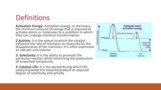
Adsorption is the adhesion of atoms, ions or molecules from a gas, liquid or dissolved
solid to a surface.[1] This process creates a film of the adsorbate on the surface of
the adsorbent. This process differs from absorption, in which a fluid (the absorbate)
is dissolved by or permeates a liquid or solid (the absorbent), respectively.
Adsorption is a surface phenomenon, while absorption involves the whole volume of
the material. The term sorption encompasses both processes, while desorption is the
reverse of it.
Chemisorption is a kind of adsorption which involves a chemical reaction between
the surface and the adsorbate. New chemical bonds are generated at the adsorbant
surface. Examples include macroscopic phenomena that can be very obvious, like
corrosion, and subtler effects associated with heterogeneous catalysis. The strong
interaction between the adsorbate and the substrate surface creates new types of
electronic bonds.](https://image.slidesharecdn.com/reactors-ts-190205154843/85/Troubleshooting-of-Catalytic-Reactors-9-320.jpg)
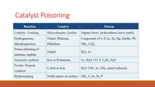
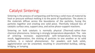
![Troubleshooting of catalytic Reactors
Symptoms Causes
DP higher>design Catalyst degradation/ instrument error/ high gas flow/ sudden coking/ problem left in from
construction or revamp, internal damage.
Rapid decline in
conversion
unfavorable shift in equilibrium at operating temperature, for exothermic reactions/
[sintering]*/ [agglomeration], poisons in feed, temperature runaway
Gradual decline in
conversion
Sample error/ analysis error/ temperature sensor error/ [catalyst activity lost]*/
[maldistribution]*/ [unacceptable temperature profiles]*/ [inadequate heat transfer]*/ wrong
locations of feed, discharge or recycle lines/ faulty design of feed and discharge ports/ wrong
internal baffles and internals/ faulty bed-voidage profiles
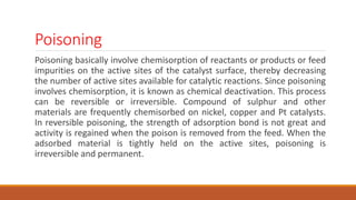
Temperature runaways Change in feed composition, furnace controlled firing, uncontrolled reactions. feed
temperature too high/ [temperature hot spot]*/ cooling water too hot, failure of cooling
media
Local high
temperature/hot spot
[misdistribution of gas flow]*/ instrument error/ extraneous feed component that reacts
exothermically
19](https://image.slidesharecdn.com/reactors-ts-190205154843/85/Troubleshooting-of-Catalytic-Reactors-19-320.jpg)
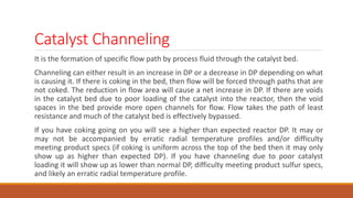
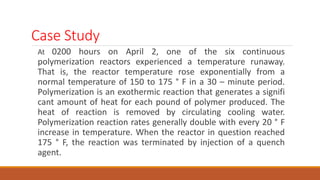
![Troubleshooting of catalytic Reactors
Local low temperature within the
bed
[maldistribution of gas flow]*/ instrument error/ extraneous feed
component that reacts endothermic ally
Exit gas temperature too high instrument error/ control-system malfunction/ fouled reactor coolant
tubes.
Temperature varies axially across
bed
[maldistribution}
Symptom: Soon after startup, temperature of tubewall near top>usual and increasing and perhaps Dp increase
and less conversion than expected or operating temperatures>usual to obtain expected conversion
Cause: inadequate catalyst regeneration/ contamination in feed; for steam reforming sulfur
concentration>specifications/ wrong feed composition; for steam reforming: steam/CH4<7 to 10
20](https://image.slidesharecdn.com/reactors-ts-190205154843/85/Troubleshooting-of-Catalytic-Reactors-20-320.jpg)
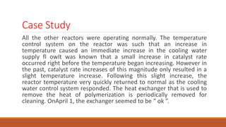
![Troubleshooting of catalytic Reactors
Symptoms Causes
conversions<standard Reduction faulty, bad batch of catalyst/ preconditioning of catalyst faulty/
temperature and pressures incorrectly set/ instrument error for pressure or
temperature
poor selectivity bad batch of catalyst/ preconditioning of catalyst faulty/ temperature and
pressures incorrectly set/ instrument error for pressure or temperature
Dp<expected and conversion<standard maldistribution and axial variation in temperature/ larger size catalyst.
conversion<standard and Dp increasing maldistribution and axial temperatures different]*/ feed precursors present
for polymerization or coking
Dp for this batch of catalyst>previous batch catalyst fines produced during loading/ poor loading
conversion<specifications per unit mass of
catalyst and more side reactions
maldistribution/ faulty inlet distributor/ faulty exit distributor
21](https://image.slidesharecdn.com/reactors-ts-190205154843/85/Troubleshooting-of-Catalytic-Reactors-21-320.jpg)
![Troubleshooting of catalytic Reactors
increased side reactions and
conversion<specification
Catalyst loading not the same in all tubes.
Active species volatized [regeneration faulty]*/ faulty catalyst design for typical reaction temperature/
[hot spots]*.
Agglomeration of packing or catalyst
particles
[temperature hot spots
Carbon buildup inadequate regeneration]*/ [excessive carbon formed]*. [Catalyst selectivity
changes]*: [poisoned catalyst]*/ feed contaminants/ change in feed/ change
in temperature settings
Catalyst activity lost carbon buildup]*/[regeneration faulty]*/ [sintered catalyst]*/ excessive
regeneration temperature/ [poisoned catalyst]*/ [loss of surface area]*/
[agglomeration]*/ [active species volatized
Excessive carbon formed operating intensity above usual/ feed changes/ temperature hot spots.
22](https://image.slidesharecdn.com/reactors-ts-190205154843/85/Troubleshooting-of-Catalytic-Reactors-22-320.jpg)
![Troubleshooting of catalytic Reactors
Symptoms Causes
Dust or corrosive products
from upstream processes
in-line filters not working or not installed/ dust in the atmosphere brought in with air/ air
filters not working or not installed.
Loss of surface area [sintered catalyst]*/ [carbon buildup]*/ [agglomeration
Maldistribution faulty flow-distributor design/ plugging of flow distributors with fine solids, sticky byproducts
or trace polymers/ [sintered catalyst particles]*/ [agglomeration of packing or catalyst
particles]*/ fluid feed velocity too high/ faulty loading of catalyst bed/ incorrect flow collector
at outlet.
Poisoned catalyst Poisons in feed/ flowrate of “counter poison” insufficient/ poison formed from unwanted
reactions.
Reactor instability Control fault/ poor controller tuning/ wrong type of control/ insufficient heat transfer area/
feed temperature exceeds threshold/ coolant temperature exceeds threshold/ coolant
flowrate<threshold/ tube diameter too large
23](https://image.slidesharecdn.com/reactors-ts-190205154843/85/Troubleshooting-of-Catalytic-Reactors-23-320.jpg)


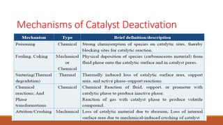
This document provides information about troubleshooting catalytic reactors. It begins with definitions of key terms like catalyst, activity, selectivity, and sintering. It then discusses common symptoms of issues like higher than expected pressure drop, rapid decline in conversion, and temperature runaways. For each symptom, it lists possible causes such as catalyst degradation, poisoning, maldistribution of gas flow, and inadequate heat transfer. It also covers mechanisms of catalyst deactivation like thermal sintering, chemical poisoning, and mechanical fouling. Overall, the document concisely outlines how to diagnose problems in catalytic reactors based on observable symptoms and their potential root causes.


