Download to read offline
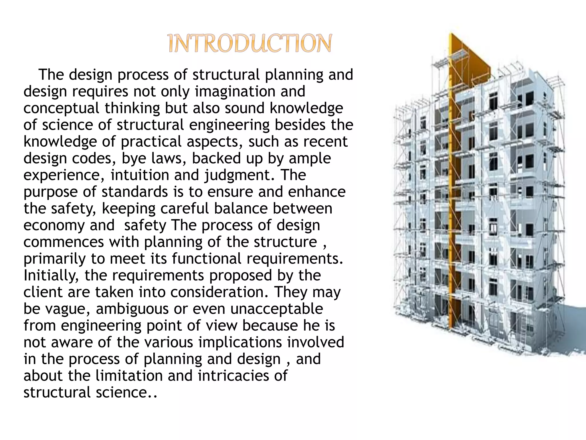
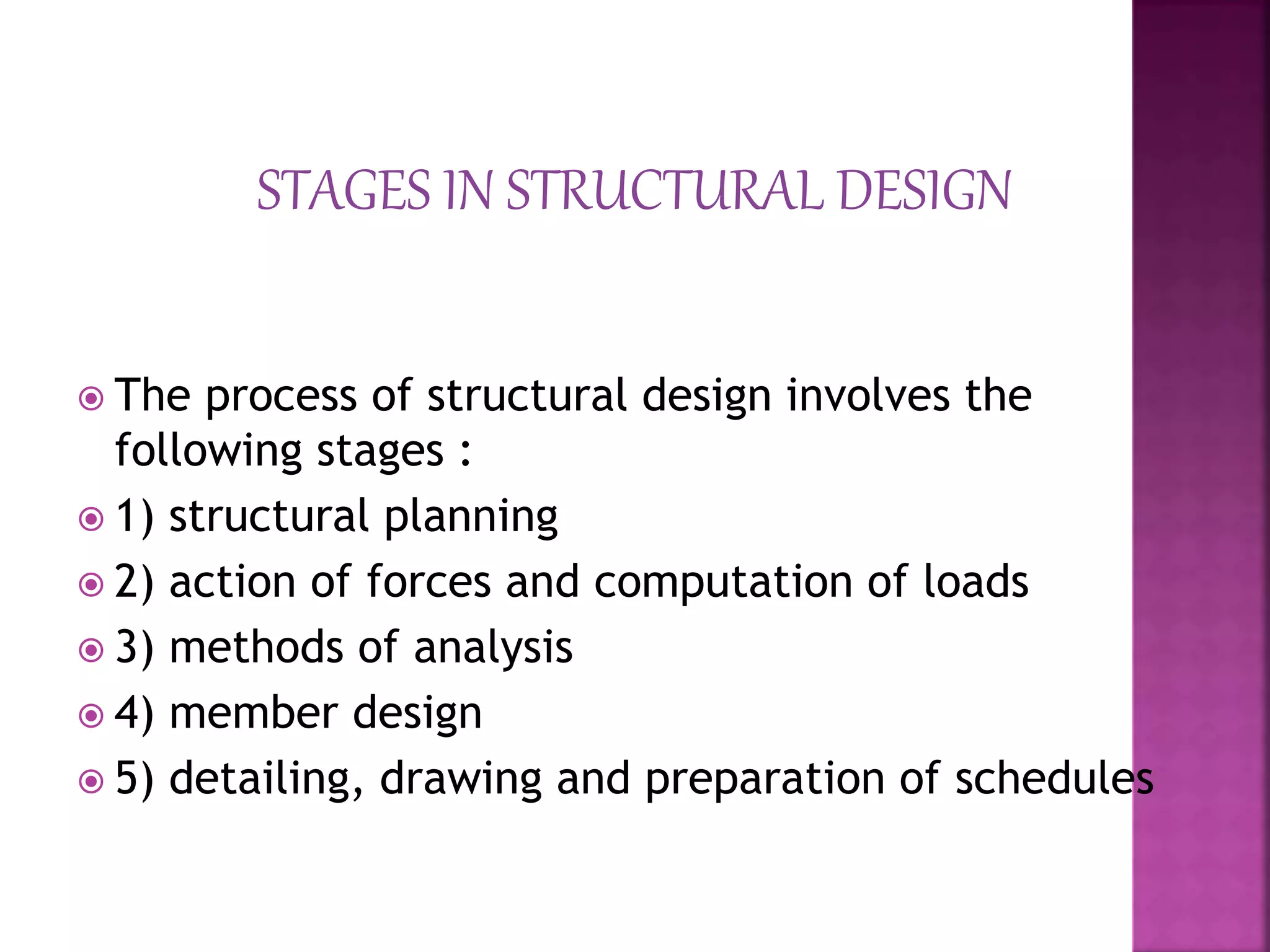
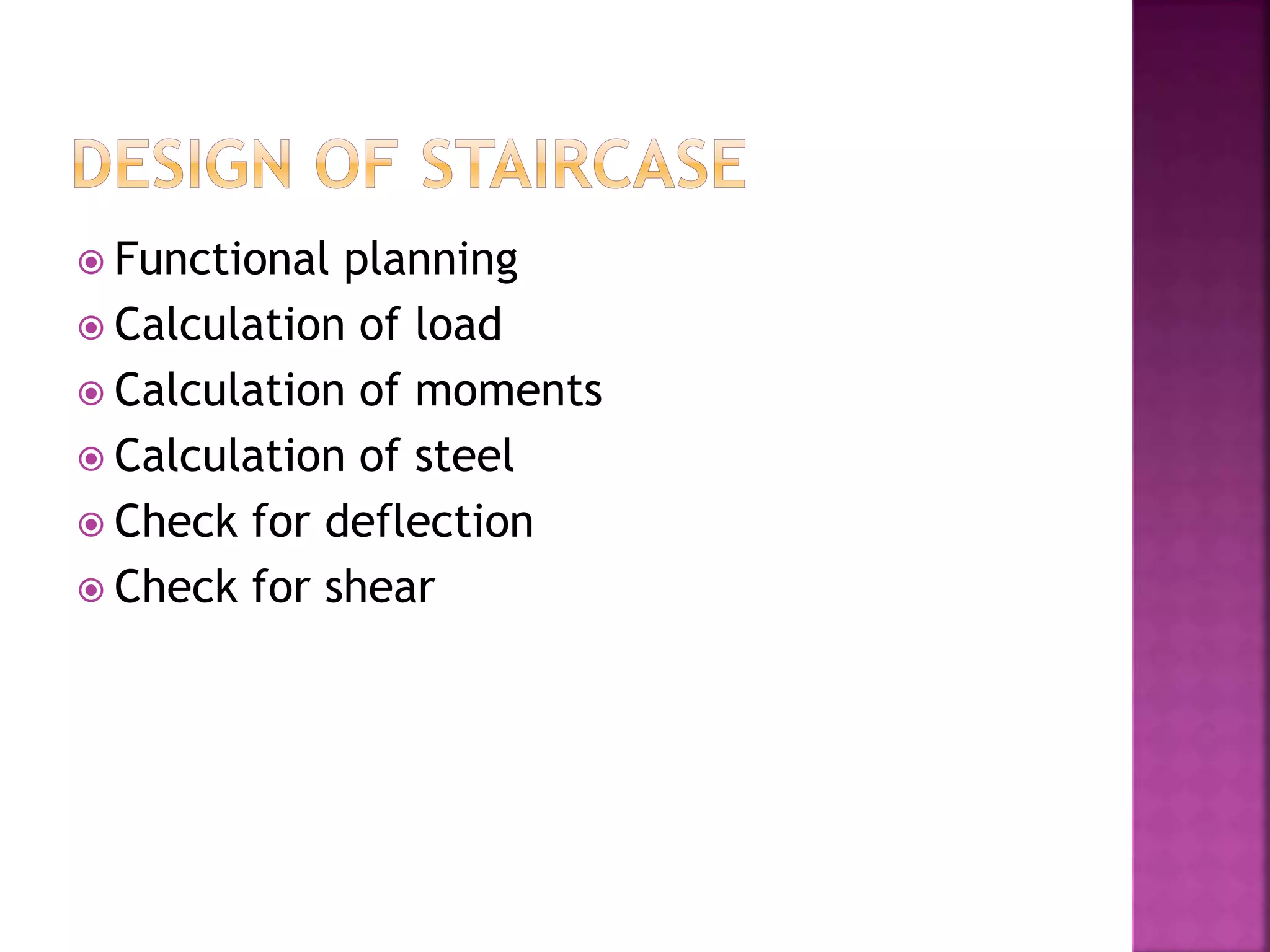
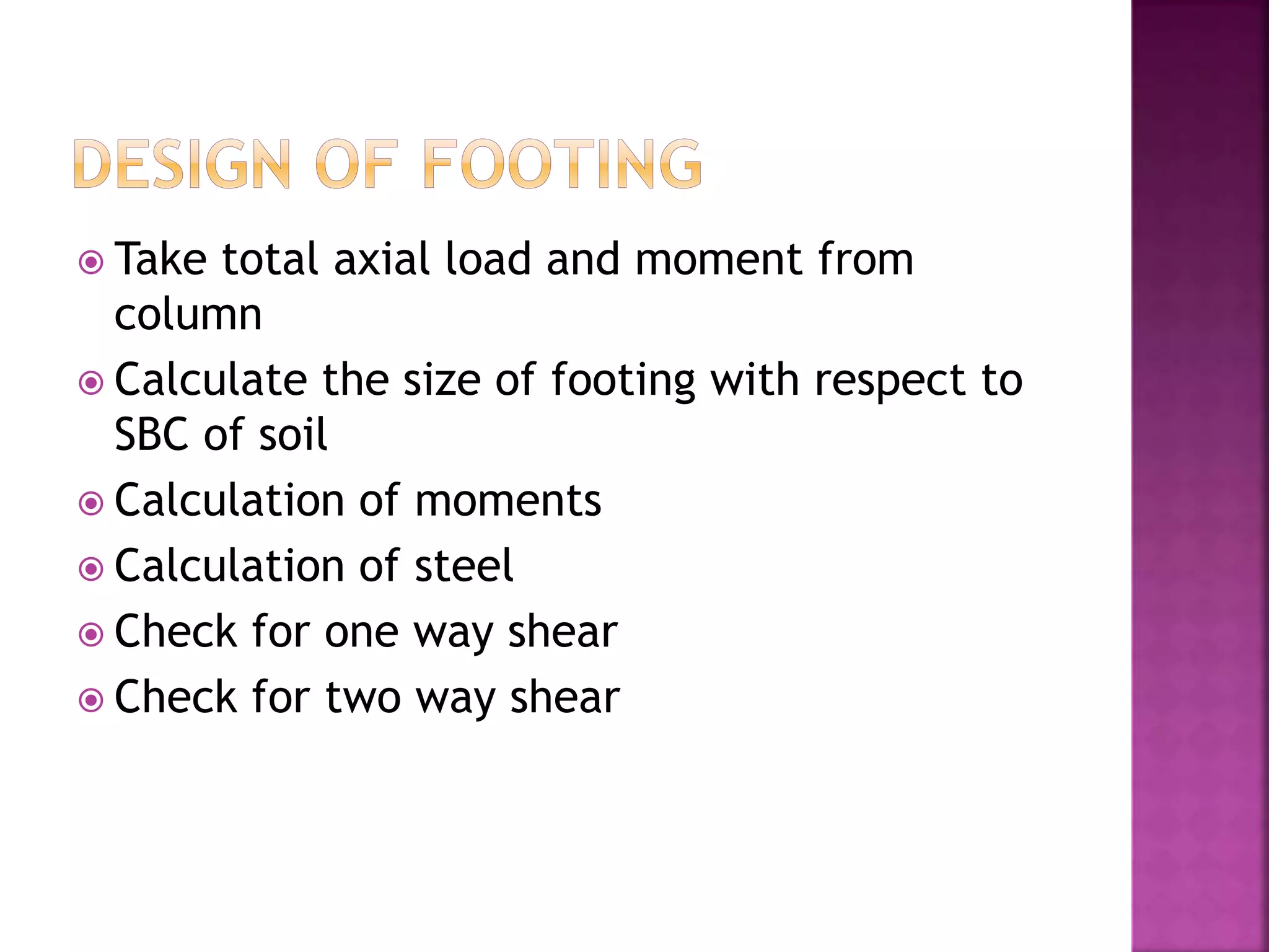
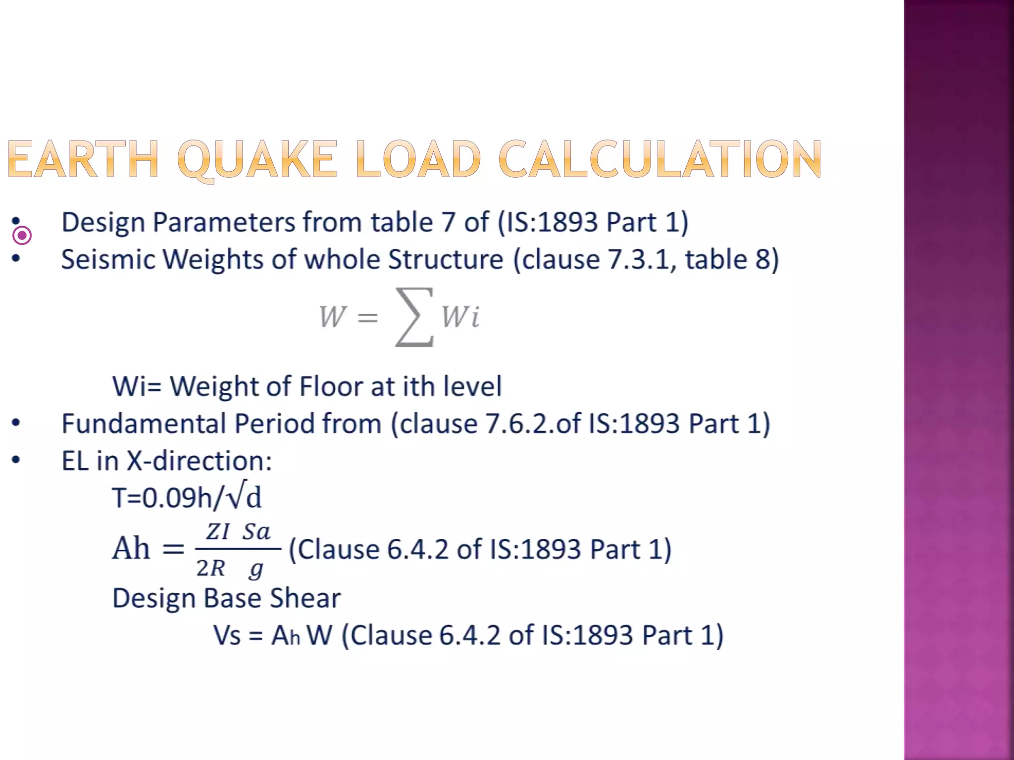

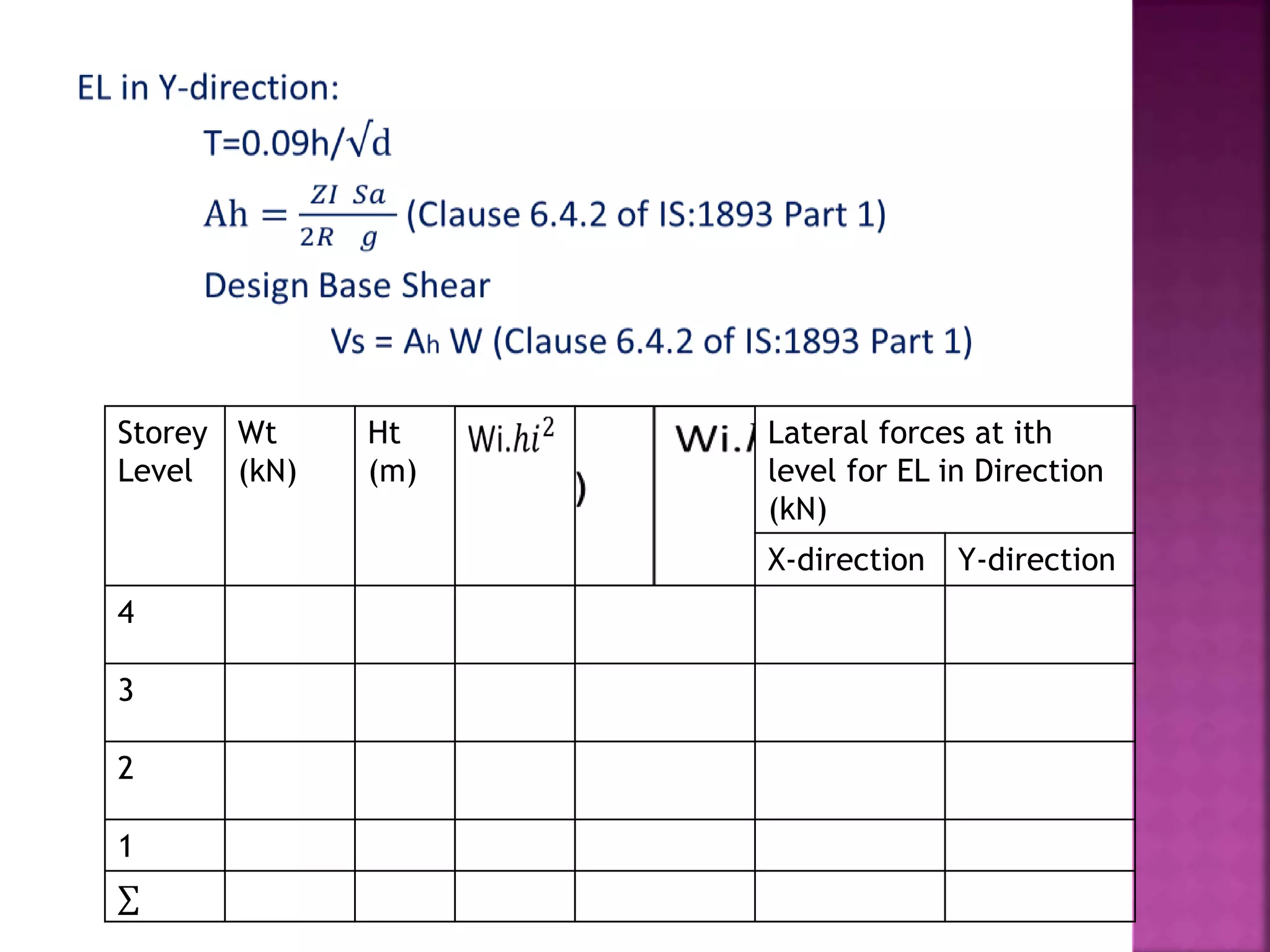


The document provides an overview of the structural design process, emphasizing the need for a blend of imagination, engineering knowledge, and practical experience. It outlines the various stages involved in structural design, including planning, load computation, and detailing, while also discussing specific calculations related to various structural components. Additionally, it highlights the use of software tools like STAAD Pro for modeling and analysis in structural engineering.


