SlideShare a Scribd company logo
1 of 42
Download to read offline
SAP2000 Getting Started Tutorial
Learn how to define materials, sections, grids, and supports with basic modeling concepts for creating
and modifying a concrete bent structure model using a nonprismatic cap beam
Click File>New menu or button/icon to bring up the initial SAP2000 screen where you select
units and choose whether you want to work with grids or one of the templates. For this tutorial,
we will work with Grids, but you will probably want to explore the Quick BrIM options for
modeling of simple bridges later on. Choose Kip, ft, F units and click ‘Grid Only’ option
This screen enables you to define equally spaced grids. Later you will learn how to modify and insert
irregular spaced gridlines. Please type Number of Grid Lines and Grid Spacing as shown. Note how
although we are in Kip-ft units, you can input with architectural units (180” below) at anytime and
SAP2000 will automatically convert to current units after you tab.
Below you will see the default split-screen view. Note that the planar view on the left (X-Y
plan view) is highlighted in blue on the 3D model on the right. As an exercise, click the
down arrow as shown below
By pressing the down arrow, you move to the base, Z = 0, which is highlighted on the
right window. Next, click xz button to switch to elevation view
This changes the view from plan to X-Z elevation. Press the up arrow to move to X-Z
elevation view Y=0 as shown
Double click any gridline to display the Define grid system data dialogue. Here you can add, modify or
delete gridlines at any time. Grids can be added out of numerical sequence and SAP2000 will
automatically reorder them. Select rows and use Edit menu to delete. The ‘Glue to Grid Lines’ option,
when activated, will move and stretch elements associated with a particular gridline that is modified.
Cancel out of this dialogue to return to the main screen.
Go to Define>Materials, press ‘Add New Material Quick’, Material type Concrete and add
f’c 5000 psi concrete and press OK to add this new material. SAP2000 offers several
libraries of materials for steel, concrete, aluminum and cold formed steel. To define a
material not in our standard library, click ‘Add New Material’ button or ‘Add copy of
material’ from an existing material and input material properties
Next we will define frame sections. Go to Define>Section properties>Frame Sections. In
this dialogue, you would click ‘Import New Property’ only if you want to import standard
steel sections from a library (AISC and international libraries of sections). For
nonstandard steel sections such as Plate Girders, nonprismatic sections, or concrete
sections, you use the ‘Add New Property’. Click the ‘Add New property’ button
Select Concrete from the pull down Frame section property type. Please note that any shape in the
steel shape list can be changed to concrete, and conversely, any concrete shape can be modeled as
steel. For example, you can define concrete I/Wide flanges using the steel shape options, or define
solid circular steel rods using the concrete circular shape option.
Click the Rectangular shape option, name the section 3x3 to remember it, change the
Material to 5000 psi concrete which we defined earlier, and input 3ft in both the depth and
width dimensions. Click ‘concrete reinforcement’ to modify or review design parameters.
Then click ‘Set modifiers’ button. Here you can assign reduction factors to EI for analysis
of cracked sections, or assign a multiplier to reduce or increase any section property in
this dialogue. Press OK without changing any factors and press OK again to save this
section
You can type 3”
and tab to
change cover
Commonly used to apply
reduction factors to EI for
cracked sections
By clicking OK, the section is added to the working list on the left. Next, click ‘Add New
Property’ button and click ‘Rectangular’ to add another section. Name it 3x1CapBM and
type in Depth 3ft. And width of 1 foot. Press ‘concrete reinforcement’ button and change
from Column to Beam as shown and press OK
Click OK to accept this new section, click ‘Add New Property’ and ‘Rectangular’ once
more to add another rectangular section. Name it 1.5x1CapBM, type in the dimensions
shown below, click the Concrete reinforcement button and change to beam design type
and press OK twice to add this section to the working list
Next, to review SAP2000’s section designer, click ‘Add new property’ again with Frame
section property type ‘Other’, click Section Designer, then in the SD Section data
dialogue click the ‘Section Designer’ button
Click one of the Caltrans section options and then click on the origin in the middle to draw
it. Next, right click the section to review options and click OK without making any
changes.
Click options to display section properties, P-M-M curves, and moment curvature. The moment
curvature plot also enables you to calculate cracked sections based on load if you select the ‘Caltrans
idealized model’ option. Click Done and Ok until you exit the section designer as we wanted to
introduce the SD capability within this tutorial, but we will not use a SD section for this exercise.
Click ‘Add new property’ button once more, but this time click Concrete ‘Circular’ type,
name it 15”CircularCOL, type 15” and then press tab to have SAP2000 convert to current
ft. units. Click OK twice to accept and save defined sections. Click the save button and
name the model Tutorial1
You should still have a split screen view as shown below with X-Z planar view on the left. If not, click
your left window to make it active, then click the xz button to change view and up/down arrow keys
if you need to adjust further. Next, click ‘Draw frame/cable element’ button as shown and click the
section to change the section property to 15”CircularCOL in the pop-up properties box.
In X-Z view window, click once on the bottom left grid intersection and then click up to the
top left grid intersection in order to draw the column. Next, right mouse click to lift your
cursor to draw another column on the right side. Click once on the bottom right
intersection and complete the column by clicking on the top right grid intersection. Next,
press Esc key on your keyboard or the select button/icon to switch to select mode
Draw column with two mouse
clicks
Elevation view
Holding your left mouse key down, drag your mouse to window around the base of the
two columns in order to select bottom joints as shown
Next, use the Assign menu>Joint>Restraints to add fixed restraints as shown. Press OK
Click ‘Draw frame/cable element’ button, change Section property to 3x1CapBM and click
twice to draw the cap beam as shown. Click ‘Set Display options’ button and checkbox
‘Extrude view’ option and press OK
The extruded view enables you to see a proportional rendered view of the model. You can see that we
have basic centerline connection. By clicking in a window to make it ‘active’, you can display extruded
view in 1 window or all windows. Click ‘Set display options’ box once more, uncheck the ‘extruded
view’ option and select the beam by clicking on it as shown.
Selected beam displays as dotted line
Go to Assign>Frame loads>Point to assign point loads along the length of the beam. Using Relative
percentage distance, change the 2nd distance to .2 and 3rd distance to .8 and input a 100 Kip load for 2
and 110 Kip load for 3 and press OK to assign these loads in the DEAD load pattern. By clicking the +
button next to the load pattern name, you could define additional load pattern cases to assign the load
to. Alternatively, you could Define load patterns and combos under the Define menu before assigning
loads
In order consider p-delta effects, go to Define>Load cases, click DEAD and press the ‘Add copy of
load case’ button and checkbox Nonlinear and P-delta as shown below and press OK twice to accept.
Alternatively, we could have modified the DEAD case, but by making a copy of it, we can compare
results between the P-delta DEAD case and the DEAD case without P-delta in the same analysis
Press F5 on your keyboard to run the analysis and press ‘Run now’ button as shown.
After the analysis has completed, click the arrow next to the ‘Show forces/stresses’
button as shown and select Moment 3-3 to interactively display major moment.
You can then right click individual frames for results as shown, toggling between cases
and results options. Press Done.
Use Display menu>Show tables to generate output tables and input summaries. You can
select which load patterns and cases to include, which joints and elements you want to
report and which reports you want to generate
Using the table form, you can go to the File menu>Export current table and export to
Excel or Access. You can utilize the Format-Filter-Sort menu option to format and to sort
by min/max values in any specified direction.
To perform an ACI 318-05 design check, go to Design menu>Concrete Frame
design>View/Revise preferences to specify design parameters. Then go to Define
menu>Load Combinations. Here you can define your own factored load combos, or let
SAP2000 generate them automatically based on your selected design code.
As an alternative to defining P-delta cases one-at-a-time as we did before, SAP2000 offers an option to
automatically convert load combos into nonlinear P-delta cases by clicking the ‘Convert Combos to
Nonlinear cases’ button on the load combo screen, then select/highlight the combos to be converted. To
do a concrete design, first run an analysis. After the analysis completes, then run a concrete design by
clicking the ‘Start concrete design/check’ button . After the design completes, you can right click
individual frames for design results, or use the Design menu>Concrete frame design>Display design info,
or use Display menu>Show tables to print and sort results
Select load combos to convert
into nonlinear P-delta cases
Close the output forms, unlock the model, by clicking the unlock button ,say OK to the
unlock warning. Next we’re going to define a nonprismatic cap beam, so go to
Define>Section properties>Frame sections, click ‘Add new property’, ‘Other’ frame
section property type and click ‘Nonprismatic’
Accept the default VAR1 section name and type the values shown below for sections,
lengths and length type. SAP2000 lets you define the length type by variable percentage
or absolute length using current units (ft in this example). Press OK twice to return to the
model
Select the existing beam and press the Del (delete) key on your keyboard. Next, click the ‘Draw
special joint’ button, type -3(feet) in the X direction and click the top of the left side column to draw a
joint 3 feet away as shown. You may or may not have to add the Draw special joint button to your
palette using the ‘More buttons’ arrow
Draw special
Joint button
Add
more
buttons
Next, change offset dimension to (+) 3 feet in the X direction and click the top of the right column to
add another joint. Next, click ‘Draw frame/cable element’ button , change section to VAR1 with
continuous connection and connect the dots by clicking once on the special joint on the left and then
complete the beam by clicking on the special joint on the right as shown. SAP2000’s object based
modeling will automatically connect the columns to the beam with no further meshing required. Special
joints with snap tools can also be used to add joints on frames to assign joint loads without manually
dividing the frame
Press Esc key or click select arrow button to exit draw mode. Click the ‘Set display
options’ menu and checkbox extrude view for the planar view. Hold down your left mouse
key and drag right to left while intersecting the beam in order to select
Next, use the main menu and go to Assign>Frame>Insertion point. Then press the F1 key on your
keyboard to read more about this feature, which lets you assign cardinal point offsets + additional
offsets. Please select cardinal point 8 (top center) with additional 3 ft. joint offsets in the local 2
direction as shown. Local 2 direction = Z in global coordinate system for this beam. Press OK
To delete restraints, you need to select the joints where restraints are assigned by windowing around
the base of the bent structure, then Assign>Joint>Restraints and click the black dot to assign a null
which deletes the restraints. Next, go to Define menu>Section properties>Link/support properties
where you can define other supports known as “links”, which can be 1 point or 2 point links. Click ‘Add
new property’ button to review options. Below right is the multi-linear plastic spring which is commonly
used for nonlinear pile/soil interaction to define P-Y and T-Z curves
There are also nonlinear link property options for gap springs, base isolators (friction bearing and
elastomer), nonlinear viscous damper with velocity exponent with linear options to assign dashpots C
and linear springs K. Under define menu you will also see the option to define frequency dependent K
and C for dynamic analysis, as geotechnical data may report soil properties as a function of frequency.
Links can be assigned as point supports, or on a per lineal unit basis on frame elements, or per area
basis for shells and solid finite elements. In this manner, you can easily model piles explicitly using
circular or rectangular frame elements, then assign the link as a frame spring/link assignment.
We’ll end the tutorial here by demonstrating two more options: Replicate commands, rotating frame
local axis, and assignment of shear and moment releases. Check the bottom right portion of your
screen to make sure you’re in Kip-ft units, click the ‘Select all’ button to select and then
Edit>Replicate. Here you can copy and paste in linear, radial or mirror fashion. If you want to rotate all
or a portion of the entire structure, you do it with Replicate, just checkbox the ‘Delete Original Object’
box
To rotate local axis of frames or to assign moment and/or shear releases, first select frames by
clicking them or using one of the Select menu options, then Assign>Frame>Local axes and type an
angle in order to rotate local axes. If you want to assign releases, choose the
Assign>Frame>Releases/Partial fixity option shown below on the right
There are several good Watch & Learn video tutorials on our website here
http://www.csiberkeley.com/Support_WL_SAP.html which cover bridge modeling and
other features of SAP2000. These videos are good tools to help you get started while
minimizing the learning curve. Also, the SAP2000 Help menu enables you to access user
manuals and other documentation.
Please feel free to contact me if you have feedback or suggestions regarding this tutorial
or if you have SAP2000 modeling questions. I’m here to help new users get started:
Darrell Foster
CSI Houston, TX office
Tel: 713-533-4420
Computers & Structures, Inc.
TECHNOLOGY FOR A BETTER WORLD
darrell@csiberkeley.com
www.csiberkeley.com

More Related Content

What's hot

How to create a Composite FEM via Hypermesh
How to create a Composite FEM via HypermeshHow to create a Composite FEM via Hypermesh
How to create a Composite FEM via HypermeshNorm Lamar
 
Lecture 10: introduction to computer
Lecture 10: introduction to computerLecture 10: introduction to computer
Lecture 10: introduction to computerSultan Omar Shige
 
Finite Element Simulation with Ansys Workbench 14
Finite Element Simulation with Ansys Workbench 14Finite Element Simulation with Ansys Workbench 14
Finite Element Simulation with Ansys Workbench 14Prem Prakash Pandey
 
DISEÑO DE MOLDES - 97471744 vero-visi-mould-tutorial
DISEÑO DE MOLDES - 97471744 vero-visi-mould-tutorialDISEÑO DE MOLDES - 97471744 vero-visi-mould-tutorial
DISEÑO DE MOLDES - 97471744 vero-visi-mould-tutorialFrankey Sun
 
Coord transform 082014
Coord transform 082014Coord transform 082014
Coord transform 082014PramodPandit9
 
Sheet solutions 2009
Sheet solutions 2009Sheet solutions 2009
Sheet solutions 2009Hien Dinh
 
ArcGIS for Desktop Tips and Shortcuts
ArcGIS for Desktop Tips and ShortcutsArcGIS for Desktop Tips and Shortcuts
ArcGIS for Desktop Tips and ShortcutsEsri
 
Civil 3d alignments and profile traning
Civil 3d alignments and profile traningCivil 3d alignments and profile traning
Civil 3d alignments and profile traningmrdvirus
 
Creating an excel chart
Creating an excel chartCreating an excel chart
Creating an excel chartmeeker1987
 
Using AutoDesk Inventor to create a Trinket box
Using AutoDesk Inventor to create a Trinket boxUsing AutoDesk Inventor to create a Trinket box
Using AutoDesk Inventor to create a Trinket boxkrysia
 
Using AutoDesk Inventor to assemble a Trinket box
Using AutoDesk Inventor to assemble a Trinket boxUsing AutoDesk Inventor to assemble a Trinket box
Using AutoDesk Inventor to assemble a Trinket boxkrysia
 

What's hot (20)

How to create a Composite FEM via Hypermesh
How to create a Composite FEM via HypermeshHow to create a Composite FEM via Hypermesh
How to create a Composite FEM via Hypermesh
 
Lecture 10: introduction to computer
Lecture 10: introduction to computerLecture 10: introduction to computer
Lecture 10: introduction to computer
 
Acad10 tips and_tricks
Acad10 tips and_tricksAcad10 tips and_tricks
Acad10 tips and_tricks
 
New manual
New manualNew manual
New manual
 
Finite Element Simulation with Ansys Workbench 14
Finite Element Simulation with Ansys Workbench 14Finite Element Simulation with Ansys Workbench 14
Finite Element Simulation with Ansys Workbench 14
 
Read me stack up copy
Read me   stack up copyRead me   stack up copy
Read me stack up copy
 
Visi progress
Visi progressVisi progress
Visi progress
 
knuckle Joint 2D drawing AutoCAD 2019
knuckle Joint 2D drawing AutoCAD 2019knuckle Joint 2D drawing AutoCAD 2019
knuckle Joint 2D drawing AutoCAD 2019
 
DISEÑO DE MOLDES - 97471744 vero-visi-mould-tutorial
DISEÑO DE MOLDES - 97471744 vero-visi-mould-tutorialDISEÑO DE MOLDES - 97471744 vero-visi-mould-tutorial
DISEÑO DE MOLDES - 97471744 vero-visi-mould-tutorial
 
Coord transform 082014
Coord transform 082014Coord transform 082014
Coord transform 082014
 
Sheet solutions 2009
Sheet solutions 2009Sheet solutions 2009
Sheet solutions 2009
 
ArcGIS for Desktop Tips and Shortcuts
ArcGIS for Desktop Tips and ShortcutsArcGIS for Desktop Tips and Shortcuts
ArcGIS for Desktop Tips and Shortcuts
 
Civil 3d alignments and profile traning
Civil 3d alignments and profile traningCivil 3d alignments and profile traning
Civil 3d alignments and profile traning
 
Creating an excel chart
Creating an excel chartCreating an excel chart
Creating an excel chart
 
Catia Part05
Catia Part05Catia Part05
Catia Part05
 
3 d autocad_2009
3 d autocad_20093 d autocad_2009
3 d autocad_2009
 
Using AutoDesk Inventor to create a Trinket box
Using AutoDesk Inventor to create a Trinket boxUsing AutoDesk Inventor to create a Trinket box
Using AutoDesk Inventor to create a Trinket box
 
Using AutoDesk Inventor to assemble a Trinket box
Using AutoDesk Inventor to assemble a Trinket boxUsing AutoDesk Inventor to assemble a Trinket box
Using AutoDesk Inventor to assemble a Trinket box
 
Cad standards for biggner
Cad standards for biggner Cad standards for biggner
Cad standards for biggner
 
Profile milling
Profile millingProfile milling
Profile milling
 

Similar to Concrete bent with_nonprismatic_cap_beam

SAP2000 Cold-formed steel truss.pdf
SAP2000 Cold-formed steel truss.pdfSAP2000 Cold-formed steel truss.pdf
SAP2000 Cold-formed steel truss.pdfstnOnurBaktr
 
Software application for qs material standard rate
Software application for qs   material  standard rateSoftware application for qs   material  standard rate
Software application for qs material standard rateFarah Sham
 
Xmastcamcribboard
XmastcamcribboardXmastcamcribboard
Xmastcamcribboarddoglupo
 
Workshop10 creep-jop
Workshop10 creep-jopWorkshop10 creep-jop
Workshop10 creep-jopmmd110
 
Civil 3d Workflow_NOLOGO
Civil 3d Workflow_NOLOGOCivil 3d Workflow_NOLOGO
Civil 3d Workflow_NOLOGOGary Cassidy
 
Modeling the Building.pptx
Modeling the Building.pptxModeling the Building.pptx
Modeling the Building.pptxLeahcim Nolyab
 
How to design a report with fine report reporting tool
How to design a report with  fine report reporting toolHow to design a report with  fine report reporting tool
How to design a report with fine report reporting toolFineReport Reporting Tool
 
StaadPro Manual by yousuf dinar
StaadPro Manual by yousuf dinarStaadPro Manual by yousuf dinar
StaadPro Manual by yousuf dinarYousuf Dinar
 
Cis407 a ilab 2 web application development devry university
Cis407 a ilab 2 web application development devry universityCis407 a ilab 2 web application development devry university
Cis407 a ilab 2 web application development devry universitylhkslkdh89009
 
Introductory tutorial etab2016
Introductory tutorial etab2016Introductory tutorial etab2016
Introductory tutorial etab2016TPHCM
 
Sheet metal design in Solid Edge.docx
Sheet metal design in Solid Edge.docxSheet metal design in Solid Edge.docx
Sheet metal design in Solid Edge.docxSomashekar S.M
 
WinEst As 1. Es2. Tassignment stInfo (Esti.docx
WinEst As 1. Es2. Tassignment stInfo (Esti.docxWinEst As 1. Es2. Tassignment stInfo (Esti.docx
WinEst As 1. Es2. Tassignment stInfo (Esti.docxalanfhall8953
 
Workshop1 cant-beam
Workshop1 cant-beamWorkshop1 cant-beam
Workshop1 cant-beammmd110
 
Thermal Analysis in Hypermesh (Conduction, Convention and Thermal Expansion)
Thermal Analysis in Hypermesh (Conduction, Convention and Thermal Expansion)Thermal Analysis in Hypermesh (Conduction, Convention and Thermal Expansion)
Thermal Analysis in Hypermesh (Conduction, Convention and Thermal Expansion)Akshay Mistri
 
Microsoft Project 2003 Configuration Training Level 2 Itvamp 2007
Microsoft Project 2003 Configuration Training Level 2 Itvamp 2007Microsoft Project 2003 Configuration Training Level 2 Itvamp 2007
Microsoft Project 2003 Configuration Training Level 2 Itvamp 2007ITVAMP, LLC
 
Data presentation and reporting cognos tm1
Data presentation and reporting cognos tm1Data presentation and reporting cognos tm1
Data presentation and reporting cognos tm1veeracynixit
 
A. Lab # BSBA BIS245A-7B. Lab 7 of 7 Database Navigation.docx
A. Lab #  BSBA BIS245A-7B. Lab 7 of 7  Database Navigation.docxA. Lab #  BSBA BIS245A-7B. Lab 7 of 7  Database Navigation.docx
A. Lab # BSBA BIS245A-7B. Lab 7 of 7 Database Navigation.docxransayo
 

Similar to Concrete bent with_nonprismatic_cap_beam (20)

SAP2000 Cold-formed steel truss.pdf
SAP2000 Cold-formed steel truss.pdfSAP2000 Cold-formed steel truss.pdf
SAP2000 Cold-formed steel truss.pdf
 
Software application for qs material standard rate
Software application for qs   material  standard rateSoftware application for qs   material  standard rate
Software application for qs material standard rate
 
Xmastcamcribboard
XmastcamcribboardXmastcamcribboard
Xmastcamcribboard
 
Workshop10 creep-jop
Workshop10 creep-jopWorkshop10 creep-jop
Workshop10 creep-jop
 
Civil 3d workflow
Civil 3d workflowCivil 3d workflow
Civil 3d workflow
 
Civil 3d Workflow_NOLOGO
Civil 3d Workflow_NOLOGOCivil 3d Workflow_NOLOGO
Civil 3d Workflow_NOLOGO
 
Modeling the Building.pptx
Modeling the Building.pptxModeling the Building.pptx
Modeling the Building.pptx
 
How to design a report with fine report reporting tool
How to design a report with  fine report reporting toolHow to design a report with  fine report reporting tool
How to design a report with fine report reporting tool
 
Ms Excel AZC
Ms Excel AZCMs Excel AZC
Ms Excel AZC
 
StaadPro Manual by yousuf dinar
StaadPro Manual by yousuf dinarStaadPro Manual by yousuf dinar
StaadPro Manual by yousuf dinar
 
Cis407 a ilab 2 web application development devry university
Cis407 a ilab 2 web application development devry universityCis407 a ilab 2 web application development devry university
Cis407 a ilab 2 web application development devry university
 
Introductory tutorial etab2016
Introductory tutorial etab2016Introductory tutorial etab2016
Introductory tutorial etab2016
 
Sheet metal design in Solid Edge.docx
Sheet metal design in Solid Edge.docxSheet metal design in Solid Edge.docx
Sheet metal design in Solid Edge.docx
 
WinEst As 1. Es2. Tassignment stInfo (Esti.docx
WinEst As 1. Es2. Tassignment stInfo (Esti.docxWinEst As 1. Es2. Tassignment stInfo (Esti.docx
WinEst As 1. Es2. Tassignment stInfo (Esti.docx
 
Workshop1 cant-beam
Workshop1 cant-beamWorkshop1 cant-beam
Workshop1 cant-beam
 
Thermal Analysis in Hypermesh (Conduction, Convention and Thermal Expansion)
Thermal Analysis in Hypermesh (Conduction, Convention and Thermal Expansion)Thermal Analysis in Hypermesh (Conduction, Convention and Thermal Expansion)
Thermal Analysis in Hypermesh (Conduction, Convention and Thermal Expansion)
 
Microsoft Project 2003 Configuration Training Level 2 Itvamp 2007
Microsoft Project 2003 Configuration Training Level 2 Itvamp 2007Microsoft Project 2003 Configuration Training Level 2 Itvamp 2007
Microsoft Project 2003 Configuration Training Level 2 Itvamp 2007
 
Microsoft excel part 2
Microsoft excel part 2Microsoft excel part 2
Microsoft excel part 2
 
Data presentation and reporting cognos tm1
Data presentation and reporting cognos tm1Data presentation and reporting cognos tm1
Data presentation and reporting cognos tm1
 
A. Lab # BSBA BIS245A-7B. Lab 7 of 7 Database Navigation.docx
A. Lab #  BSBA BIS245A-7B. Lab 7 of 7  Database Navigation.docxA. Lab #  BSBA BIS245A-7B. Lab 7 of 7  Database Navigation.docx
A. Lab # BSBA BIS245A-7B. Lab 7 of 7 Database Navigation.docx
 

Recently uploaded

NO1 Trending kala jadu Love Marriage Black Magic Punjab Powerful Black Magic ...
NO1 Trending kala jadu Love Marriage Black Magic Punjab Powerful Black Magic ...NO1 Trending kala jadu Love Marriage Black Magic Punjab Powerful Black Magic ...
NO1 Trending kala jadu Love Marriage Black Magic Punjab Powerful Black Magic ...Amil baba
 
SD_The MATATAG Curriculum Training Design.pptx
SD_The MATATAG Curriculum Training Design.pptxSD_The MATATAG Curriculum Training Design.pptx
SD_The MATATAG Curriculum Training Design.pptxjanettecruzeiro1
 
call girls in Harsh Vihar (DELHI) 🔝 >༒9953330565🔝 genuine Escort Service 🔝✔️✔️
call girls in Harsh Vihar (DELHI) 🔝 >༒9953330565🔝 genuine Escort Service 🔝✔️✔️call girls in Harsh Vihar (DELHI) 🔝 >༒9953330565🔝 genuine Escort Service 🔝✔️✔️
call girls in Harsh Vihar (DELHI) 🔝 >༒9953330565🔝 genuine Escort Service 🔝✔️✔️9953056974 Low Rate Call Girls In Saket, Delhi NCR
 
SCRIP Lua HTTP PROGRACMACION PLC WECON CA
SCRIP Lua HTTP PROGRACMACION PLC  WECON CASCRIP Lua HTTP PROGRACMACION PLC  WECON CA
SCRIP Lua HTTP PROGRACMACION PLC WECON CANestorGamez6
 
Fashion trends before and after covid.pptx
Fashion trends before and after covid.pptxFashion trends before and after covid.pptx
Fashion trends before and after covid.pptxVanshNarang19
 
DragonBall PowerPoint Template for demo.pptx
DragonBall PowerPoint Template for demo.pptxDragonBall PowerPoint Template for demo.pptx
DragonBall PowerPoint Template for demo.pptxmirandajeremy200221
 
VIP Call Girls Service Mehdipatnam Hyderabad Call +91-8250192130
VIP Call Girls Service Mehdipatnam Hyderabad Call +91-8250192130VIP Call Girls Service Mehdipatnam Hyderabad Call +91-8250192130
VIP Call Girls Service Mehdipatnam Hyderabad Call +91-8250192130Suhani Kapoor
 
Cheap Rate Call girls Kalkaji 9205541914 shot 1500 night
Cheap Rate Call girls Kalkaji 9205541914 shot 1500 nightCheap Rate Call girls Kalkaji 9205541914 shot 1500 night
Cheap Rate Call girls Kalkaji 9205541914 shot 1500 nightDelhi Call girls
 
CALL ON ➥8923113531 🔝Call Girls Kalyanpur Lucknow best Female service 🧵
CALL ON ➥8923113531 🔝Call Girls Kalyanpur Lucknow best Female service  🧵CALL ON ➥8923113531 🔝Call Girls Kalyanpur Lucknow best Female service  🧵
CALL ON ➥8923113531 🔝Call Girls Kalyanpur Lucknow best Female service 🧵anilsa9823
 
Call Girls in Kalkaji Delhi 8264348440 call girls ❤️
Call Girls in Kalkaji Delhi 8264348440 call girls ❤️Call Girls in Kalkaji Delhi 8264348440 call girls ❤️
Call Girls in Kalkaji Delhi 8264348440 call girls ❤️soniya singh
 
The history of music videos a level presentation
The history of music videos a level presentationThe history of music videos a level presentation
The history of music videos a level presentationamedia6
 
Raj Nagar Extension Call Girls 9711199012 WhatsApp No, Delhi Escorts in Raj N...
Raj Nagar Extension Call Girls 9711199012 WhatsApp No, Delhi Escorts in Raj N...Raj Nagar Extension Call Girls 9711199012 WhatsApp No, Delhi Escorts in Raj N...
Raj Nagar Extension Call Girls 9711199012 WhatsApp No, Delhi Escorts in Raj N...ankitnayak356677
 
Chapter 19_DDA_TOD Policy_First Draft 2012.pdf
Chapter 19_DDA_TOD Policy_First Draft 2012.pdfChapter 19_DDA_TOD Policy_First Draft 2012.pdf
Chapter 19_DDA_TOD Policy_First Draft 2012.pdfParomita Roy
 
VIP Call Girls Service Bhagyanagar Hyderabad Call +91-8250192130
VIP Call Girls Service Bhagyanagar Hyderabad Call +91-8250192130VIP Call Girls Service Bhagyanagar Hyderabad Call +91-8250192130
VIP Call Girls Service Bhagyanagar Hyderabad Call +91-8250192130Suhani Kapoor
 
The_Canvas_of_Creative_Mastery_Newsletter_April_2024_Version.pdf
The_Canvas_of_Creative_Mastery_Newsletter_April_2024_Version.pdfThe_Canvas_of_Creative_Mastery_Newsletter_April_2024_Version.pdf
The_Canvas_of_Creative_Mastery_Newsletter_April_2024_Version.pdfAmirYakdi
 
Best VIP Call Girls Noida Sector 44 Call Me: 8448380779
Best VIP Call Girls Noida Sector 44 Call Me: 8448380779Best VIP Call Girls Noida Sector 44 Call Me: 8448380779
Best VIP Call Girls Noida Sector 44 Call Me: 8448380779Delhi Call girls
 
NO1 Famous Amil Baba In Karachi Kala Jadu In Karachi Amil baba In Karachi Add...
NO1 Famous Amil Baba In Karachi Kala Jadu In Karachi Amil baba In Karachi Add...NO1 Famous Amil Baba In Karachi Kala Jadu In Karachi Amil baba In Karachi Add...
NO1 Famous Amil Baba In Karachi Kala Jadu In Karachi Amil baba In Karachi Add...Amil baba
 

Recently uploaded (20)

NO1 Trending kala jadu Love Marriage Black Magic Punjab Powerful Black Magic ...
NO1 Trending kala jadu Love Marriage Black Magic Punjab Powerful Black Magic ...NO1 Trending kala jadu Love Marriage Black Magic Punjab Powerful Black Magic ...
NO1 Trending kala jadu Love Marriage Black Magic Punjab Powerful Black Magic ...
 
SD_The MATATAG Curriculum Training Design.pptx
SD_The MATATAG Curriculum Training Design.pptxSD_The MATATAG Curriculum Training Design.pptx
SD_The MATATAG Curriculum Training Design.pptx
 
call girls in Harsh Vihar (DELHI) 🔝 >༒9953330565🔝 genuine Escort Service 🔝✔️✔️
call girls in Harsh Vihar (DELHI) 🔝 >༒9953330565🔝 genuine Escort Service 🔝✔️✔️call girls in Harsh Vihar (DELHI) 🔝 >༒9953330565🔝 genuine Escort Service 🔝✔️✔️
call girls in Harsh Vihar (DELHI) 🔝 >༒9953330565🔝 genuine Escort Service 🔝✔️✔️
 
SCRIP Lua HTTP PROGRACMACION PLC WECON CA
SCRIP Lua HTTP PROGRACMACION PLC  WECON CASCRIP Lua HTTP PROGRACMACION PLC  WECON CA
SCRIP Lua HTTP PROGRACMACION PLC WECON CA
 
Fashion trends before and after covid.pptx
Fashion trends before and after covid.pptxFashion trends before and after covid.pptx
Fashion trends before and after covid.pptx
 
young call girls in Vivek Vihar🔝 9953056974 🔝 Delhi escort Service
young call girls in Vivek Vihar🔝 9953056974 🔝 Delhi escort Serviceyoung call girls in Vivek Vihar🔝 9953056974 🔝 Delhi escort Service
young call girls in Vivek Vihar🔝 9953056974 🔝 Delhi escort Service
 
DragonBall PowerPoint Template for demo.pptx
DragonBall PowerPoint Template for demo.pptxDragonBall PowerPoint Template for demo.pptx
DragonBall PowerPoint Template for demo.pptx
 
VIP Call Girls Service Mehdipatnam Hyderabad Call +91-8250192130
VIP Call Girls Service Mehdipatnam Hyderabad Call +91-8250192130VIP Call Girls Service Mehdipatnam Hyderabad Call +91-8250192130
VIP Call Girls Service Mehdipatnam Hyderabad Call +91-8250192130
 
young call girls in Pandav nagar 🔝 9953056974 🔝 Delhi escort Service
young call girls in Pandav nagar 🔝 9953056974 🔝 Delhi escort Serviceyoung call girls in Pandav nagar 🔝 9953056974 🔝 Delhi escort Service
young call girls in Pandav nagar 🔝 9953056974 🔝 Delhi escort Service
 
Cheap Rate Call girls Kalkaji 9205541914 shot 1500 night
Cheap Rate Call girls Kalkaji 9205541914 shot 1500 nightCheap Rate Call girls Kalkaji 9205541914 shot 1500 night
Cheap Rate Call girls Kalkaji 9205541914 shot 1500 night
 
CALL ON ➥8923113531 🔝Call Girls Kalyanpur Lucknow best Female service 🧵
CALL ON ➥8923113531 🔝Call Girls Kalyanpur Lucknow best Female service  🧵CALL ON ➥8923113531 🔝Call Girls Kalyanpur Lucknow best Female service  🧵
CALL ON ➥8923113531 🔝Call Girls Kalyanpur Lucknow best Female service 🧵
 
Call Girls in Kalkaji Delhi 8264348440 call girls ❤️
Call Girls in Kalkaji Delhi 8264348440 call girls ❤️Call Girls in Kalkaji Delhi 8264348440 call girls ❤️
Call Girls in Kalkaji Delhi 8264348440 call girls ❤️
 
The history of music videos a level presentation
The history of music videos a level presentationThe history of music videos a level presentation
The history of music videos a level presentation
 
Raj Nagar Extension Call Girls 9711199012 WhatsApp No, Delhi Escorts in Raj N...
Raj Nagar Extension Call Girls 9711199012 WhatsApp No, Delhi Escorts in Raj N...Raj Nagar Extension Call Girls 9711199012 WhatsApp No, Delhi Escorts in Raj N...
Raj Nagar Extension Call Girls 9711199012 WhatsApp No, Delhi Escorts in Raj N...
 
Chapter 19_DDA_TOD Policy_First Draft 2012.pdf
Chapter 19_DDA_TOD Policy_First Draft 2012.pdfChapter 19_DDA_TOD Policy_First Draft 2012.pdf
Chapter 19_DDA_TOD Policy_First Draft 2012.pdf
 
VIP Call Girls Service Bhagyanagar Hyderabad Call +91-8250192130
VIP Call Girls Service Bhagyanagar Hyderabad Call +91-8250192130VIP Call Girls Service Bhagyanagar Hyderabad Call +91-8250192130
VIP Call Girls Service Bhagyanagar Hyderabad Call +91-8250192130
 
The_Canvas_of_Creative_Mastery_Newsletter_April_2024_Version.pdf
The_Canvas_of_Creative_Mastery_Newsletter_April_2024_Version.pdfThe_Canvas_of_Creative_Mastery_Newsletter_April_2024_Version.pdf
The_Canvas_of_Creative_Mastery_Newsletter_April_2024_Version.pdf
 
Call Girls Service Mukherjee Nagar @9999965857 Delhi 🫦 No Advance VVIP 🍎 SER...
Call Girls Service Mukherjee Nagar @9999965857 Delhi 🫦 No Advance  VVIP 🍎 SER...Call Girls Service Mukherjee Nagar @9999965857 Delhi 🫦 No Advance  VVIP 🍎 SER...
Call Girls Service Mukherjee Nagar @9999965857 Delhi 🫦 No Advance VVIP 🍎 SER...
 
Best VIP Call Girls Noida Sector 44 Call Me: 8448380779
Best VIP Call Girls Noida Sector 44 Call Me: 8448380779Best VIP Call Girls Noida Sector 44 Call Me: 8448380779
Best VIP Call Girls Noida Sector 44 Call Me: 8448380779
 
NO1 Famous Amil Baba In Karachi Kala Jadu In Karachi Amil baba In Karachi Add...
NO1 Famous Amil Baba In Karachi Kala Jadu In Karachi Amil baba In Karachi Add...NO1 Famous Amil Baba In Karachi Kala Jadu In Karachi Amil baba In Karachi Add...
NO1 Famous Amil Baba In Karachi Kala Jadu In Karachi Amil baba In Karachi Add...
 

Concrete bent with_nonprismatic_cap_beam

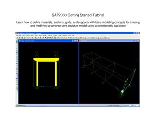
  • 1. SAP2000 Getting Started Tutorial Learn how to define materials, sections, grids, and supports with basic modeling concepts for creating and modifying a concrete bent structure model using a nonprismatic cap beam
  • 2. Click File>New menu or button/icon to bring up the initial SAP2000 screen where you select units and choose whether you want to work with grids or one of the templates. For this tutorial, we will work with Grids, but you will probably want to explore the Quick BrIM options for modeling of simple bridges later on. Choose Kip, ft, F units and click ‘Grid Only’ option
  • 3. This screen enables you to define equally spaced grids. Later you will learn how to modify and insert irregular spaced gridlines. Please type Number of Grid Lines and Grid Spacing as shown. Note how although we are in Kip-ft units, you can input with architectural units (180” below) at anytime and SAP2000 will automatically convert to current units after you tab.
  • 4. Below you will see the default split-screen view. Note that the planar view on the left (X-Y plan view) is highlighted in blue on the 3D model on the right. As an exercise, click the down arrow as shown below
  • 5. By pressing the down arrow, you move to the base, Z = 0, which is highlighted on the right window. Next, click xz button to switch to elevation view
  • 6. This changes the view from plan to X-Z elevation. Press the up arrow to move to X-Z elevation view Y=0 as shown
  • 7. Double click any gridline to display the Define grid system data dialogue. Here you can add, modify or delete gridlines at any time. Grids can be added out of numerical sequence and SAP2000 will automatically reorder them. Select rows and use Edit menu to delete. The ‘Glue to Grid Lines’ option, when activated, will move and stretch elements associated with a particular gridline that is modified. Cancel out of this dialogue to return to the main screen.
  • 8. Go to Define>Materials, press ‘Add New Material Quick’, Material type Concrete and add f’c 5000 psi concrete and press OK to add this new material. SAP2000 offers several libraries of materials for steel, concrete, aluminum and cold formed steel. To define a material not in our standard library, click ‘Add New Material’ button or ‘Add copy of material’ from an existing material and input material properties
  • 9. Next we will define frame sections. Go to Define>Section properties>Frame Sections. In this dialogue, you would click ‘Import New Property’ only if you want to import standard steel sections from a library (AISC and international libraries of sections). For nonstandard steel sections such as Plate Girders, nonprismatic sections, or concrete sections, you use the ‘Add New Property’. Click the ‘Add New property’ button
  • 10. Select Concrete from the pull down Frame section property type. Please note that any shape in the steel shape list can be changed to concrete, and conversely, any concrete shape can be modeled as steel. For example, you can define concrete I/Wide flanges using the steel shape options, or define solid circular steel rods using the concrete circular shape option.
  • 11. Click the Rectangular shape option, name the section 3x3 to remember it, change the Material to 5000 psi concrete which we defined earlier, and input 3ft in both the depth and width dimensions. Click ‘concrete reinforcement’ to modify or review design parameters. Then click ‘Set modifiers’ button. Here you can assign reduction factors to EI for analysis of cracked sections, or assign a multiplier to reduce or increase any section property in this dialogue. Press OK without changing any factors and press OK again to save this section You can type 3” and tab to change cover Commonly used to apply reduction factors to EI for cracked sections
  • 12. By clicking OK, the section is added to the working list on the left. Next, click ‘Add New Property’ button and click ‘Rectangular’ to add another section. Name it 3x1CapBM and type in Depth 3ft. And width of 1 foot. Press ‘concrete reinforcement’ button and change from Column to Beam as shown and press OK
  • 13. Click OK to accept this new section, click ‘Add New Property’ and ‘Rectangular’ once more to add another rectangular section. Name it 1.5x1CapBM, type in the dimensions shown below, click the Concrete reinforcement button and change to beam design type and press OK twice to add this section to the working list
  • 14. Next, to review SAP2000’s section designer, click ‘Add new property’ again with Frame section property type ‘Other’, click Section Designer, then in the SD Section data dialogue click the ‘Section Designer’ button
  • 15. Click one of the Caltrans section options and then click on the origin in the middle to draw it. Next, right click the section to review options and click OK without making any changes.
  • 16. Click options to display section properties, P-M-M curves, and moment curvature. The moment curvature plot also enables you to calculate cracked sections based on load if you select the ‘Caltrans idealized model’ option. Click Done and Ok until you exit the section designer as we wanted to introduce the SD capability within this tutorial, but we will not use a SD section for this exercise.
  • 17. Click ‘Add new property’ button once more, but this time click Concrete ‘Circular’ type, name it 15”CircularCOL, type 15” and then press tab to have SAP2000 convert to current ft. units. Click OK twice to accept and save defined sections. Click the save button and name the model Tutorial1
  • 18. You should still have a split screen view as shown below with X-Z planar view on the left. If not, click your left window to make it active, then click the xz button to change view and up/down arrow keys if you need to adjust further. Next, click ‘Draw frame/cable element’ button as shown and click the section to change the section property to 15”CircularCOL in the pop-up properties box.
  • 19. In X-Z view window, click once on the bottom left grid intersection and then click up to the top left grid intersection in order to draw the column. Next, right mouse click to lift your cursor to draw another column on the right side. Click once on the bottom right intersection and complete the column by clicking on the top right grid intersection. Next, press Esc key on your keyboard or the select button/icon to switch to select mode Draw column with two mouse clicks Elevation view
  • 20. Holding your left mouse key down, drag your mouse to window around the base of the two columns in order to select bottom joints as shown
  • 21. Next, use the Assign menu>Joint>Restraints to add fixed restraints as shown. Press OK
  • 22. Click ‘Draw frame/cable element’ button, change Section property to 3x1CapBM and click twice to draw the cap beam as shown. Click ‘Set Display options’ button and checkbox ‘Extrude view’ option and press OK
  • 23. The extruded view enables you to see a proportional rendered view of the model. You can see that we have basic centerline connection. By clicking in a window to make it ‘active’, you can display extruded view in 1 window or all windows. Click ‘Set display options’ box once more, uncheck the ‘extruded view’ option and select the beam by clicking on it as shown. Selected beam displays as dotted line
  • 24. Go to Assign>Frame loads>Point to assign point loads along the length of the beam. Using Relative percentage distance, change the 2nd distance to .2 and 3rd distance to .8 and input a 100 Kip load for 2 and 110 Kip load for 3 and press OK to assign these loads in the DEAD load pattern. By clicking the + button next to the load pattern name, you could define additional load pattern cases to assign the load to. Alternatively, you could Define load patterns and combos under the Define menu before assigning loads
  • 25. In order consider p-delta effects, go to Define>Load cases, click DEAD and press the ‘Add copy of load case’ button and checkbox Nonlinear and P-delta as shown below and press OK twice to accept. Alternatively, we could have modified the DEAD case, but by making a copy of it, we can compare results between the P-delta DEAD case and the DEAD case without P-delta in the same analysis
  • 26. Press F5 on your keyboard to run the analysis and press ‘Run now’ button as shown. After the analysis has completed, click the arrow next to the ‘Show forces/stresses’ button as shown and select Moment 3-3 to interactively display major moment.
  • 27. You can then right click individual frames for results as shown, toggling between cases and results options. Press Done.
  • 28. Use Display menu>Show tables to generate output tables and input summaries. You can select which load patterns and cases to include, which joints and elements you want to report and which reports you want to generate
  • 29. Using the table form, you can go to the File menu>Export current table and export to Excel or Access. You can utilize the Format-Filter-Sort menu option to format and to sort by min/max values in any specified direction.
  • 30. To perform an ACI 318-05 design check, go to Design menu>Concrete Frame design>View/Revise preferences to specify design parameters. Then go to Define menu>Load Combinations. Here you can define your own factored load combos, or let SAP2000 generate them automatically based on your selected design code.
  • 31. As an alternative to defining P-delta cases one-at-a-time as we did before, SAP2000 offers an option to automatically convert load combos into nonlinear P-delta cases by clicking the ‘Convert Combos to Nonlinear cases’ button on the load combo screen, then select/highlight the combos to be converted. To do a concrete design, first run an analysis. After the analysis completes, then run a concrete design by clicking the ‘Start concrete design/check’ button . After the design completes, you can right click individual frames for design results, or use the Design menu>Concrete frame design>Display design info, or use Display menu>Show tables to print and sort results Select load combos to convert into nonlinear P-delta cases
  • 32. Close the output forms, unlock the model, by clicking the unlock button ,say OK to the unlock warning. Next we’re going to define a nonprismatic cap beam, so go to Define>Section properties>Frame sections, click ‘Add new property’, ‘Other’ frame section property type and click ‘Nonprismatic’
  • 33. Accept the default VAR1 section name and type the values shown below for sections, lengths and length type. SAP2000 lets you define the length type by variable percentage or absolute length using current units (ft in this example). Press OK twice to return to the model
  • 34. Select the existing beam and press the Del (delete) key on your keyboard. Next, click the ‘Draw special joint’ button, type -3(feet) in the X direction and click the top of the left side column to draw a joint 3 feet away as shown. You may or may not have to add the Draw special joint button to your palette using the ‘More buttons’ arrow Draw special Joint button Add more buttons
  • 35. Next, change offset dimension to (+) 3 feet in the X direction and click the top of the right column to add another joint. Next, click ‘Draw frame/cable element’ button , change section to VAR1 with continuous connection and connect the dots by clicking once on the special joint on the left and then complete the beam by clicking on the special joint on the right as shown. SAP2000’s object based modeling will automatically connect the columns to the beam with no further meshing required. Special joints with snap tools can also be used to add joints on frames to assign joint loads without manually dividing the frame
  • 36. Press Esc key or click select arrow button to exit draw mode. Click the ‘Set display options’ menu and checkbox extrude view for the planar view. Hold down your left mouse key and drag right to left while intersecting the beam in order to select
  • 37. Next, use the main menu and go to Assign>Frame>Insertion point. Then press the F1 key on your keyboard to read more about this feature, which lets you assign cardinal point offsets + additional offsets. Please select cardinal point 8 (top center) with additional 3 ft. joint offsets in the local 2 direction as shown. Local 2 direction = Z in global coordinate system for this beam. Press OK
  • 38. To delete restraints, you need to select the joints where restraints are assigned by windowing around the base of the bent structure, then Assign>Joint>Restraints and click the black dot to assign a null which deletes the restraints. Next, go to Define menu>Section properties>Link/support properties where you can define other supports known as “links”, which can be 1 point or 2 point links. Click ‘Add new property’ button to review options. Below right is the multi-linear plastic spring which is commonly used for nonlinear pile/soil interaction to define P-Y and T-Z curves
  • 39. There are also nonlinear link property options for gap springs, base isolators (friction bearing and elastomer), nonlinear viscous damper with velocity exponent with linear options to assign dashpots C and linear springs K. Under define menu you will also see the option to define frequency dependent K and C for dynamic analysis, as geotechnical data may report soil properties as a function of frequency. Links can be assigned as point supports, or on a per lineal unit basis on frame elements, or per area basis for shells and solid finite elements. In this manner, you can easily model piles explicitly using circular or rectangular frame elements, then assign the link as a frame spring/link assignment.
  • 40. We’ll end the tutorial here by demonstrating two more options: Replicate commands, rotating frame local axis, and assignment of shear and moment releases. Check the bottom right portion of your screen to make sure you’re in Kip-ft units, click the ‘Select all’ button to select and then Edit>Replicate. Here you can copy and paste in linear, radial or mirror fashion. If you want to rotate all or a portion of the entire structure, you do it with Replicate, just checkbox the ‘Delete Original Object’ box
  • 41. To rotate local axis of frames or to assign moment and/or shear releases, first select frames by clicking them or using one of the Select menu options, then Assign>Frame>Local axes and type an angle in order to rotate local axes. If you want to assign releases, choose the Assign>Frame>Releases/Partial fixity option shown below on the right
  • 42. There are several good Watch & Learn video tutorials on our website here http://www.csiberkeley.com/Support_WL_SAP.html which cover bridge modeling and other features of SAP2000. These videos are good tools to help you get started while minimizing the learning curve. Also, the SAP2000 Help menu enables you to access user manuals and other documentation. Please feel free to contact me if you have feedback or suggestions regarding this tutorial or if you have SAP2000 modeling questions. I’m here to help new users get started: Darrell Foster CSI Houston, TX office Tel: 713-533-4420 Computers & Structures, Inc. TECHNOLOGY FOR A BETTER WORLD darrell@csiberkeley.com www.csiberkeley.com